EP1201969A1 - Fluid recovery system for an automatic transmission unit - Google Patents
Fluid recovery system for an automatic transmission unit Download PDFInfo
- Publication number
- EP1201969A1 EP1201969A1 EP01125915A EP01125915A EP1201969A1 EP 1201969 A1 EP1201969 A1 EP 1201969A1 EP 01125915 A EP01125915 A EP 01125915A EP 01125915 A EP01125915 A EP 01125915A EP 1201969 A1 EP1201969 A1 EP 1201969A1
- Authority
- EP
- European Patent Office
- Prior art keywords
- tank
- fluid
- transmission unit
- recovery system
- fluid recovery
- Prior art date
- Legal status (The legal status is an assumption and is not a legal conclusion. Google has not performed a legal analysis and makes no representation as to the accuracy of the status listed.)
- Granted
Links
- 239000012530 fluid Substances 0.000 title claims abstract description 84
- 238000011084 recovery Methods 0.000 title claims abstract description 38
- 230000005540 biological transmission Effects 0.000 title claims abstract description 29
- 230000000694 effects Effects 0.000 claims description 3
- 230000005484 gravity Effects 0.000 claims description 3
- 239000007789 gas Substances 0.000 description 20
- 238000010586 diagram Methods 0.000 description 4
- 238000004064 recycling Methods 0.000 description 3
- 238000002485 combustion reaction Methods 0.000 description 1
- 238000012423 maintenance Methods 0.000 description 1
- 230000007257 malfunction Effects 0.000 description 1
Images



Classifications
-
- F—MECHANICAL ENGINEERING; LIGHTING; HEATING; WEAPONS; BLASTING
- F16—ENGINEERING ELEMENTS AND UNITS; GENERAL MEASURES FOR PRODUCING AND MAINTAINING EFFECTIVE FUNCTIONING OF MACHINES OR INSTALLATIONS; THERMAL INSULATION IN GENERAL
- F16H—GEARING
- F16H57/00—General details of gearing
- F16H57/04—Features relating to lubrication or cooling or heating
-
- Y—GENERAL TAGGING OF NEW TECHNOLOGICAL DEVELOPMENTS; GENERAL TAGGING OF CROSS-SECTIONAL TECHNOLOGIES SPANNING OVER SEVERAL SECTIONS OF THE IPC; TECHNICAL SUBJECTS COVERED BY FORMER USPC CROSS-REFERENCE ART COLLECTIONS [XRACs] AND DIGESTS
- Y10—TECHNICAL SUBJECTS COVERED BY FORMER USPC
- Y10T—TECHNICAL SUBJECTS COVERED BY FORMER US CLASSIFICATION
- Y10T137/00—Fluid handling
- Y10T137/8593—Systems
- Y10T137/85978—With pump
- Y10T137/86035—Combined with fluid receiver
- Y10T137/86067—Fluid sump
Definitions
- the present invention relates to a fluid recovery system for an automatic transmission unit.
- the above-mentioned actuators are generally of hydraulic or electro-hydraulic type and are supplied by means of a hydraulic pump receiving an operating fluid (normally oil) from a hydraulic circuit which is coupled to the actuators and is adapted to provide these actuators with the pressurised operating fluid so that they can operate.
- an operating fluid normally oil
- This situation may cause fluid to escape from the hydraulic circuit causing a possible malfunction of the automatic transmission unit and pollution of the external environment; when the quantity of operating fluid escaping from the circuit as a result of leakages is a substantial proportion, for instance 20-30%, of the volume of the operating fluid in the hydraulic circuit, operating anomalies may occur as a result, for instance, of the intake of air or other gases by the pump.
- a known solution is to provide the hydraulic actuators with high quality gaskets so as to reduce fluid leakages to predetermined values.
- the object of the present invention is therefore to provide an operating fluid recovery system for a transmission unit which is free from the above-mentioned drawbacks.
- the present invention relates to an operating fluid recovery system for a transmission unit as described in claim 1.
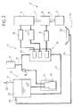
- the engine 3 supplies mechanical power via an output shaft 4 to the transmission unit 2 comprising a gear change 5 and a clutch 6 interposed between the output shaft 4 of the engine 3 and an input shaft 7 of the gear change 5.
- the clutch 6 is in particular associated with a first actuator unit 8 causing the clutch 6 to open and close, and the gear change 5 is associated with a second and a third actuator unit 9, 10 in order to control the selection and the engagement/disengagement of the gears of the gear change 5 respectively.
- the first, second and third actuator units 8, 9, 10 receive pressurised operating fluid (for instance oil) from a hydraulic circuit 11.
- pressurised operating fluid for instance oil
- the hydraulic circuit in particular comprises:
- the system 1 further comprises a collection zone 22, for instance a dedicated tank or a built-in tank adapted to collect the fluid escaping from the first and/or second and/or third actuator units 8, 9, 10, and a recovery duct 23 connecting the collection zone 22 to the upper end of the tank 13 so that the fluid in the collection zone 22 can be returned to the tank 13.
- the collection zone 22 may in particular be shaped as a tank disposed adjacent and below the first and/or second and/or third actuator unit 8, 9, 10, in order to collect operating fluid leaking from the actuators and reaching, under the effect of gravity, the collection zone 22.
- a plurality of collection zones may also be provided and associated respectively with the first, second and third actuator units 8, 9, 10 with outlets that flow into the duct 23.
- the collection zone 22 is preferably but not exclusively disposed at a height lower than the height at which the tank 13 is disposed.
- Fluid is returned by means of a reduction of the pressure of the gas in the tank 13 caused by the actuation of one of the actuator units 8, 9, 10.
- the first actuator unit 8 is actuated in a first direction, this actuation causing a reduction of the volume of the fluid in the tank 13 and therefore, since the tank 13 is closed, a reduction of the pressure of the gas in this tank 13.
- the fluid collected in the collection zone 22 is subject to a pressure difference which causes this fluid to pass through the recovery duct 23 from the collection zone 22 to the tank 13.
- the first actuator unit 8 is actuated in the direction opposite to the previous direction causing an increase in the volume of working fluid in the tank 13 and therefore an increase in the pressure of the gas in this tank 13. If the pressure of the gas in the tank is higher than or equal to the external ambient pressure, the operating fluid in the recovery duct 23 escapes from the latter to the collection zone 22.
- the quantity of fluid returned to the collection zone 22 via the recovery duct 23 can be made negligible.
- a second embodiment of a fluid recovery system for transmission units is shown overall by 30 and is similar to the system 1 described above. Components of this second embodiment corresponding to those of the system 1 will bear the same reference numerals in the following description.
- the system 30 in particular comprises a vent duct 31 connected at the upper end of the tank 13, and a first one-way valve 32 mounted on the vent duct 31 externally to the tank 13 in order to enable a one-way exchange of the gas in the tank 13 with the external atmosphere; the first valve 32 is in particular adapted to prevent the gas from flowing back into the tank 13 and to enable the gas to flow externally from the tank 13 when the external ambient pressure is lower than the pressure of the gas in the tank 13.
- the system 30 further comprises a second one-way valve 33 interposed between the recovery duct 23 and the tank 13 and adapted to prevent the operating fluid from flowing back from the recovery duct 23 to the collection zone 22 when the pressure of the gas in the tank 13 is greater than the external ambient pressure; the second valve 33 is also adapted to move into an open position to enable operating fluid to be returned to the tank 13 when the pressure to which the operating fluid in the collection zone 22 is subject is greater than the pressure of the gas in the tank 13.
- the first actuator unit 8 is actuated causing an increase in the volume of fluid in the tank 13 and therefore an increase in the pressure of the gas in this tank 13.
- the gas is caused to escape from the tank 13 via the first one-way valve 32.
- the second one-way valve 33 prevents any fluid in the recovery duct 23 from flowing into the collection zone 22.
- the first actuator unit 8 is actuated and moves in a direction opposite to the previous closing direction, causing a decrease in the volume of fluid in the tank 13. Since the first one-way valve 32 prevents air from flowing back from the external environment into the tank 13, a low pressure is created in the tank 13 which promotes the return of the operating fluid from the collection zone 22 to the interior of the tank 13.
- the low pressure of the gas in the tank is also generated when, as a result of a pressure drop in the hydraulic circuit, the pump 14 is actuated to supply the hydraulic collector 16.
- the pump 14 supplies the hydraulic collector 16 receiving the operating fluid from the tank 13 in which the volume of operating fluid is reduced, thereby generating a reduction of the gas pressure.
- a third embodiment of a fluid recovery system for transmission units is shown overall by 40 and is similar to the system 1 described above. Components of this third embodiment corresponding to those of the system 1 will bear the same reference numerals in the following description.
- the system 40 comprises a zone 41 in which a low pressure is generated (low pressure zone); this zone may be formed, for instance, by a plurality of intake ducts of the engine 3 or by a circuit of a low-pressure servo-brake of the vehicle (not shown).
- the system 40 further comprises a low pressure duct 42 which connects, via a first one-way valve 43, the low pressure zone 41 and the upper end of the tank 13, which is provided with a separator baffle 44 disposed at the location of the connection between the low pressure duct 42 and the tank 13 to prevent the fluid in the tank 13 from escaping from this tank 13 and reaching the low pressure zone 41 via the low pressure duct 42.
- the system 40 lastly comprises a second one-way valve 45 connected to an end of the recovery duct at the location of the tank 13 and adapted to prevent the fluid from escaping from the recovery duct 23 into the collection zone 22.
- the fluid is also returned from the collection zone 22 to the tank 13 by means of a low pressure generated by the low pressure zone 41 within the tank 13.
- the tank 13 is always kept at low pressure irrespective of the direction of operation of the actuator units 8, 9 and 10.
- a fourth embodiment of a fluid recovery system for transmission units is shown overall by 50 and is similar to the system 1 described above. Components of this fourth embodiment corresponding to those of the system 1 will bear the same reference numerals in the following description.
- the tank 13 is disposed at a height which is lower than that of the collection zone 22, such that the fluid is returned from the collection zone 22 to the tank 13 via the recovery duct 23 chiefly under the effect of gravity.
- the present system has the advantage that it is economic, simple to produce and ensures that the transmission unit operates even when there are leakages of fluid from the actuators as a result of damage to the gaskets.
- the above-described system therefore enables the use of low-cost gaskets without the need for frequent resealing operations.
Landscapes
- Engineering & Computer Science (AREA)
- General Engineering & Computer Science (AREA)
- Mechanical Engineering (AREA)
- Control Of Transmission Device (AREA)
- Hydraulic Clutches, Magnetic Clutches, Fluid Clutches, And Fluid Joints (AREA)
- General Details Of Gearings (AREA)
- Exposure Control For Cameras (AREA)
- Gear-Shifting Mechanisms (AREA)
Abstract
Description

Claims (11)
- A fluid recovery system (1, 30, 40, 50) for an automatic transmission unit (2) of a vehicle, which system (1, 30, 40, 50) comprises a tank (13) containing a fluid, a hydraulic circuit (11) receiving this fluid from the tank (13), an electrovalve unit (19) supplied by the hydraulic circuit (11) and adapted to control actuator units (8, 9, 10) in order to actuate the opening and closing of a clutch (6) and to perform the selection and engagement/disengagement of the gears of a gear change (5), the system (1, 30, 40, 50) being characterised in that it comprises at least one collection means (22) adapted to recover the fluid escaping from the actuator units (8, 9, 10) and at least one duct means (23) connecting the collection means (22) to the tank (13) so that the fluid recovered in the collection means (22) can be returned to the tank (13).
- A fluid recovery system (1, 30) for a transmission unit as claimed in claim 1, characterised in that the fluid is returned by means of a variation of the pressure of a gas contained in the tank (13).
- A fluid recovery system (1, 30) for a transmission unit as claimed in claim 2, characterised in that the variation of the gas pressure is generated following the operation of at least one of the actuator units (8, 9, 10).
- A fluid recovery system (1, 30) for a transmission unit as claimed in claim 2, characterised in that the variation of the gas pressure is generated following the variation of the volume of operating fluid in the collection means (22).
- A fluid recovery system (30) for a transmission unit as claimed in claim 3, characterised in that it comprises first one-way valve means (32) coupled (31) to the tank (13) and adapted to enable the output of gas from the tank (13) and to prevent gas from flowing back into the tank (13).
- A fluid recovery system (30) for a transmission unit as claimed in claim 3, 4 or 5, characterised in that it comprises second one-way valve means (33) coupled to the duct means (23) to enable fluid to flow to the tank (13) and to prevent fluid from flowing back from the tank (13) to the collection zone (22).
- A fluid recovery system (40) for a transmission unit as claimed in claim 1, characterised in that it comprises low pressure generator means (41) communicating (42) with the tank (13) and generating a low pressure in the tank (13) enabling the suction of the recovered fluid from the collection means (22).
- A fluid recovery system (40) for a transmission unit as claimed in claim 7, characterised in that the low pressure generator means (41) comprise at least one intake duct of the engine (3) of the vehicle.
- A fluid recovery system (40) for a transmission unit as claimed in claim 7, characterised in that the low pressure generator means (41) comprise a circuit of a servo-brake of the vehicle.
- A fluid recovery system (50) for a transmission unit as claimed in claim 1, characterised in that the collection means (22) are disposed above the tank (13) so that that the fluid can be returned to the tank (13) chiefly under the effect of the force of gravity.
- A fluid recovery system (1, 30, 40, 50) for a transmission unit (2) as claimed in any one of the preceding claims, characterised in that the collection zone (22) comprises a tank (22).
Applications Claiming Priority (2)
| Application Number | Priority Date | Filing Date | Title |
|---|---|---|---|
| IT2000TO001029A IT1320741B1 (en) | 2000-10-31 | 2000-10-31 | FLUID RECOVERY SYSTEM FOR AN AUTOMATED TRANSMISSION GROUP. |
| ITTO001029 | 2000-10-31 |
Publications (2)
| Publication Number | Publication Date |
|---|---|
| EP1201969A1 true EP1201969A1 (en) | 2002-05-02 |
| EP1201969B1 EP1201969B1 (en) | 2004-02-18 |
Family
ID=11458177
Family Applications (1)
| Application Number | Title | Priority Date | Filing Date |
|---|---|---|---|
| EP01125915A Expired - Lifetime EP1201969B1 (en) | 2000-10-31 | 2001-10-30 | Fluid recovery system for an automatic transmission unit |
Country Status (6)
| Country | Link |
|---|---|
| US (1) | US6739999B2 (en) |
| EP (1) | EP1201969B1 (en) |
| BR (1) | BR0105848B1 (en) |
| DE (1) | DE60102053T2 (en) |
| ES (1) | ES2214373T3 (en) |
| IT (1) | IT1320741B1 (en) |
Families Citing this family (3)
| Publication number | Priority date | Publication date | Assignee | Title |
|---|---|---|---|---|
| ITPD20060126A1 (en) * | 2006-04-05 | 2007-10-06 | Omvl Srl | CONTROL DEVICE FOR DELIVERING A COMBUSTIBLE GAS IN INTERNAL COMBUSTION ENGINES. |
| ATE462082T1 (en) * | 2007-06-04 | 2010-04-15 | Magneti Marelli Spa | ACTUATING SYSTEM FOR A SERVO-CONTROLLED MECHANICAL TRANSMISSION WITH OIL LEAK RECOVERY |
| US7740455B1 (en) * | 2007-07-09 | 2010-06-22 | Brian Nissen | Pumping system with hydraulic pump |
Citations (4)
| Publication number | Priority date | Publication date | Assignee | Title |
|---|---|---|---|---|
| JPS62209268A (en) * | 1986-03-11 | 1987-09-14 | Nissan Motor Co Ltd | Oil level controller for transmission |
| EP0644370A1 (en) * | 1993-09-21 | 1995-03-22 | Agco Corporation | Clutch assembly with automatic oil level control system |
| DE19856941C1 (en) * | 1998-12-10 | 2000-02-17 | Daimler Chrysler Ag | Lubrication system for gearbox in road vehicle incorporates pump and control valve |
| JP2000257705A (en) * | 1999-03-08 | 2000-09-19 | Hino Motors Ltd | Transmission lubrication system |
Family Cites Families (7)
| Publication number | Priority date | Publication date | Assignee | Title |
|---|---|---|---|---|
| US3003659A (en) * | 1958-09-11 | 1961-10-10 | Clark Equipment Co | Collapsible reservoir |
| GB1498011A (en) * | 1974-02-14 | 1978-01-18 | Srm Hydromekanik Ab | Transmission including a hydrodynamic torque converter |
| US4782851A (en) * | 1987-08-10 | 1988-11-08 | General Motors Corporation | Capillary valve for hydraulic systems |
| US5105922A (en) * | 1991-04-01 | 1992-04-21 | Dana Corporation | Hydraulic clutch and transmission actuating system |
| KR19980017013A (en) * | 1996-08-30 | 1998-06-05 | 박병재 | Hydraulic control system of automatic transmission for vehicles |
| US5901744A (en) * | 1996-09-06 | 1999-05-11 | Richards; Samuel K. | Water supply system for a water source with limited flow capability |
| JP3651655B2 (en) * | 1999-04-30 | 2005-05-25 | ジヤトコ株式会社 | Control device for automatic transmission |
-
2000
- 2000-10-31 IT IT2000TO001029A patent/IT1320741B1/en active
-
2001
- 2001-10-26 BR BRPI0105848-7A patent/BR0105848B1/en not_active IP Right Cessation
- 2001-10-30 US US09/984,635 patent/US6739999B2/en not_active Expired - Lifetime
- 2001-10-30 DE DE60102053T patent/DE60102053T2/en not_active Expired - Lifetime
- 2001-10-30 ES ES01125915T patent/ES2214373T3/en not_active Expired - Lifetime
- 2001-10-30 EP EP01125915A patent/EP1201969B1/en not_active Expired - Lifetime
Patent Citations (4)
| Publication number | Priority date | Publication date | Assignee | Title |
|---|---|---|---|---|
| JPS62209268A (en) * | 1986-03-11 | 1987-09-14 | Nissan Motor Co Ltd | Oil level controller for transmission |
| EP0644370A1 (en) * | 1993-09-21 | 1995-03-22 | Agco Corporation | Clutch assembly with automatic oil level control system |
| DE19856941C1 (en) * | 1998-12-10 | 2000-02-17 | Daimler Chrysler Ag | Lubrication system for gearbox in road vehicle incorporates pump and control valve |
| JP2000257705A (en) * | 1999-03-08 | 2000-09-19 | Hino Motors Ltd | Transmission lubrication system |
Non-Patent Citations (2)
| Title |
|---|
| PATENT ABSTRACTS OF JAPAN vol. 012, no. 064 (M - 672) 26 February 1988 (1988-02-26) * |
| PATENT ABSTRACTS OF JAPAN vol. 2000, no. 12 3 January 2001 (2001-01-03) * |
Also Published As
| Publication number | Publication date |
|---|---|
| US6739999B2 (en) | 2004-05-25 |
| DE60102053D1 (en) | 2004-03-25 |
| EP1201969B1 (en) | 2004-02-18 |
| ES2214373T3 (en) | 2004-09-16 |
| US20020079256A1 (en) | 2002-06-27 |
| IT1320741B1 (en) | 2003-12-10 |
| DE60102053T2 (en) | 2004-12-30 |
| BR0105848A (en) | 2002-06-25 |
| BR0105848B1 (en) | 2009-05-05 |
| ITTO20001029A0 (en) | 2000-10-31 |
| ITTO20001029A1 (en) | 2002-05-01 |
Similar Documents
| Publication | Publication Date | Title |
|---|---|---|
| US8771138B2 (en) | Hybrid hydraulic drive system architecture | |
| US7690450B2 (en) | System for operating a hydraulically actuated device | |
| US20100012052A1 (en) | Method for operating a hybrid drive | |
| KR101466607B1 (en) | Electro-hydraulic clutch system | |
| CN101255921A (en) | Hydraulic control device for automated double clutch transmission | |
| CN110864105B (en) | Hydraulic system for a dual clutch transmission | |
| KR20160014755A (en) | Method for controlling an accumulator based on vehicle conditions | |
| JP2008542663A (en) | Automatic countershaft transmission and manufacturing method thereof | |
| WO2017034828A1 (en) | Fluid conditioning system with recirculation loop and method for operating same | |
| EP1201969B1 (en) | Fluid recovery system for an automatic transmission unit | |
| CN103363104A (en) | System and method for accumulator fluid mixing | |
| CN203713568U (en) | Bilateral pneumatically-operated control system for power takeoff | |
| JP2006233919A (en) | Drive device for hybrid vehicle | |
| US6332855B1 (en) | Controller for an automatic transmission | |
| KR101755804B1 (en) | Recovered power transfer apparatus of waste heat recovery system | |
| US10473024B2 (en) | Turbocompound unit | |
| KR20000062991A (en) | Power take-off unit housing having integral hydraulic manifold | |
| CN211901378U (en) | An electronic pneumatic clutch actuator and electronic pneumatic clutch actuator system | |
| CN108980231B (en) | A kind of hybrid electric vehicle power control system and hybrid electric vehicle | |
| KR102084326B1 (en) | Variable oil pump with electric motor inside | |
| CN104455390A (en) | Hybrid electric vehicle and gearbox hydraulic control system thereof | |
| KR20220086091A (en) | Hydraulic control system of transmission for electric vehicle | |
| CN117489780B (en) | Gear shifting transmission device, gear shifting control method and hybrid power vehicle | |
| CN104494424A (en) | Driving device for shaft belt equipment, shaft belt equipment module and power system | |
| CN104696505A (en) | A method of ensuring oil supplying in an automatic transmission |
Legal Events
| Date | Code | Title | Description |
|---|---|---|---|
| PUAI | Public reference made under article 153(3) epc to a published international application that has entered the european phase |
Free format text: ORIGINAL CODE: 0009012 |
|
| AK | Designated contracting states |
Kind code of ref document: A1 Designated state(s): DE ES FR GB SE Kind code of ref document: A1 Designated state(s): AT BE CH CY DE DK ES FI FR GB GR IE IT LI LU MC NL PT SE TR |
|
| AX | Request for extension of the european patent |
Free format text: AL;LT;LV;MK;RO;SI |
|
| 17P | Request for examination filed |
Effective date: 20021029 |
|
| AKX | Designation fees paid |
Free format text: DE ES FR GB SE |
|
| GRAP | Despatch of communication of intention to grant a patent |
Free format text: ORIGINAL CODE: EPIDOSNIGR1 |
|
| GRAS | Grant fee paid |
Free format text: ORIGINAL CODE: EPIDOSNIGR3 |
|
| GRAA | (expected) grant |
Free format text: ORIGINAL CODE: 0009210 |
|
| AK | Designated contracting states |
Kind code of ref document: B1 Designated state(s): DE ES FR GB SE |
|
| REG | Reference to a national code |
Ref country code: GB Ref legal event code: FG4D |
|
| RAP2 | Party data changed (patent owner data changed or rights of a patent transferred) |
Owner name: MAGNETI MARELLI POWERTRAIN S.P.A. |
|
| REG | Reference to a national code |
Ref country code: IE Ref legal event code: FG4D |
|
| REF | Corresponds to: |
Ref document number: 60102053 Country of ref document: DE Date of ref document: 20040325 Kind code of ref document: P |
|
| REG | Reference to a national code |
Ref country code: SE Ref legal event code: TRGR |
|
| REG | Reference to a national code |
Ref country code: ES Ref legal event code: FG2A Ref document number: 2214373 Country of ref document: ES Kind code of ref document: T3 |
|
| ET | Fr: translation filed | ||
| PLBE | No opposition filed within time limit |
Free format text: ORIGINAL CODE: 0009261 |
|
| STAA | Information on the status of an ep patent application or granted ep patent |
Free format text: STATUS: NO OPPOSITION FILED WITHIN TIME LIMIT |
|
| 26N | No opposition filed |
Effective date: 20041119 |
|
| PGFP | Annual fee paid to national office [announced via postgrant information from national office to epo] |
Ref country code: GB Payment date: 20090928 Year of fee payment: 9 Ref country code: SE Payment date: 20090924 Year of fee payment: 9 |
|
| PGFP | Annual fee paid to national office [announced via postgrant information from national office to epo] |
Ref country code: ES Payment date: 20091006 Year of fee payment: 9 |
|
| GBPC | Gb: european patent ceased through non-payment of renewal fee |
Effective date: 20101030 |
|
| PG25 | Lapsed in a contracting state [announced via postgrant information from national office to epo] |
Ref country code: GB Free format text: LAPSE BECAUSE OF NON-PAYMENT OF DUE FEES Effective date: 20101030 |
|
| PG25 | Lapsed in a contracting state [announced via postgrant information from national office to epo] |
Ref country code: SE Free format text: LAPSE BECAUSE OF NON-PAYMENT OF DUE FEES Effective date: 20101031 |
|
| REG | Reference to a national code |
Ref country code: ES Ref legal event code: FD2A Effective date: 20111118 |
|
| PG25 | Lapsed in a contracting state [announced via postgrant information from national office to epo] |
Ref country code: ES Free format text: LAPSE BECAUSE OF NON-PAYMENT OF DUE FEES Effective date: 20101031 |
|
| REG | Reference to a national code |
Ref country code: FR Ref legal event code: PLFP Year of fee payment: 15 |
|
| REG | Reference to a national code |
Ref country code: FR Ref legal event code: PLFP Year of fee payment: 16 |
|
| REG | Reference to a national code |
Ref country code: FR Ref legal event code: PLFP Year of fee payment: 17 |
|
| REG | Reference to a national code |
Ref country code: FR Ref legal event code: PLFP Year of fee payment: 18 |
|
| PGFP | Annual fee paid to national office [announced via postgrant information from national office to epo] |
Ref country code: FR Payment date: 20200917 Year of fee payment: 20 |
|
| PGFP | Annual fee paid to national office [announced via postgrant information from national office to epo] |
Ref country code: DE Payment date: 20200917 Year of fee payment: 20 |
|
| REG | Reference to a national code |
Ref country code: DE Ref legal event code: R071 Ref document number: 60102053 Country of ref document: DE |