EP1201953A2 - Fluid clutch - Google Patents
Fluid clutch Download PDFInfo
- Publication number
- EP1201953A2 EP1201953A2 EP01123381A EP01123381A EP1201953A2 EP 1201953 A2 EP1201953 A2 EP 1201953A2 EP 01123381 A EP01123381 A EP 01123381A EP 01123381 A EP01123381 A EP 01123381A EP 1201953 A2 EP1201953 A2 EP 1201953A2
- Authority
- EP
- European Patent Office
- Prior art keywords
- passage
- shaft
- pump
- casing
- gear
- Prior art date
- Legal status (The legal status is an assumption and is not a legal conclusion. Google has not performed a legal analysis and makes no representation as to the accuracy of the status listed.)
- Withdrawn
Links
- 239000012530 fluid Substances 0.000 title claims abstract description 49
- 230000005540 biological transmission Effects 0.000 description 9
- 230000008878 coupling Effects 0.000 description 9
- 238000010168 coupling process Methods 0.000 description 9
- 238000005859 coupling reaction Methods 0.000 description 9
- 230000002093 peripheral effect Effects 0.000 description 5
- 230000004308 accommodation Effects 0.000 description 4
- 238000002485 combustion reaction Methods 0.000 description 2
- 230000007423 decrease Effects 0.000 description 2
- 230000002159 abnormal effect Effects 0.000 description 1
- 230000001627 detrimental effect Effects 0.000 description 1
- 239000003814 drug Substances 0.000 description 1
- 229940079593 drug Drugs 0.000 description 1
- 230000000694 effects Effects 0.000 description 1
- 239000000446 fuel Substances 0.000 description 1
Images

Classifications
-
- F—MECHANICAL ENGINEERING; LIGHTING; HEATING; WEAPONS; BLASTING
- F16—ENGINEERING ELEMENTS AND UNITS; GENERAL MEASURES FOR PRODUCING AND MAINTAINING EFFECTIVE FUNCTIONING OF MACHINES OR INSTALLATIONS; THERMAL INSULATION IN GENERAL
- F16D—COUPLINGS FOR TRANSMITTING ROTATION; CLUTCHES; BRAKES
- F16D31/00—Fluid couplings or clutches with pumping sets of the volumetric type, i.e. in the case of liquid passing a predetermined volume per revolution
- F16D31/04—Fluid couplings or clutches with pumping sets of the volumetric type, i.e. in the case of liquid passing a predetermined volume per revolution using gear-pumps
Definitions
- the present invention relates to a fluid clutch for transmitting a rotational torque of an internal combustion engine.
- a friction clutch, a fluid coupling and a torque converter have generally been used as clutches for transmitting the rotational torque of the internal combustion engines.
- the friction clutch comprises a flywheel mounted on a crank shaft of an engine, a pressure plate having a clutch facing disposed being opposed to the flywheel, and a clutch driven plate that is disposed between the flywheel and the pressure plate and is mounted on an input shaft of a transmission arranged on the same axis as the crank shaft.
- the transmission of torque is controlled by adjusting the pushing force exerted by the pressure plate.
- the fluid coupling and torque converter comprise a casing coupled to a crank shaft (input shaft) of an engine, a pump that is disposed being opposed to the casing and is mounted on the casing, a turbine that is disposed in a chamber formed by the pump and the casing so as to be opposed to the pump and is mounted on the output shaft arranged on the same axis as the crank shaft (input shaft), and an operation fluid filled in a pump chamber.
- a centrifugal force acts on the operation fluid in the pump due to the rotation of the pump, and the operation fluid that flows to the outer peripheral side due to the centrifugal force is permitted to flow into the turbine from the outer peripheral side thereof thereby to drive the turbine.
- the friction clutch has a clutch facing that is subject to be worn out. After used for a predetermined period of time, therefore, the friction clutch must be renewed. Besides, it is difficult to control the torque in the case of automatically controlling the clutch.
- the pump on the drive side and the turbine on the driven side are not in mechanical contact with each other and hence, are not subject to be worn out.
- the torque is not transmitted unless there is a difference in the rotational speed between the pump and the turbine, the transmission of torque becomes zero (0) when the ratio of the rotational speed of the pump to the turbine is nearly 1.
- a drag torque is produced due to its nature in a state where the vehicle is at rest, the engine is running and a speed change gear of the transmission is in mesh, i.e., in a state where the input shaft is revolving but the output shaft is at rest.
- the drag torque in general, stands for a torque that is transmitted in a state where the engine is in operation at an idling speed.
- the drag torque increases to a considerable degree when a design point of the fluid coupling and torque converter is set to be a rotational speed ratio at which a maximum efficiency is obtained, i.e., is set to be a rotational speed ratio of the pump to the turbine of from about 0.95 to about 0.98.
- a fluid clutch disposed between a first shaft and a second shaft which are arranged on the same axis, comprising:
- said intake passage and said exhaust passage are communicated with a supplementary passage, and check valves are disposed between said supplementary passage and said intake passage and between said supplementary passage and said exhaust passage, to permit the flow of the fluid from said supplementary passage to said intake passage and to said exhaust passage.
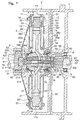
- Fig. 1 is a sectional view of the fluid clutch constituted according to the present invention
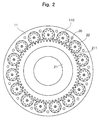
- Fig. 2 is a sectional view along the line A-A in Fig. 1.
- the fluid clutch in the illustrated embodiment has a clutch housing 2.
- a first shaft 3 e.g., crank shaft of an engine
- a second shaft 4 e.g., input shaft of a transmission
- the second shaft 4 is rotatably supported by a transmission casing 7 coupled to the clutch housing 2 through a bearing 8.
- a coupling plate 5 is coupled at its inner peripheral portion to the first shaft 3 by using bolts 6, and a casing 10 of the fluid clutch is drive-coupled to the outer peripheral portion of the coupling plate 5.
- the casing 10 comprises a first casing member 11 formed like a cup, a second casing member 12 which is disposed being opposed to the first casing member 11 and forms an accommodation chamber 100 together with the first casing member 11, for accommodating a first pump gear 21 that will be described later, a third casing member 13 disposed on the outer side of the first casing member 11 (on the left side in Fig. 1), and a fourth casing member 14 disposed on the outer side of the second casing member 12 (on the right side in Fig. 1). These members are coupled together with the coupling plate 5 by using bolts 15 and nuts 16.
- a support portion 111 protruding outward (toward the left in Fig.
- the first pump gear 21 is disposed in the accommodation chamber 100 formed in the casing 10.
- the first pump gear 21 has a gear 211 formed along the outer periphery thereof, and has an internal gear spline 213 formed in the inner periphery of the boss portion 212 thereof, the internal gear spline 213 being in spline-mesh with the external gear spline 41 formed on the fourth shaft 4.
- Second pump gears 22 are disposed in the plural pump chambers 110 and are in mesh with the gear 211 of the first pump gear 21.
- Rotary shafts 221 of the second pump gears 22 are rotatably supported by the first casing member 11 and by the second casing member 12.
- plural gear pumps 20 are constituted by the first pump gear 21 and the plural second pump gears 22 which are in mesh with each other.
- the first casing member 11 has exhaust ports 23 for the plural gear pumps 20 constituted by the first pump gear 21 and the plural second pump gears 22 when the casing 10 is driven from the side of the first shaft 3.
- the exhaust ports 23 of the gear pumps 20 are communicated with one another through communication passages that are not shown.
- the second casing member 12 has intake ports 24 for the plural gear pumps 20 constituted by the first pump gear 21 and the plural second pump gears 22 when the casing 10 is driven from the side of the first shaft 3.
- the intake ports 24, too, of the gear pumps 20 are communicated with one another through communication passages that are not shown. Described below are the exhaust ports 23 and the intake ports 24 of the gear pumps 20 in a state where the casing 10 is driven from the side of the first shaft 3.
- Each intake port 24 is communicated with the intake passage 255 formed in the second shaft 4 via an intake passage 251 formed by the second casing member 12 and the fourth casing member 14, an intake passage 252 formed in the second casing member 12, an intake passage 253 formed between the second casing member 12 and the first pump gear 21, and an intake passage 254 formed in the boss portion 212 of the first pump gear 21.
- each exhaust port 23 is communicated with an exhaust passage 265 formed in the second shaft 2 via an exhaust passage 261 formed by the first casing member 11 and the third casing member 13, an exhaust passage 262 formed in the first casing member 11, an exhaust passage 263 formed between the first casing member 11 and the first pump gear 21, and an exhaust passage 264 formed in the boss portion 212 of the first pump gear 21.
- the second shaft 4 has a valve hole 42 formed in the axial central portion thereof so as to be communicated with the intake passage 255 and with the exhaust passage 265.
- a control valve 30 is disposed in the valve hole 42 so as to slide in the axial direction.
- the control valve 30 comprises a first land portion 301 and a second land portion 302 both having an outer diameter corresponding to the diameter of the valve hole 42, and a shaft portion 303 having a small diameter is formed between the first land portion 301 and the second land portion 302.
- the outer peripheral side of the shaft portion 303 formed in a small diameter works as a communication passage for communicating the intake passage 255 with the exhaust passage 265.
- the control valve 30 has a through hole 304 formed in the central portion thereof.
- a plug 31 having a through hole 311 is fitted to the valve hole 42 at the left end in Fig. 1, and a coil spring 32 is disposed in a chamber 421 formed between the plug 31 and the control valve 30 to urge the control valve 30 toward the right in Fig. 1 at all times.
- a chamber 422 on the right side of the second land portion 302 constituting the control valve 30 in Fig. 1 is communicated with a control pressure passage 50 formed in the clutch housing 2 via a communication passage 45 formed in the second shaft 4.
- the control pressure passage 50 is communicated with a fluid pressure adjusting valve that is not shown.
- the controlled fluid of which the pressure is adjusted by a fluid pressure adjusting valve (not shown) is supplied to the chamber 422 through the control pressure passage 50 and the communication passage 45, and a controlled fluid pressure acts on the second land portion 302 constituting the control valve 30, so that the control valve 30 slides toward the left in Fig. 1 overcoming the resilient force of the coil spring 32.
- the control valve 30 is located between a first position where the first land portion 301 completely closes the exhaust passage 265 formed in the second shaft 4 as shown in Fig. 1 in compliance with the pressure of the controlled fluid and a second position where the exhaust passage 265 is completely opened as shown in Fig. 3, thereby to control the opening area of the exhaust passage 265.
- the control valve 30 has a function of controlling the communication area between the intake passage 255 and the exhaust passage 265.
- the fluid clutch has a supplementary passage 51 formed in the clutch housing 2.
- the supplementary passage 51 is connected, at its one end, to a reservoir tank that is not shown, and is coupled, at its other end, to a chamber 52 formed between the clutch housing 2 and the second casing member 12.
- the chamber 52 is communicated, through a communication passage 53 formed in the second casing member 12, with the intake passage 253 formed between the second casing member 12 and the first pump gear 21.
- the chamber 52 is further communicated, through a communication passage 54 formed in the clutch housing 2, with a chamber 55 formed between the clutch housing 2 and the second shaft 4.
- the chamber 55 is communicated, through a communication passage 56 formed in the second shaft 4, with a chamber 57 that is formed in the second shaft 4 and accommodates the right end of the control valve 30 in Fig. 1.
- a through hole 311 formed in the plug 31 fitted to the valve hole 42 at the left end in Fig. 1 is communicated with a chamber 61 formed between the second shaft 4 and the casing member 11.
- the chamber 61 is communicated with a chamber 63 formed between the first casing member 11 and the boss portion 212 of the first pump gear 21 through a gap 62 between the outer periphery of the plug 31 and the first casing member 11.
- the chamber 63 is communicated with the exhaust passage 263 formed between the first casing member 11 and the first pump gear 21 through a communication passage 64 formed in the bearing 17 and the first casing member 11.
- the supplementary passage 51 is communicated with the intake passage 253 formed between the second casing member 12 and the first pump gear 21 through the chamber 52 and communication passage 53, and is further communicated with the exhaust passage 263 formed between the first casing member 11 and the first pump gear 21 through the chamber 52, communication passage 54, chamber 55, communication passage 56, chamber 57, through hole 304 formed in the control valve 30, chamber 421, through hole 311 formed in the plug 31, chamber 61, gap 62 between the outer periphery of the plug 31 and the first casing member 11, chamber 63, bearing 17 and communication passage 64. Therefore, the above communication passages and the chambers work as supplementary passages communicated with the intake passage 253 and with the exhaust passage 263.
- a first ring-like check valve 71 is disposed between the communication passage 64 and the exhaust passage 263 that is formed between the first casing member 11 and the first pump gear 21.
- the first check valve 71 is closed when the fluid pressure in the exhaust passage 263 is higher than the fluid pressure in the communication passage 64, i.e., in the supplementary passage, and is opened when the fluid pressure in the exhaust passage 263 becomes lower than the fluid pressure in the communication passage 64, i.e., in the supplementary passage. Accordingly, the first check valve 71 works to permit the flow of the operation fluid from the supplementary passage to the exhaust passage.
- a second ring-like check valve 72 is disposed between the communication passage 53 and the intake passage 253 that is formed between the second casing member 12 and the first pump gear 21.
- the second check valve 72 is closed when the fluid pressure in the intake passage 253 is higher than the fluid pressure in the communication passage 53, i.e., in the supplementary passage, and is opened when the fluid pressure in the intake passage 253 becomes lower than the fluid pressure in the communication passage 53, i.e., in the supplementary passage. Therefore, the second check valve 72 works to permit the flow of the operation fluid from the supplementary passage to the intake passage.
- reference numeral 81 denotes a seal disposed between the first casing member 11 and the clutch housing 2
- reference numeral 82 denotes a seal disposed between the second shaft 4 and the clutch housing 2
- reference numeral 83 denotes a seal disposed between the second shaft 4 and the transmission casing 7.
- the fluid clutch according to the illustrated embodiment is constituted as described above. Now, described below is its operation.
- the control valve 30 is brought to the second position where the exhaust passage 265 is completely opened as shown in Fig. 3, the exhaust passage 265 is completely communicated with the intake passage 255 and, hence, the pressure does not much increase on the side of the exhaust port 23, the gear pumps 20 bear a small load, and the torque that is transmitted becomes the minimum.
- the position of the control valve 30 in the axial direction is controlled thereby to control the opening area of the exhaust passage 265 in order to arbitrarily control the torque that is transmitted from a maximum as shown in Fig. 1 to a minimum as shown in Fig. 3.
- the control valve 30 is disposed in the axial central portion of the second shaft 4. It is, therefore, allowed to increase the flow rate of the fluid that flows through the control valve 30 and, hence, to increase the range of torque that is transmitted.
- the fluid clutch of the present invention exhibits action and effect as described below.
- the fluid clutch according to the present invention controls the communication area between the intake passage of the gear pump and the exhaust passage by a control valve to easily control the torque that is transmitted.
- the fluid clutch of the invention has no friction member and hence, the clutch part is not worn out.
Landscapes
- Engineering & Computer Science (AREA)
- General Engineering & Computer Science (AREA)
- Mechanical Engineering (AREA)
- Details And Applications Of Rotary Liquid Pumps (AREA)
- Hydraulic Clutches, Magnetic Clutches, Fluid Clutches, And Fluid Joints (AREA)
- Rotary Pumps (AREA)
Abstract
Description
Claims (2)
- A fluid clutch disposed between a first shaft (3) and a second shaft (4) which are arranged on the same axis, comprising:a casing (10) drive-coupled to said first shaft (3) and having plural pump chambers (110);a gear pump (20) having a first pump gear (21) which is disposed in said casing (10), drive-coupled to said second shaft (4) and has a gear formed on the outer periphery thereof, and second plural pump gears (22) which are disposed in said plural pump chambers (110) formed in said casing (10) and are in mesh with said first pump gear (21);an intake passage (255) that is formed in said casing (10) and in said second shaft (4) and is communicated with an intake port (24) of said gear pump (20);an exhaust passage (265) that is formed in said casing (10) and in said second shaft (4) and is communicated with an exhaust port (23) of said gear pump (20); anda control valve (30) that is disposed in a valve hole (42) formed in said second shaft (4) and communicated with said intake passage (255) and with said exhaust passage (265), and that controls the communication area between said intake passage (255) and said exhaust passage (265).
- A fluid clutch according to claim 1, wherein said intake passage (255) and said exhaust passage (265) are communicated with a supplementary passage (51), and check valves (71, 72) are disposed between said supplementary passage (51) and said intake passage (255) and between said supplementary passage (51) and said exhaust passage (265), to permit the flow of the fluid from said supplementary passage (51) to said intake passage (255) and to said exhaust passage (265).
Applications Claiming Priority (2)
| Application Number | Priority Date | Filing Date | Title |
|---|---|---|---|
| JP2000330208 | 2000-10-30 | ||
| JP2000330208A JP2002130332A (en) | 2000-10-30 | 2000-10-30 | Fluid clutch |
Publications (2)
| Publication Number | Publication Date |
|---|---|
| EP1201953A2 true EP1201953A2 (en) | 2002-05-02 |
| EP1201953A3 EP1201953A3 (en) | 2003-06-25 |
Family
ID=18806768
Family Applications (1)
| Application Number | Title | Priority Date | Filing Date |
|---|---|---|---|
| EP01123381A Withdrawn EP1201953A3 (en) | 2000-10-30 | 2001-10-11 | Fluid clutch |
Country Status (3)
| Country | Link |
|---|---|
| US (1) | US6581742B2 (en) |
| EP (1) | EP1201953A3 (en) |
| JP (1) | JP2002130332A (en) |
Cited By (3)
| Publication number | Priority date | Publication date | Assignee | Title |
|---|---|---|---|---|
| EP1319855A1 (en) * | 2001-12-12 | 2003-06-18 | Isuzu Motors Limited | Fluid clutch |
| EP1724485A3 (en) * | 2005-05-19 | 2009-05-06 | Enver Hasic | Coupling |
| FR2975155A1 (en) * | 2011-05-12 | 2012-11-16 | Maurice Robert Vincelot | Automatic stepped transmission device for use in car to constantly monitor speed of rotation of e.g. thermal motor and receiver with variable gear ratios, has body that is used as transmission element in fluid circulation blocking |
Families Citing this family (1)
| Publication number | Priority date | Publication date | Assignee | Title |
|---|---|---|---|---|
| EP2679849B1 (en) * | 2012-06-26 | 2016-09-07 | BorgWarner Inc. | Fluid friction coupling |
Family Cites Families (9)
| Publication number | Priority date | Publication date | Assignee | Title |
|---|---|---|---|---|
| US2371227A (en) * | 1945-03-13 | Fluid clutch | ||
| US2066450A (en) * | 1936-01-21 | 1937-01-05 | Bascle Joseph Albon | Hydraulic clutch |
| DE854446C (en) * | 1944-10-11 | 1952-11-04 | Boehringer Gmbh Geb | Hydrostatic coupling with several pump gears arranged around a central wheel |
| GB1195021A (en) * | 1966-06-28 | 1970-06-17 | S R M Hydromekanic Ab | Improvements in and relating to Control Systems for Hydrostatic Coupling. |
| US4078453A (en) * | 1976-08-06 | 1978-03-14 | Russell Lyle Brace | Hydraulic power transmission |
| FR2456257A1 (en) * | 1979-05-09 | 1980-12-05 | Gant Martin | Fluid-operated clutch mechanism - has chambers alongside driving members producing pumping effect |
| US4674615A (en) * | 1985-10-23 | 1987-06-23 | Snyder Wayne E | Hydraulic clutch #III |
| JPS63140146A (en) * | 1986-11-28 | 1988-06-11 | Endo Haguruma Seisakusho:Kk | Speed change gear by fluid clutch |
| US4981201A (en) * | 1988-08-12 | 1991-01-01 | Paul D. Asmus | Variable drive apparatus |
-
2000
- 2000-10-30 JP JP2000330208A patent/JP2002130332A/en not_active Withdrawn
-
2001
- 2001-10-10 US US09/972,906 patent/US6581742B2/en not_active Expired - Fee Related
- 2001-10-11 EP EP01123381A patent/EP1201953A3/en not_active Withdrawn
Cited By (3)
| Publication number | Priority date | Publication date | Assignee | Title |
|---|---|---|---|---|
| EP1319855A1 (en) * | 2001-12-12 | 2003-06-18 | Isuzu Motors Limited | Fluid clutch |
| EP1724485A3 (en) * | 2005-05-19 | 2009-05-06 | Enver Hasic | Coupling |
| FR2975155A1 (en) * | 2011-05-12 | 2012-11-16 | Maurice Robert Vincelot | Automatic stepped transmission device for use in car to constantly monitor speed of rotation of e.g. thermal motor and receiver with variable gear ratios, has body that is used as transmission element in fluid circulation blocking |
Also Published As
| Publication number | Publication date |
|---|---|
| JP2002130332A (en) | 2002-05-09 |
| EP1201953A3 (en) | 2003-06-25 |
| US6581742B2 (en) | 2003-06-24 |
| US20020050435A1 (en) | 2002-05-02 |
Similar Documents
| Publication | Publication Date | Title |
|---|---|---|
| US4858572A (en) | Device for adjusting an angular phase difference between two elements | |
| US8342815B2 (en) | Oil pump | |
| US9017205B2 (en) | Transmission unit | |
| JP6706690B2 (en) | Oil pump and oil pump integrated balancer device | |
| JPH1137176A (en) | Clutch operating piston structure | |
| JPH08144965A (en) | Pump delivery control device for automatic transmission | |
| US4785923A (en) | Slippage control system for lock up clutch assembly for fluid coupling, providing non-electronic mechanical/hydraulic slippage control | |
| US4413960A (en) | Positionable control device for a variable delivery pump | |
| US7017340B2 (en) | Hydrokinetic torque converter for an automatic vehicle transmission | |
| KR100909311B1 (en) | Clutch assembly with gear pump | |
| EP0875678B1 (en) | Oil pump control valve | |
| US6581742B2 (en) | Fluid clutch | |
| US4696148A (en) | Hydraulic power transmission system | |
| US10975943B2 (en) | Torque converter assembly and method of operating the same | |
| JP2010529374A (en) | Torque transmission device | |
| KR100764490B1 (en) | Vacuum system comprising a vacuum pump and the vacuum pump | |
| US20030106760A1 (en) | Fluid clutch | |
| JP4573561B2 (en) | Positive displacement rotary pump | |
| JP2836427B2 (en) | Variable valve timing device | |
| CA2250476A1 (en) | Hydrostatic coupling comprising a planetary gear pump | |
| JPH02203078A (en) | Variable displacement type torque converter | |
| JP2002021742A (en) | Pump unit for vane pump | |
| JPH06185316A (en) | Variable valve timing controller | |
| KR100753897B1 (en) | Fluid pump with improved energy efficiency | |
| JP2020172914A (en) | Pump device |
Legal Events
| Date | Code | Title | Description |
|---|---|---|---|
| PUAI | Public reference made under article 153(3) epc to a published international application that has entered the european phase |
Free format text: ORIGINAL CODE: 0009012 |
|
| AK | Designated contracting states |
Kind code of ref document: A2 Designated state(s): AT BE CH CY DE DK ES FI FR GB GR IE IT LI LU MC NL PT SE TR |
|
| AX | Request for extension of the european patent |
Free format text: AL;LT;LV;MK;RO;SI |
|
| PUAL | Search report despatched |
Free format text: ORIGINAL CODE: 0009013 |
|
| AK | Designated contracting states |
Designated state(s): AT BE CH CY DE DK ES FI FR GB GR IE IT LI LU MC NL PT SE TR |
|
| AX | Request for extension of the european patent |
Extension state: AL LT LV MK RO SI |
|
| 17P | Request for examination filed |
Effective date: 20031121 |
|
| 17Q | First examination report despatched |
Effective date: 20040105 |
|
| AKX | Designation fees paid |
Designated state(s): DE FR GB |
|
| STAA | Information on the status of an ep patent application or granted ep patent |
Free format text: STATUS: THE APPLICATION IS DEEMED TO BE WITHDRAWN |
|
| 18D | Application deemed to be withdrawn |
Effective date: 20040518 |