EP1201909A2 - Double walled fuel rail - Google Patents
Double walled fuel rail Download PDFInfo
- Publication number
- EP1201909A2 EP1201909A2 EP01203960A EP01203960A EP1201909A2 EP 1201909 A2 EP1201909 A2 EP 1201909A2 EP 01203960 A EP01203960 A EP 01203960A EP 01203960 A EP01203960 A EP 01203960A EP 1201909 A2 EP1201909 A2 EP 1201909A2
- Authority
- EP
- European Patent Office
- Prior art keywords
- fuel
- conduit
- gas
- gas conduit
- delivery system
- Prior art date
- Legal status (The legal status is an assumption and is not a legal conclusion. Google has not performed a legal analysis and makes no representation as to the accuracy of the status listed.)
- Granted
Links
Images


Classifications
-
- F—MECHANICAL ENGINEERING; LIGHTING; HEATING; WEAPONS; BLASTING
- F02—COMBUSTION ENGINES; HOT-GAS OR COMBUSTION-PRODUCT ENGINE PLANTS
- F02M—SUPPLYING COMBUSTION ENGINES IN GENERAL WITH COMBUSTIBLE MIXTURES OR CONSTITUENTS THEREOF
- F02M37/00—Apparatus or systems for feeding liquid fuel from storage containers to carburettors or fuel-injection apparatus; Arrangements for purifying liquid fuel specially adapted for, or arranged on, internal-combustion engines
- F02M37/0011—Constructional details; Manufacturing or assembly of elements of fuel systems; Materials therefor
- F02M37/0017—Constructional details; Manufacturing or assembly of elements of fuel systems; Materials therefor related to fuel pipes or their connections, e.g. joints or sealings
-
- F—MECHANICAL ENGINEERING; LIGHTING; HEATING; WEAPONS; BLASTING
- F02—COMBUSTION ENGINES; HOT-GAS OR COMBUSTION-PRODUCT ENGINE PLANTS
- F02M—SUPPLYING COMBUSTION ENGINES IN GENERAL WITH COMBUSTIBLE MIXTURES OR CONSTITUENTS THEREOF
- F02M21/00—Apparatus for supplying engines with non-liquid fuels, e.g. gaseous fuels stored in liquid form
-
- F—MECHANICAL ENGINEERING; LIGHTING; HEATING; WEAPONS; BLASTING
- F02—COMBUSTION ENGINES; HOT-GAS OR COMBUSTION-PRODUCT ENGINE PLANTS
- F02M—SUPPLYING COMBUSTION ENGINES IN GENERAL WITH COMBUSTIBLE MIXTURES OR CONSTITUENTS THEREOF
- F02M25/00—Engine-pertinent apparatus for adding non-fuel substances or small quantities of secondary fuel to combustion-air, main fuel or fuel-air mixture
- F02M25/08—Engine-pertinent apparatus for adding non-fuel substances or small quantities of secondary fuel to combustion-air, main fuel or fuel-air mixture adding fuel vapours drawn from engine fuel reservoir
- F02M25/0872—Details of the fuel vapour pipes or conduits
-
- F—MECHANICAL ENGINEERING; LIGHTING; HEATING; WEAPONS; BLASTING
- F02—COMBUSTION ENGINES; HOT-GAS OR COMBUSTION-PRODUCT ENGINE PLANTS
- F02M—SUPPLYING COMBUSTION ENGINES IN GENERAL WITH COMBUSTIBLE MIXTURES OR CONSTITUENTS THEREOF
- F02M69/00—Low-pressure fuel-injection apparatus ; Apparatus with both continuous and intermittent injection; Apparatus injecting different types of fuel
- F02M69/46—Details, component parts or accessories not provided for in, or of interest apart from, the apparatus covered by groups F02M69/02 - F02M69/44
- F02M69/462—Arrangement of fuel conduits, e.g. with valves for maintaining pressure in the pipes after the engine being shut-down
- F02M69/465—Arrangement of fuel conduits, e.g. with valves for maintaining pressure in the pipes after the engine being shut-down of fuel rails
-
- F—MECHANICAL ENGINEERING; LIGHTING; HEATING; WEAPONS; BLASTING
- F02—COMBUSTION ENGINES; HOT-GAS OR COMBUSTION-PRODUCT ENGINE PLANTS
- F02M—SUPPLYING COMBUSTION ENGINES IN GENERAL WITH COMBUSTIBLE MIXTURES OR CONSTITUENTS THEREOF
- F02M55/00—Fuel-injection apparatus characterised by their fuel conduits or their venting means; Arrangements of conduits between fuel tank and pump F02M37/00
- F02M55/007—Venting means
Definitions
- This invention relates to a method and system for fuel delivery that limits the emission of fuel fumes into the environment.
- the invention comprises a fuel delivery system.
- the system has a fuel rail or conduit that has a wall formed of plastic.
- a gas rail or conduit surrounds this wall such that any gas vapor permeating through the fuel conduit passes into the gas conduit.
- the fuel conduit transports fuel to a vehicle's combustion chamber without significant environmental emissions.
- the gas conduit surrounds the fuel conduit. Essentially, some way of directing the vapor from the gas conduit to a source such as the engine may be utilized. Much work has been done in recent years in capturing and processing vapor, and any of the ways of moving the vapor may be utilized with this invention. Particular embodiments will be disclosed. However, other methods may also be utilized.
- the outer wall of the gas conduit is also preferably formed of plastic.
- the outer wall of the gas conduit also will potentially allow permeation of fuel vapor.
- the likelihood of significant vapor permeation will be reduced or eliminated.
- the fuel delivery system communicates a fuel through the fuel conduit. Any vapor that passes through a wall of the fuel conduit passes into a gas conduit. Rather than permitting any vapor to enter the environment, the invention recirculates the vapor to the vehicle engine or otherwise processes the vapor.
- the invention comprises a fuel delivery system that permits any fuel vapor in a fuel conduit which permeates a plastic wall, to pass into a gas conduit.
- the fuel in the fuel conduit continues to pass to the fuel injectors while the permeated vapor is otherwise processed.
- the invention thereby prevents such fumes from entering the environment.
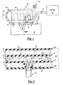
- FIG 1 illustrates an embodiment of invention 10 comprising fuel conduit 14, inner plastic wall 22, gas conduit 26, and at least one fuel injector 30.
- fuel passing from the fuel tank 12 travels through fuel conduit 14 and ultimately to fuel injector 30 and other fuel injectors of engine 50 as known.
- Gas conduit 26 envelopes fuel conduit 14. Both gas conduit 26 and fuel conduit 14 may be made of plastic.
- Fuel conduit 14 carries fuel having liquid form 38 and vapor form 42. Inner wall 22 may allow some fuel vapor 42 to escape fuel conduit 14. Gas conduit 26 may have a lower pressure than fuel conduit 14.
- fuel vapor 42 may travel through gas conduit 26 into gas reservoir 56, such as a canister or plenum volume, and along the path of arrow A into air intake manifold 46.
- a purge control device 34 such as a crankcase ventilation system, may purge the fuel vapor in gas conduit 26 and gas reservoir 56 to an acceptable destination.
- air intake manifold 46 may evenly distribute vapor 42 from gas reservoir 56 to the air intake ports of air intake manifold 46. Air and the fuel vapor channeled through gas conduit 26 are then channeled through air intake manifold 46 into the combustion chamber of the cylinder.
- air intake manifold 46 not only introduces air into combustion chamber as known but also vapor form 42 from gas conduit 26.
- Air and fuel vapor form 42 combine and combust with liquid form 38 of gas. Vapor 42 is thus consumed by engine 50 rather than permitted to escape into the environment. Gas reservoir 56 ensures distribution of vapor 42 evenly through air intake manifold 46 so as to avoid concentration of vapor 42 in a particular cylinder.
- the plenum volume of existing air intake systems may be employed with minor connection changes that may be made by one of ordinary skill in the art.
- Figure 3 illustrates a plan view of fuel conduit 14 and gas conduit 26. Shown are inner diameter wall 27 of gas conduit 26, which also serves as the wall 22 of fuel conduit 14. Outer diameter wall 28 is also shown. Fuel conduit shares a common wall 22 with gas conduit 26, and is preferably enclosed by gas conduit 26.
- Figure 4 shows a cross-section of fuel conduit 14 and gas conduit 26. As illustrated, gas conduit 26 envelopes fuel conduit 14, sharing wall 22. Fuel injector 30 is shown in communication with fuel conduit 14.
- Figure 5 illustrates a cross section of another embodiment of the invention, including fuel conduit 60 and gas conduit 64.
- gas conduit 64 does not entirely envelope fuel conduit 60.
- gas conduit has outer diameter wall 58, this wall may be formed integrally with inner wall 62, which itself serves to form fuel conduit 60.
- Fuel injector 66 is also shown communicating fuel by spray 70 into a combustion chamber (not shown) as known.
- Figure 6 illustrates another embodiment of the invention whereby gas conduit 78 shares even less of the inner wall 82 then other embodiments.
- fuel conduit 74 has wall 82, which also serves as an inner diameter wall of gas conduit 78 over a portion of conduit 78.
- Gas conduit 78 also has outer diameter wall 86.
- Fuel injector 90 with fuel spray 94 is also illustrated. The area of the cross section of the fuel conduit and gas conduit may be determined by manufacturing method and the required amount of fuel fed to the engine as known.
- Figure 7 shows another embodiment of the invention.
- gas conduit 100 only shares a portion of gas permeable wall 106.
- Wall 110 serves to direct vapor 42 for its ultimate disposal.
- Gas permeable wall 106 directs both vapor 42 and liquid form 38 to fuel injector 30.
- a portion of vapor 42 may escape into environment.
- purge control device 34 or other available device will cause vapor 42 to be drawn to gas conduit 100 more than to environment.
- This particular embodiment provides limited recapture of vapor 42 but may be easier to mold.
Landscapes
- Engineering & Computer Science (AREA)
- Chemical & Material Sciences (AREA)
- Combustion & Propulsion (AREA)
- Mechanical Engineering (AREA)
- General Engineering & Computer Science (AREA)
- Fuel-Injection Apparatus (AREA)
Abstract
Description
Claims (11)
- A fuel delivery system comprising:a permeable fuel conduit having an outer fuel wall;a gas conduit at least partially surrounding said outer fuel wall; andat least one fuel injector in communication with said fuel conduit.
- The fuel delivery system of Claim 1 wherein said fuel conduit and said gas conduit share said outer fuel wall.
- The fuel delivery system of Claim 2 wherein said gas conduit has an inner diameter wall and an outer diameter wall wherein said outer fuel wall at least partially comprises said inner diameter wall.
- The fuel delivery system of any one of Claims 1 to 3, including a purge control device in communication with said gas conduit for moving gas through said gas conduit.
- The fuel delivery system of Claim 4 wherein said purge control device comprises a crankcase ventilation system.
- The fuel delivery system of any one of Claims 1 to 5, including an air intake manifold in communication with said gas conduit.
- The fuel delivery system of any one of Claims 1 to 6, including a gas reservoir in communication with said gas conduit for collecting gas.
- The fuel delivery system of any one of the preceding Claims wherein pressure in said gas conduit is less than atmospheric.
- The fuel delivery system of Claim 8, wherein said gas conduit is formed of plastic.
- The fuel delivery system of any one of the preceding Claims, wherein the permeable fuel conduit is formed of plastic.
- The fuel delivery system in accordance with any one of the preceding Claims, wherein the permeable fuel conduit communicates a fuel in both a liquid and a vapor state; and
wherein said fuel vapor that diffuses through said outer fuel wall is captured in said gas conduit.
Applications Claiming Priority (2)
| Application Number | Priority Date | Filing Date | Title |
|---|---|---|---|
| US24318700P | 2000-10-25 | 2000-10-25 | |
| US243187P | 2000-10-25 |
Publications (3)
| Publication Number | Publication Date |
|---|---|
| EP1201909A2 true EP1201909A2 (en) | 2002-05-02 |
| EP1201909A3 EP1201909A3 (en) | 2003-01-08 |
| EP1201909B1 EP1201909B1 (en) | 2008-04-02 |
Family
ID=22917679
Family Applications (1)
| Application Number | Title | Priority Date | Filing Date |
|---|---|---|---|
| EP01203960A Expired - Lifetime EP1201909B1 (en) | 2000-10-25 | 2001-10-16 | Double walled fuel rail |
Country Status (3)
| Country | Link |
|---|---|
| US (1) | US6499466B2 (en) |
| EP (1) | EP1201909B1 (en) |
| DE (1) | DE60133444T2 (en) |
Families Citing this family (7)
| Publication number | Priority date | Publication date | Assignee | Title |
|---|---|---|---|---|
| DE19931282C1 (en) * | 1999-07-07 | 2001-01-11 | Mtu Friedrichshafen Gmbh | Fuel injection system for an internal combustion engine |
| US6732717B2 (en) * | 2002-04-17 | 2004-05-11 | Delphi Technologies, Inc. | Fuel rail permeant collection system |
| US6827065B2 (en) * | 2003-04-08 | 2004-12-07 | General Motors Corporation | Diesel injection system with dual flow fuel line |
| KR100580699B1 (en) * | 2003-10-27 | 2006-05-15 | 현대자동차주식회사 | Dual Control of Common Rail System |
| US7909024B2 (en) * | 2007-11-29 | 2011-03-22 | Martinrea International Inc. | Hydrocarbon fuel vapour filter system |
| US8844500B2 (en) | 2011-01-22 | 2014-09-30 | Cummins Intellectual Property, Inc. | Enclosure for high pressure fuel rail |
| ES2461181T3 (en) | 2011-05-31 | 2014-05-19 | Caterpillar Motoren Gmbh & Co. Kg | Double wall fuel feed line element |
Family Cites Families (10)
| Publication number | Priority date | Publication date | Assignee | Title |
|---|---|---|---|---|
| US4159698A (en) * | 1977-03-09 | 1979-07-03 | Las Vegas Research, Inc. | Anti-pollution method and apparatus for combustion engines |
| US5076242A (en) * | 1990-07-18 | 1991-12-31 | Illinois Tool Works Inc. | Integral fuel line |
| DE4115039A1 (en) * | 1991-05-08 | 1992-11-12 | Bosch Gmbh Robert | FUEL DISTRIBUTOR |
| GB2258694A (en) * | 1991-08-15 | 1993-02-17 | Ford Motor Co | I.c.engine fuel supply and return pipe arrangment. |
| US5239964A (en) * | 1992-05-11 | 1993-08-31 | Illinois Tool Works Inc. | Concentric fuel line system |
| JP2812102B2 (en) * | 1992-10-15 | 1998-10-22 | 株式会社デンソー | Fuel supply device for internal combustion engine |
| FR2704601B1 (en) * | 1993-04-26 | 1995-07-13 | Renault | Air supply system for fuel injectors of the air mantle type fitted to an internal combustion engine. |
| GB9415950D0 (en) * | 1994-08-06 | 1994-09-28 | Rover Group | A fuel feed system for an internal combustion engine |
| JP3720402B2 (en) * | 1995-02-17 | 2005-11-30 | ヤマハマリン株式会社 | Fuel-injection outboard motor |
| DE19534050A1 (en) * | 1995-09-14 | 1997-03-20 | Bosch Gmbh Robert | Fuel injection system for internal combustion engines |
-
2001
- 2001-10-02 US US09/969,419 patent/US6499466B2/en not_active Expired - Lifetime
- 2001-10-16 DE DE60133444T patent/DE60133444T2/en not_active Expired - Lifetime
- 2001-10-16 EP EP01203960A patent/EP1201909B1/en not_active Expired - Lifetime
Also Published As
| Publication number | Publication date |
|---|---|
| EP1201909B1 (en) | 2008-04-02 |
| US6499466B2 (en) | 2002-12-31 |
| DE60133444D1 (en) | 2008-05-15 |
| DE60133444T2 (en) | 2009-04-09 |
| EP1201909A3 (en) | 2003-01-08 |
| US20020046735A1 (en) | 2002-04-25 |
Similar Documents
| Publication | Publication Date | Title |
|---|---|---|
| US4070828A (en) | Device and method for recycling hydrocarbon vapors of I.C.E. vehicles | |
| US6499466B2 (en) | Double walled fuel rail | |
| US5779879A (en) | Apparatus and method for reducing harmful substances in combustion gases | |
| US20010039881A1 (en) | Canister | |
| US7827974B2 (en) | Method for operating an internal combustion engine of a vehicle, especially a motor vehicle, and device for implementing said method | |
| SE9500912L (en) | Ventilation device for a fuel system for an internal combustion engine | |
| US6438486B1 (en) | System and method for minimizing fuel evaporative emissions from an internal combustion engine | |
| US7146970B2 (en) | Integrated vapor control valve and sensor | |
| KR980008693A (en) | Evaporative gas control device of fuel tank | |
| US6634342B1 (en) | Fuel system for a vehicle | |
| EP0810367A3 (en) | An evaporated fuel processing apparatus for an internal combustion engine | |
| US7004151B2 (en) | Vented injector cup | |
| US6883500B2 (en) | Fuel pump module with improved vapor vent manifold | |
| US20210270212A1 (en) | Tank ventilation | |
| US6732717B2 (en) | Fuel rail permeant collection system | |
| EP1020634A3 (en) | A method for anticipating variations in the level of purge vapors | |
| JP2962166B2 (en) | Fuel evaporation prevention device | |
| US5983870A (en) | Adsorption filter for the fuel tank venting system of an internal combustion engine and process for operating said system | |
| JPH0942080A (en) | Canister | |
| JP2962167B2 (en) | Fuel evaporation prevention device | |
| JPH09209849A (en) | Evaporated fuel collection device at fueling time in vehicle | |
| US10876499B2 (en) | Purge ejector assembly for a vehicle | |
| US20050126549A1 (en) | Ventilation system for a fuel tank of an internal combustion engine | |
| JPH0893577A (en) | Evaporative fuel processor | |
| JP2002235609A (en) | Evaporative fuel treatment system for a supercharged internal combustion engine |
Legal Events
| Date | Code | Title | Description |
|---|---|---|---|
| PUAI | Public reference made under article 153(3) epc to a published international application that has entered the european phase |
Free format text: ORIGINAL CODE: 0009012 |
|
| AK | Designated contracting states |
Kind code of ref document: A2 Designated state(s): AT BE CH CY DE DK ES FI FR GB GR IE IT LI LU MC NL PT SE TR |
|
| AX | Request for extension of the european patent |
Free format text: AL;LT;LV;MK;RO;SI |
|
| PUAL | Search report despatched |
Free format text: ORIGINAL CODE: 0009013 |
|
| AK | Designated contracting states |
Kind code of ref document: A3 Designated state(s): AT BE CH CY DE DK ES FI FR GB GR IE IT LI LU MC NL PT SE TR |
|
| AX | Request for extension of the european patent |
Free format text: AL;LT;LV;MK;RO;SI |
|
| 17P | Request for examination filed |
Effective date: 20021211 |
|
| AKX | Designation fees paid |
Designated state(s): DE FR GB |
|
| RAP1 | Party data changed (applicant data changed or rights of an application transferred) |
Owner name: SIEMENS VDO AUTOMOTIVE INC. |
|
| 17Q | First examination report despatched |
Effective date: 20060116 |
|
| GRAP | Despatch of communication of intention to grant a patent |
Free format text: ORIGINAL CODE: EPIDOSNIGR1 |
|
| GRAS | Grant fee paid |
Free format text: ORIGINAL CODE: EPIDOSNIGR3 |
|
| GRAA | (expected) grant |
Free format text: ORIGINAL CODE: 0009210 |
|
| AK | Designated contracting states |
Kind code of ref document: B1 Designated state(s): DE FR GB |
|
| REG | Reference to a national code |
Ref country code: GB Ref legal event code: FG4D |
|
| REF | Corresponds to: |
Ref document number: 60133444 Country of ref document: DE Date of ref document: 20080515 Kind code of ref document: P |
|
| ET | Fr: translation filed | ||
| PLBE | No opposition filed within time limit |
Free format text: ORIGINAL CODE: 0009261 |
|
| STAA | Information on the status of an ep patent application or granted ep patent |
Free format text: STATUS: NO OPPOSITION FILED WITHIN TIME LIMIT |
|
| 26N | No opposition filed |
Effective date: 20090106 |
|
| REG | Reference to a national code |
Ref country code: FR Ref legal event code: PLFP Year of fee payment: 15 |
|
| REG | Reference to a national code |
Ref country code: FR Ref legal event code: PLFP Year of fee payment: 16 |
|
| REG | Reference to a national code |
Ref country code: DE Ref legal event code: R084 Ref document number: 60133444 Country of ref document: DE |
|
| REG | Reference to a national code |
Ref country code: FR Ref legal event code: PLFP Year of fee payment: 17 |
|
| REG | Reference to a national code |
Ref country code: FR Ref legal event code: PLFP Year of fee payment: 18 |
|
| PGFP | Annual fee paid to national office [announced via postgrant information from national office to epo] |
Ref country code: GB Payment date: 20181031 Year of fee payment: 18 Ref country code: FR Payment date: 20181030 Year of fee payment: 18 |
|
| PGFP | Annual fee paid to national office [announced via postgrant information from national office to epo] |
Ref country code: DE Payment date: 20181228 Year of fee payment: 18 |
|
| REG | Reference to a national code |
Ref country code: DE Ref legal event code: R119 Ref document number: 60133444 Country of ref document: DE |
|
| PG25 | Lapsed in a contracting state [announced via postgrant information from national office to epo] |
Ref country code: DE Free format text: LAPSE BECAUSE OF NON-PAYMENT OF DUE FEES Effective date: 20200501 |
|
| GBPC | Gb: european patent ceased through non-payment of renewal fee |
Effective date: 20191016 |
|
| PG25 | Lapsed in a contracting state [announced via postgrant information from national office to epo] |
Ref country code: FR Free format text: LAPSE BECAUSE OF NON-PAYMENT OF DUE FEES Effective date: 20191031 Ref country code: GB Free format text: LAPSE BECAUSE OF NON-PAYMENT OF DUE FEES Effective date: 20191016 |