EP1201894A2 - Mécanisme pour la variation des taux de compression d' un moteur à combustion interne - Google Patents
Mécanisme pour la variation des taux de compression d' un moteur à combustion interne Download PDFInfo
- Publication number
- EP1201894A2 EP1201894A2 EP01124546A EP01124546A EP1201894A2 EP 1201894 A2 EP1201894 A2 EP 1201894A2 EP 01124546 A EP01124546 A EP 01124546A EP 01124546 A EP01124546 A EP 01124546A EP 1201894 A2 EP1201894 A2 EP 1201894A2
- Authority
- EP
- European Patent Office
- Prior art keywords
- slider
- compression ratio
- hydraulic pressure
- reciprocating
- pressure chamber
- Prior art date
- Legal status (The legal status is an assumption and is not a legal conclusion. Google has not performed a legal analysis and makes no representation as to the accuracy of the status listed.)
- Granted
Links
Images


Classifications
-
- F—MECHANICAL ENGINEERING; LIGHTING; HEATING; WEAPONS; BLASTING
- F02—COMBUSTION ENGINES; HOT-GAS OR COMBUSTION-PRODUCT ENGINE PLANTS
- F02B—INTERNAL-COMBUSTION PISTON ENGINES; COMBUSTION ENGINES IN GENERAL
- F02B75/00—Other engines
- F02B75/04—Engines with variable distances between pistons at top dead-centre positions and cylinder heads
- F02B75/048—Engines with variable distances between pistons at top dead-centre positions and cylinder heads by means of a variable crank stroke length
-
- F—MECHANICAL ENGINEERING; LIGHTING; HEATING; WEAPONS; BLASTING
- F02—COMBUSTION ENGINES; HOT-GAS OR COMBUSTION-PRODUCT ENGINE PLANTS
- F02B—INTERNAL-COMBUSTION PISTON ENGINES; COMBUSTION ENGINES IN GENERAL
- F02B75/00—Other engines
- F02B75/04—Engines with variable distances between pistons at top dead-centre positions and cylinder heads
- F02B75/045—Engines with variable distances between pistons at top dead-centre positions and cylinder heads by means of a variable connecting rod length
Definitions
- the present invention relates to the improvements of a variable compression ratio mechanism for a reciprocating internal combustion engine.
- 11" is comprised of an upper link mechanically linked at one end to a piston pin, a lower link mechanically linked to both the upper link and a crankpin of an engine crankshaft, a control shaft arranged essentially parallel to the axis of the crankshaft and having an eccentric cam whose axis is eccentric to the axis of the control shaft, and a control link rockably or oscillatingly linked at one end onto the eccentric cam of the control shaft and linked at the other end to the lower end of the upper link.
- the other end of the control link may be linked to the lower link, instead of linking the control link to the upper link.
- the compression ratio is set at a relatively low value at high-load operation to avoid undesired engine knocking from occurring. Conversely, at part-load operation, the compression ratio is set at a relatively high value to enhance the combustion efficiency.
- a control-shaft actuator In order to produce the rotary motion of the control shaft, a control-shaft actuator is used.
- the control-shaft actuator is often comprised of a control screw portion and a control nut portion engaged with each other.
- an external screw-threaded portion serving as the control screw portion
- an internal screw-threaded portion serving as the control nut portion
- a cylindrical member of the actuator When the cylindrical member is driven in its one rotational direction by means of a power source such as an electric motor or a hydraulic pump, one axial sliding movement of the reciprocating block slider occurs by way of the control screw portion and the control nut portion.
- the reciprocating load mostly acts in a principal direction, that is, in a direction of the force acting on the reciprocating block slider owing to the piston combustion load.
- the reciprocating load tends to act in a direction opposite to the principal direction. If the direction of reciprocating load acting on the reciprocating block slider is reversed, there is an increased tendency for the reciprocating block slider to oscillate within a backlash (defined between the internal and external screw-threaded portions) axially relative to the cylindrical member (rotary member) of the actuator.
- variable compression ratio mechanism for a reciprocating internal combustion engine, which avoids or suppresses hammering noise and vibration to occur owing to a backlash defined between internal and external screw-threaded portions being in meshed-engagement with each other and constructing part of a control-shaft actuator.
- variable compression ratio mechanism for a reciprocating internal combustion engine including a piston moveable through a stroke in the engine and having a piston pin and a crankshaft changing reciprocating motion of the piston into rotating motion and having a crankpin
- the variable compression ratio mechanism comprises a plurality of links mechanically linking the piston pin to the crankpin, a control shaft to which an eccentric cam is attached so that a center of the eccentric cam is eccentric to a center of the control shaft, a control link connected at one end to one of the plurality of links and connected at the other end to the eccentric cam, and an actuator that drives the control shaft within a predetermined controlled angular range and holds the control shaft at a desired angular position so that a compression ratio of the engine continuously reduces by driving the control shaft in a first rotational direction and so that the compression ratio continuously increases by driving the control shaft in a second rotational direction opposite to the first rotational direction
- the actuator comprising a reciprocating block slider linked at a first end portion to the
- a cylinder block 11 includes engine cylinders 12, each consisting of a cylindrical design featuring a smoothly finished inner wall that forms a combustion chamber in combination with a piston 14 and a cylinder head (not shown).
- a water jacket 13 is formed in the cylinder block in such a manner as to surround each engine cylinder.
- Cylinder 12 serves as a guide for reciprocating motion of piston 14.
- a piston pin 15 of each of the pistons and a crankpin 17 of an engine crankshaft 16 are mechanically linked to each other by means of a multiple-link type variable compression ratio mechanism (or a multiple-link type piston crank mechanism).
- reference sign 18 denotes a counterweight.
- the linkage of the multiple-link type variable compression ratio mechanism is comprised of three links, namely a lower link 21, a rod-shaped upper link 22, and a control link 25.
- Lower link 21 is fitted onto the outer periphery of crankpin 17 in a manner so as to permit relative rotation of lower link 21 to crankpin 17.
- Upper link 22 is provided to mechanically link the lower link therevia to the piston pin.
- the variable compression ratio mechanism of the embodiment also includes a control shaft 23 extending parallel to the axis of crankshaft 16, that is, arranged in a direction parallel to the cylinder row, and an eccentric cam 24 attached to the control shaft so that the center of eccentric cam 24 is eccentric to the center of control shaft 23.
- Eccentric cam 24 and lower link 21 are mechanically linked to each other through control link 25.
- a control-shaft actuator 30 (drive means) is provided to rotate or drive control shaft 23 within a predetermined controlled angular range and to hold the control shaft at a desired angular position.
- the upper end portion of rod-shaped upper link 22 is linked to piston pin 15 in a manner so as to permit relative rotation of upper link 22 to piston pin 15.
- the lower end portion of rod-shaped upper link 22 is linked or pin-connected to lower link 21 by way of a connecting pin 26, in a manner so as to permit relative rotation of upper link 22 to lower link 21.
- One end (the upper end) of control link 25 is linked or pin-connected to lower link 21 by way of a connecting pin 27, for relative rotation.
- Actuator 30 includes a substantially cylindrical actuator casing 31 fixedly connected to cylinder block 11, a reciprocating block slider (or a reciprocating piston) 32 that reciprocates in the actuator casing 31, and a substantially cylindrical rotary member 34 being meshed-engagement with the rear end portion of reciprocating block slider 32 by means of a meshing pair of screw-threaded portions (33a, 33b).
- a substantially cylindrical actuator casing 31 fixedly connected to cylinder block 11
- a reciprocating block slider (or a reciprocating piston) 32 that reciprocates in the actuator casing 31
- a substantially cylindrical rotary member 34 being meshed-engagement with the rear end portion of reciprocating block slider 32 by means of a meshing pair of screw-threaded portions (33a, 33b).
- an external screw-threaded portion 33a is formed on the outer periphery of the substantially rod-like, rear end portion of reciprocating block slider 32, whereas an internal screw-threaded portion 33b is formed on the inner periphery of substantially cylindrical rotary member 34, so that the internal and external screw-threaded portions 33b and 33a are in meshed-engagement with each other.
- a predetermined backlash 33c i.e., a predetermined axial clearance
- reciprocating block slider 32 is arranged in a direction normal to the axis of control shaft 23 in such a manner as to reciprocate in the actuator casing 31 in the axial direction of reciprocating block slider 32.
- a pin 35 is attached to the tip end portion (the front end portion) of reciprocating block slider 32 so that the axis of pin 35 is arranged in a direction perpendicular to the axial direction of reciprocating block slider 32.
- a control plate 36 is attached to one end of control shaft 23 and has a radially extending slit 37. Pin 35 of reciprocating block slider 32 is slidably fitted into slit 37 of control plate 36.
- Rotary member 34 is rotatably supported in actuator casing 31 by means of bearings 38 in a manner so as to rotate about its axis.
- An output shaft 39 of a power source such as an electric motor is fixedly connected to one end of rotary member 34.
- the electric motor is used as a power source.
- a hydraulic pump may be used as a power source.
- rotary member 34 In response to a control signal from an electronic engine control unit often abbreviated to "ECU" (not shown), rotary member 34 can be rotated or driven about its axis via the output shaft 34 of the power source.
- the control signal value of the ECU is dependent upon engine operating conditions such as engine speed and load.
- a hydraulic pressure chamber 40 is formed in actuator casing 31 of actuator 30 so that hydraulic pressure chamber 40 faces the rear axial end face 32a of reciprocating block slider 32.
- hydraulic pressure chamber 40 is defined by the inner peripheral wall surface of rotary member 34, the rear axial end face 32a of reciprocating block slider 32, and a cap portion 34a attached to the connecting end of output shaft 39 fixedly connected to rotary member 34.
- Cap portion 34a serves to plug up the opening end of substantially cylindrical rotary member 34 in a fluid-tight fashion.
- a hydraulic modulator is provided to control or regulate the hydraulic pressure in hydraulic pressure chamber 40.
- the hydraulic modulator is comprised of a working-fluid supply passage 42, an oil pump 43 serving as a hydraulic pressure source, and a one-way check valve 44.
- Supply passage 42 is provided to supply working fluid reserved in an oil pan 41 into hydraulic pressure chamber 40.
- Check valve 44 is fluidly disposed between oil pump 43 and hydraulic pressure chamber 40 so as to check or prevent back flow of working fluid from hydraulic pressure chamber 40 toward oil pump 43.
- Supply passage 42 includes a substantially annular circumferential groove 45 formed or recessed in the inner periphery of substantially cylindrical actuator casing 31, and a first one of a pair of radial through holes (46, 46) formed in substantially cylindrical rotary member 34 in such a manner that circumferential groove 45 is communicated with hydraulic pressure chamber 40 through the first radial through hole 46.
- the hydraulic modulator also includes a working-fluid drain passage 47 and a hydraulic pressure regulating valve 48.
- Drain passage 47 is provided to drain the working fluid from hydraulic pressure chamber 40 into oil pan 41.
- Hydraulic pressure regulating valve 48 is fluidly disposed in drain passage 47 to regulate or adjust the hydraulic pressure in hydraulic pressure chamber 40 or the hydraulic pressure in drain passage 47.
- Hydraulic pressure regulating valve 48 also serves as a pressure relief valve that opens when a predetermined pressure is reached, to prevent the hydraulic pressure in hydraulic pressure chamber 40 from excessively developing.
- Drain passage 47 includes both the previously-noted circumferential groove 45 and the second radial through hole 46.
- actuator 30 is designed or constructed so that undesirable reciprocating motion of the reciprocating block slider is prevented by way of meshed-engagement between internal screw-threaded portion 33b of rotary member 34 and external screw-threaded portion 33a of reciprocating block slider 32, and so that rotary motion of rotary member 34 is converted into reciprocating motion of reciprocating block slider 32.
- the power-transmission mechanism of actuator 30 is constructed as an irreversible power-transmission mechanism containing the meshing pair of screw-threaded portions (33a, 33b) disposed between rotary member 34 and reciprocating block slider 32. In this manner, the center of oscillating motion of control link 25 fitted onto eccentric cam 24 can be varied by rotating control shaft 23 depending on engine operating conditions.
- variable compression ratio mechanism of the embodiment piston pin 15 and crankshaft 16 are mechanically linked by means of only two links, namely upper and lower links 22 and 21. Therefore, the variable compression ratio mechanism of the embodiment is simple in construction, as compared to a multiple-link type variable compression ratio mechanism comprised of three or more links.
- control link 25 is connected to lower link 21, but not connected to upper link 22. Thus, control link 25 and control shaft 23 can be laid out within a comparatively wide space defined in the lower portion of the engine. Thus, it is possible to easily mount the variable compression ratio mechanism of the embodiment in the engine.
- Reciprocating load N mostly acts in a principal direction, that is, in a direction P of the force acting on the reciprocating block slider during down stroke of the piston owing to piston combustion load Fp (see the direction P indicated in Fig. 2).
- piston combustion load Fp is less and inertial load is great, as appreciated from the waveform of reciprocating load N indicated by the broken line in Fig. 3, there is a possibility that the reciprocating load acts in a direction opposite to the principal direction P (see the opposite direction P' in Fig. 3).
- variable compression ratio mechanism of the embodiment is constructed so that reciprocating block slider 32 is biased in the same direction as the principal direction P of the reciprocating load by virtue of the working-fluid pressure in hydraulic pressure chamber 40. That is, hydraulic pressure chamber 40 is constructed to face the previously-noted reciprocating-block-slider rear axial end face 32a facing in the opposite direction P' (see Fig. 2), so that the hydraulic pressure in hydraulic pressure chamber 40 is applied onto reciprocating-block-slider rear axial end face 32a.
- control shaft 23 rotates in the direction of the low compression ratio.
- the direction of reciprocating load N is always maintained in the principal direction P. That is, in the presence of application of hydraulic pressure properly regulated and acting on reciprocating-block-slider rear axial end face 32a, there is no risk of reversing the direction of the reciprocating load owing to the piston combustion load Fp and inertial load of each of links. That is, the hydraulic pressure in hydraulic pressure chamber 40 is set or regulated to a predetermined pressure level (or a set pressure value) that reversal of the direction of reciprocating load N never occurs. During application of the hydraulic pressure regulated to the predetermined pressure level, as shown in Fig.
- the face of tooth of reciprocating-block-slider external screw-threaded portion 33a facing in the principal direction P is constantly pressed against the face of tooth of rotary-member internal screw-threaded portion 33b facing in the opposite direction P'.
- a portion of working fluid in hydraulic pressure chamber 40 can be fed into the tooth space between the meshing pair of screw-threaded portions (33a, 33b), for good lubrication of the face of tooth and enhanced durability.
- the hydraulic modulator has the check valve 44 fluidly disposed in supply passage 42 and between oil pump 43 and hydraulic pressure chamber 40. By the use of check valve 44, it is possible to certainly prevent counter-flow of working fluid in hydraulic pressure chamber 40 back to oil pump 43.
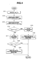
- Fig. 4 there is shown the control routine needed to control the opening and closing of hydraulic pressure regulating valve 48 and the operation of the power source (electric motor) for control-shaft actuator 30.
- the routine shown in Fig. 4 is executed as time-triggered interrupt routines to be triggered every predetermined time intervals.
- step S11 engine speed Ne, an intake-air quantity Qa, and a phase angle ⁇ cs of control shaft 23 are read.
- a target compression ratio ⁇ goal is arithmetically calculated based on both engine speed Ne and intake-air quantity Qa.
- an actual compression ratio ⁇ now is arithmetically calculated based on phase angle ⁇ cs of control shaft 23.
- step S14 a check is made to determine whether target compression ratio ⁇ goal is greater than actual compression ratio ⁇ now .
- the routine proceeds from step S14 to step S15.
- step S15 hydraulic pressure regulating valve 48 is opened, and as a result a part of the working fluid in hydraulic pressure chamber 40 is properly exhausted into oil pan 41, thus avoiding an excessive rise in hydraulic pressure in pressure chamber 40. Thereafter, the routine flows from step S15 to step S16.
- step S16 output shaft 39 of the power source (motor) is rotated or driven in the high-compression-ratio rotational direction.
- step S17 hydraulic pressure regulating valve 48 is closed, and as a result the working fluid in hydraulic pressure chamber 40 is not exhausted via drain passage 47 into oil pan 41, but properly charged or stored in hydraulic pressure chamber 40.
- step S14 when the reciprocating block slider has to be maintained at the current axial position, that is, when the volume in hydraulic pressure chamber 40 has to be held constant, the routine proceeds from step S14 to step S17, and therefore hydraulic pressure regulating valve 48 is closed. As a result, the working fluid in hydraulic pressure chamber 40 is not exhausted via drain passage 47 into oil pan 41, and thus a pressure drop in the hydraulic pressure in pressure chamber 40 is suppressed.
- step S18 occurs.
- step S19 output shaft 39 of the power source (motor) is rotated or driven in the low-compression-ratio rotational direction.
- the predetermined pressure level of the hydraulic pressure in pressure chamber 40 is determined depending on the discharge pressure of working fluid discharged from oil pump 43.
- the set pressure value of working fluid in hydraulic pressure chamber 40 may be set to a pressure value higher than the discharge pressure of oil pump 43. In this case, the set pressure value higher than the discharge pressure of oil pump 43 can be obtained by shifting the reciprocating block slider to the high-compression-ratio direction under a condition wherein hydraulic pressure regulating valve is closed and thus the working fluid in sealed up in pressure chamber 40.
- FIGs. 5 through 8 there are shown waveforms of control-shaft torque T in a four-cylinder engine.
- a particular condition in which control-shaft torque T acting on control shaft 23 is reversed that is, the direction of reciprocating load N acting on reciprocating block slider 32 is reversed
- the torque value of input torque acting on control shaft 23 is changed from positive to negative
- Figs. 5 - 8 the x-axis (abscissa) indicates a crank angle (unit: degrees)
- the y-axis (ordinate) indicates control-shaft torque T acting on control shaft 23
- #1TCS indicates the control-shaft torque occurring in No.
- crankshaft 16 corresponding to 0° crankangle is defined as a specified state wherein the axis of crankpin 17 is aligned with the axis of crankshaft 16 in the major thrust direction or in the minor thrust direction.
- the direction of action of control-shaft torque T created when the downward piston combustion load Fp acts on the piston crown of piston 14, that is, the clockwise direction (see the direction of action of torque T shown in Fig. 1) is defined as a positive direction.
- the counterclockwise direction is defined as a negative direction. That is to say, when control-shaft torque T is positive and thus the direction of action of control-shaft torque T is the positive direction, the reciprocating load acts on reciprocating block slider 32 in the principal direction P. Conversely when control-shaft torque T is negative and thus the direction of action of control-shaft torque T is the negative direction, the reciprocating load acts on reciprocating block slider 32 in the opposite direction P'. As seen in Fig. 2, the reciprocating load acting on reciprocating block slider 32 in the principal direction P is denoted by "N”, while the reciprocating load acting on reciprocating block slider 32 in the opposite direction P' is denoted by "N' ". Figs.
- control-shaft torque becomes maximum every 90° crankangle at which the piston of each cylinder passes through TDC.
- control-shaft torque becomes minimum at every crankangle being offset from the crankangle corresponding to the maximum control-shaft torque by approximately 45 degrees.
- the decrease in control-shaft torque T mainly arises from the increase in inertial load acting on the piston in the direction opposite to the direction of action of piston combustion load Fp. The inertial load tends to increase, as the engine speed increases.
- the minimum torque value of the total control-shaft torque is a positive value.
- the direction of action of control-shaft torque T is the positive direction, that is, the low-compression-ratio direction, and thus there is no risk of reversing the direction of action of control-shaft torque T (i.e., the direction of reciprocating load N).
- predetermined low engine speed ⁇ which reversal of the direction of reciprocating load N (i.e., reversal of the direction of action of control-shaft torque T) never occurs, varies depending on both the engine load and phase angle ⁇ cs of control shaft 23.
- control-shaft torque T i.e., the direction of reciprocating load N
- the absolute value of the negative minimum torque value of total control-shaft torque TOTAL TCS tends to increase, as the engine speed increases from 4000 rpm (see Fig. 6) via 5000 rpm (see Fig. 7) to 6000 rpm (see Fig. 8).
- hydraulic pressure regulating valve 48 is closed, so as to produce a relatively high hydraulic pressure enough to avoid undesirable reversal of the direction of reciprocating load N (i.e., undesirable reversal of the direction of action of control-shaft torque T).
- Fig. 9 shows the modified control routine needed to control the opening and closing of hydraulic pressure regulating valve 48 and the operation of the power source (electric motor) for control-shaft actuator 30, taking account of whether the engine is operating in or out of the predetermined engine speed range above predetermined low engine speed ⁇ .
- the modified control routine of Fig. 9 is similar to the routine of Fig. 4, except that step S17 included in the routine shown in Fig. 4 is replaced with steps S27, S28, S29 and S30 included in the modified routine shown in Fig. 9.
- step S17 included in the routine shown in Fig. 4 is replaced with steps S27, S28, S29 and S30 included in the modified routine shown in Fig. 9.
- Steps S21, S22, S23, S24, S25, S26, S31, and S32 shown in Fig. 9 correspond to the respective steps S11, S12, S13, S14, S15, S16, S18, and S19 shown in Fig. 4.
- Steps S27, S28, S29 and S30 will be hereinafter described in detail with reference to the accompanying drawings, while detailed description of steps S21 through S26, S31 and S32 will be omitted because the above description thereon seems to be self-explanatory.
- step S24 When the answer to step S24 is affirmative ( ⁇ goal > ⁇ now ), that is, when shifting of the reciprocating block slider to the direction of the high compression ratio is required (in other words, when a decrease in the volume in hydraulic pressure chamber 40 is required), the routine proceeds from step S24 to step S25, so as to open hydraulic pressure regulating valve 48. As a result, a part of the working fluid in hydraulic pressure chamber 40 is properly exhausted into oil pan 41, thus avoiding an excessive rise in hydraulic pressure in pressure chamber 40. Thereafter, at step S26, output shaft 39 of the power source (motor) is rotated or driven in the high-compression-ratio rotational direction.
- step S24 the routine proceeds from step S24 to step S27.
- step S27 the waveform of control-shaft torque T is calculated or estimated on the basis of engine operating conditions, in particular engine speed Ne (see Figs. 5 through 8).
- step S28 a check is made to determine whether control-shaft torque T acting in the opposite direction P' (in the direction of the high compression ratio) exists, that is, whether the direction of action of control-shaft torque T is reversed.
- a check is made to determine whether the engine is operating in the engine speed range above predetermined low engine speed ⁇ for example 3000 rpm.
- step S29 hydraulic pressure regulating valve 48 is closed, and as a result the working fluid in hydraulic pressure chamber 40 is not exhausted via drain passage 47 into oil pan 41, thus effectively preventing or suppressing a drop in working-fluid pressure in hydraulic pressure chamber 40.
- step S28 determines that the direction of action of control-shaft torque T is not reversed
- the routine proceeds from step S28 to step S30.
- step S30 hydraulic pressure regulating valve 48 is opened, and as a result an undesirable pressure rise in the working fluid in hydraulic pressure chamber 40 is avoided.
- step S31 occurs.
- one cycle of the control routine terminates.
- step S31 is in the negative ( ⁇ goal ⁇ ⁇ now )
- step S32 so as to drive the output shaft of the power source (motor) in the low-compression-ratio rotational direction.
- hydraulic pressure regulating valve 48 is opened irrespective of whether the variable compression ratio mechanism is operated in a low-to-high compression ratio changing mode wherein the engine compression ratio is changed from low to high, in a high-to-low compression ratio changing mode wherein the engine compression ratio is changed from high to low, or in a hold compression ratio mode wherein the engine compression ratio is held constant (see Fig. 10).
- hydraulic pressure regulating valve 48 is closed when the variable compression ratio mechanism is operated in the high-to-low compression ratio changing mode or in the hold compression ratio mode, but opened when the variable compression ratio mechanism is operated in the low-to-high compression ratio changing mode (see Fig. 10).
- the variable compression ratio mechanism of the embodiment it is possible to effectively prevent reversal of the direction of action of control-shaft torque T depending on the engine speed Ne, by properly rising the working-fluid pressure in hydraulic pressure chamber 40 in accordance with an increase in the engine speed.
- oil pump 43 constructed as a mechanical oil pump which is mechanically linked to engine crankshaft 16 so that the oil pump is driven by way of rotation of crankshaft 16, since a driving force of oil pump 43 increases as the engine speed increases and therefore the working-fluid pressure in hydraulic pressure chamber 40 also rises in accordance with the increase in the engine speed.
- Fig. 11 shows the cross section of the multiple-link type variable compression ratio mechanism of the second embodiment
- Fig. 12 shows the cross section of the multiple-link type variable compression ratio mechanism of the third embodiment.
- the variable compression ratio mechanism of each of the second and third embodiments is similar to the first embodiment of Fig. 1.
- the same reference signs used to designate elements in the mechanism of the first embodiment shown in Fig. 1 will be applied to the corresponding reference signs used in the mechanism of each of the second and third embodiments, for the purpose of comparison among the first, second, and third embodiments.
- Detailed description of the same elements will be omitted because the above description thereon seems to be self-explanatory.
- variable compression ratio mechanism of the second embodiment shown in Fig. 11 is different from that of the first embodiment shown in Fig. 1, in that a spring 50 is further provided and thus reciprocating block slider 32 is spring-biased.
- spring 50 is disposed between reciprocating-block-slider rear axial end face 32a and cap portion 34a in a properly compressed state, in a manner so as to bias reciprocating block slider 32 in the same direction as the direction that the reciprocating block slider is forced by way of the working-fluid pressure in hydraulic pressure chamber 40.
- the pushing force applied to reciprocating block slider 32 by way of hydraulic pressure in pressure chamber 40 may be decreased.
- spring 50 is very useful. By optimizing the pushing force applied to reciprocating block slider 32 by way of both spring bias and hydraulic pressure, it is possible to certainly prevent reversal of the direction of reciprocating load N acting on reciprocating block slider 32.
- control-shaft actuator 30' incorporated in the variable compression ratio mechanism of the third embodiment shown in Fig. 12 is different from the structure of actuator 30 incorporated in the mechanism of the first embodiment shown in Fig. 1, as described hereunder.
- a rotary member 34' is not cylindrical, and in lieu thereof the rear end portion of a reciprocating block slider 32' is formed as a substantially cylindrical portion.
- Rotary member 34' fixedly connected to the output shaft of the power source (motor) is substantially rod-shaped and has an external screw-threaded portion 33a' formed on the outer periphery thereof.
- an internal screw-threaded portion 33b' is formed on the inner periphery of the substantially cylindrical rear end portion of reciprocating block slider 32', such that internal screw-threaded portion 33b' is in meshed-engagement with external screw-threaded portion 33a'.
- Working fluid is supplied into the tooth space between the meshing pair of screw-threaded portions (33a', 33b') through a circumferential groove 45' formed in the inner periphery of a substantially cylindrical actuator casing 31' and a pair of radial through holes (46', 46') formed in the substantially cylindrical rear end portion of reciprocating block slider 32'. Then, a part of the working fluid supplied into the tooth space between the meshing pair of screw-threaded portions (33a', 33b') is returned via an auxiliary hydraulic pressure chamber 51 defined in the closed end of substantially cylindrical actuator casing 31' and an auxiliary working-fluid drain passage 52 communicating auxiliary hydraulic pressure chamber 51 into drain passage 47 downstream of hydraulic pressure regulating valve 48.
- actuator 30 of the first embodiment of Fig. 1 in order to smoothly rotate substantially cylindrical rotary member 34 (loosely fitted into the axial bore defined in actuator casing 31) about its axis, the rotary member has to be supported by means of bearings.
- actuator 30' of the third embodiment of Fig. 12 the substantially cylindrical rear end portion of reciprocating block slider 32' is loosely fitted into the axial bore defined in actuator casing 31'.
- the substantially cylindrical rear end portion of reciprocating block slider 32' is not rotated, but axially slid. This eliminates the necessity of bearings, and thus actuator 30' of the third embodiment is simple in construction.
- rotary member 34' can be small-sized, because rotary member 34' is constructed as a rod-shaped male screw-threaded portion fixed to the output shaft of the power source (motor). This contributes to a reduction in the moment of inertia of the rotary member with respect to its axis, thus enhancing the response of switching between two different compression ratios.
Applications Claiming Priority (2)
| Application Number | Priority Date | Filing Date | Title |
|---|---|---|---|
| JP2000332254 | 2000-10-31 | ||
| JP2000332254A JP3879385B2 (ja) | 2000-10-31 | 2000-10-31 | 内燃機関の可変圧縮比機構 |
Publications (3)
| Publication Number | Publication Date |
|---|---|
| EP1201894A2 true EP1201894A2 (fr) | 2002-05-02 |
| EP1201894A3 EP1201894A3 (fr) | 2003-04-23 |
| EP1201894B1 EP1201894B1 (fr) | 2007-04-18 |
Family
ID=18808484
Family Applications (1)
| Application Number | Title | Priority Date | Filing Date |
|---|---|---|---|
| EP01124546A Expired - Lifetime EP1201894B1 (fr) | 2000-10-31 | 2001-10-12 | Mécanisme pour la variation des taux de compression d'un moteur à combustion interne |
Country Status (4)
| Country | Link |
|---|---|
| US (1) | US6604495B2 (fr) |
| EP (1) | EP1201894B1 (fr) |
| JP (1) | JP3879385B2 (fr) |
| DE (1) | DE60127919T2 (fr) |
Cited By (8)
| Publication number | Priority date | Publication date | Assignee | Title |
|---|---|---|---|---|
| EP1361350A3 (fr) * | 2002-05-09 | 2003-11-26 | Nissan Motor Company, Limited | Mécanisme des tringleries pour un moteur à combustion interne |
| EP1496219A1 (fr) * | 2003-07-08 | 2005-01-12 | HONDA MOTOR CO., Ltd. | Moteur à combustion avec taux de compression variable |
| EP1505277A1 (fr) * | 2003-08-05 | 2005-02-09 | HONDA MOTOR CO., Ltd. | Moteur à combustion interne à taux de compression variable |
| EP1674693A3 (fr) * | 2004-12-21 | 2010-06-02 | HONDA MOTOR CO., Ltd. | Moteur avec course du piston variable |
| WO2012139616A1 (fr) * | 2011-04-15 | 2012-10-18 | Daimler Ag | Dispositif de réglage permettant de régler de façon variable un taux de compression d'un moteur à combustion interne |
| WO2012143028A1 (fr) * | 2011-04-21 | 2012-10-26 | Daimler Ag | Dispositif de réglage variable d'au moins un taux de compression d'un moteur à combustion interne |
| WO2012143029A1 (fr) * | 2011-04-21 | 2012-10-26 | Daimler Ag | Moteur à combustion interne, notamment pour un véhicule à moteur, et procédé de fonctionnement d'un tel moteur à combustion interne |
| CN110159426A (zh) * | 2019-06-28 | 2019-08-23 | 长城汽车股份有限公司 | 发动机的装配方法以及发动机 |
Families Citing this family (36)
| Publication number | Priority date | Publication date | Assignee | Title |
|---|---|---|---|---|
| US6665605B2 (en) * | 2002-03-25 | 2003-12-16 | Ford Global Technologies, Llc | System and method for controlling an engine |
| JP4096700B2 (ja) * | 2002-11-05 | 2008-06-04 | 日産自動車株式会社 | 内燃機関の可変圧縮比装置 |
| US7789050B2 (en) * | 2003-12-23 | 2010-09-07 | Institut Francais Du Petrole | Device and method for varying a compression ratio of an internal combustion engine |
| FR2867515B1 (fr) * | 2004-03-11 | 2006-06-02 | Vianney Rabhi | Dispositif de reglage pour moteur a rapport volumetrique variable |
| JP4516864B2 (ja) * | 2005-03-15 | 2010-08-04 | 日産自動車株式会社 | 内燃機関の可変圧縮比装置 |
| US7270092B2 (en) * | 2005-08-12 | 2007-09-18 | Hefley Carl D | Variable displacement/compression engine |
| JP4625780B2 (ja) * | 2006-03-16 | 2011-02-02 | 日産自動車株式会社 | 内燃機関の可変圧縮比機構 |
| JP4714610B2 (ja) * | 2006-03-16 | 2011-06-29 | 日産自動車株式会社 | 内燃機関の可変圧縮比装置 |
| JP4491426B2 (ja) * | 2006-03-16 | 2010-06-30 | 日産自動車株式会社 | 内燃機関の可変圧縮比機構 |
| US8122860B2 (en) * | 2006-05-01 | 2012-02-28 | Toyota Jidosha Kabushiki Kaisha | Variable compression ratio internal combustion engine |
| US8408171B2 (en) * | 2006-09-12 | 2013-04-02 | Honda Motor Co., Ltd. | Variable stroke engine assembly |
| JP4882912B2 (ja) * | 2007-08-10 | 2012-02-22 | 日産自動車株式会社 | 可変圧縮比内燃機関 |
| JP5029290B2 (ja) * | 2007-10-29 | 2012-09-19 | 日産自動車株式会社 | 可変圧縮比エンジン |
| US7827943B2 (en) * | 2008-02-19 | 2010-11-09 | Tonand Brakes Inc | Variable compression ratio system |
| JP4924479B2 (ja) * | 2008-02-29 | 2012-04-25 | 日産自動車株式会社 | 可変圧縮比内燃機関 |
| DE102008046426A1 (de) * | 2008-09-09 | 2010-03-11 | Schaeffler Kg | Anordnung zum Verändern des Verdichtungsverhältnisses in einem Verbrennungsmotor sowie Verbrennungsmotor mit einer derartigen Anordnung |
| JP5408016B2 (ja) * | 2010-04-15 | 2014-02-05 | トヨタ自動車株式会社 | 内燃機関の制御装置 |
| JP5629603B2 (ja) | 2011-02-23 | 2014-11-26 | 本田技研工業株式会社 | 複リンク式可変ストロークエンジン |
| JP2014509716A (ja) * | 2011-04-01 | 2014-04-21 | ボーグワーナー インコーポレーテッド | アクチュエータを移動させるためのねじれエネルギーの使用 |
| DE102011100748A1 (de) | 2011-05-07 | 2012-11-08 | Daimler Ag | Stelleinrichtung zum variablen Einstellen wenigstens eines Verdichtungsverhältnisses einer Verbrennungskraftmaschine |
| DE102011100750A1 (de) | 2011-05-07 | 2012-11-08 | Daimler Ag | Stelleinrichtung zum variablen Einstellen wenigstens eines Verdichtungsverhältnisses einer Verbrennungskraftmaschine |
| DE102011100749A1 (de) | 2011-05-07 | 2012-11-08 | Daimler Ag | Stelleinrichtung zum variablen Einstellen wenigstens eines Verdichtungsverhältnisses einer Verbrennungskraftmaschine |
| DE102011103217A1 (de) | 2011-06-01 | 2012-12-06 | Daimler Ag | Getriebeeinrichtung, insbesondere für eine Stelleinrichtung zum Einstellen wenigstens eines variablen Verdichtungsverhältnisses einer Verbrennungskraftmaschine sowie Stelleinrichtung mit einer solchen Getriebeeinrichtung |
| DE102011104531A1 (de) * | 2011-06-18 | 2012-12-20 | Audi Ag | Brennkraftmaschine |
| DE102011104934A1 (de) | 2011-06-21 | 2012-12-27 | Daimler Ag | Stelleinrichtung zum variablen Einstellen eines Verdichtungsverhältnisses einer Verbrennungskraftmaschine |
| US9441483B2 (en) | 2012-08-28 | 2016-09-13 | Regents Of The University Of Minnesota | Adjustable linkage for variable displacement |
| KR101510352B1 (ko) * | 2013-12-30 | 2015-04-08 | 현대자동차 주식회사 | 가변 압축비 엔진 |
| JP6208589B2 (ja) * | 2014-02-04 | 2017-10-04 | 日立オートモティブシステムズ株式会社 | 可変圧縮比機構のアクチュエータとリンク機構のアクチュエータ |
| JP6204243B2 (ja) * | 2014-03-28 | 2017-09-27 | 本田技研工業株式会社 | 内燃機関における圧縮比可変装置 |
| FR3043720B1 (fr) * | 2015-11-17 | 2019-11-08 | MCE 5 Development | Moteur a rapport volumetrique variable |
| US10125679B2 (en) * | 2016-03-29 | 2018-11-13 | GM Global Technology Operations LLC | Independent compression and expansion ratio engine with variable compression ratio |
| US10378459B2 (en) * | 2017-03-23 | 2019-08-13 | Ford Global Technologies, Llc | Method and system for engine control |
| KR20200042755A (ko) * | 2018-10-16 | 2020-04-24 | 현대자동차주식회사 | 유압식 가변 압축 장치 |
| US10641168B1 (en) * | 2018-10-19 | 2020-05-05 | Benton Frederick Baugh | Method for variable displacement engine |
| KR102644371B1 (ko) * | 2018-12-06 | 2024-03-07 | 현대자동차주식회사 | Ev차량 드라이빙 사운드 제어장치 및 제어방법 |
| CN114856838B (zh) * | 2022-04-02 | 2023-03-17 | 辽宁工程技术大学 | 一种自控调节汽油机用可变压缩比机构 |
Citations (5)
| Publication number | Priority date | Publication date | Assignee | Title |
|---|---|---|---|---|
| GB379169A (en) * | 1931-12-02 | 1932-08-25 | Otto Severin Ruud | Improvements in the driving gear of internal combustion engines having cylinders with varying compression spaces |
| DE2508038A1 (de) * | 1975-02-25 | 1976-09-02 | Heinrich Basche | 4-takt-verbrennungsmotor mit der moeglichkeit beim motorenlauf das zylindervolumen zu veraendern, bei einhaltung des optimalen verdichtungsverhaeltnisses |
| DE2734715A1 (de) * | 1977-08-02 | 1979-02-22 | Scherf Geb Kindermann Eva | Hubkolbenmotor |
| US4538557A (en) * | 1983-03-24 | 1985-09-03 | Kleiner Rudolph R | Internal combustion engine |
| US5595146A (en) * | 1994-10-18 | 1997-01-21 | Fev Motorentechnik Gmbh & Co. Kommanditgesellschaft | Combustion engine having a variable compression ratio |
Family Cites Families (5)
| Publication number | Priority date | Publication date | Assignee | Title |
|---|---|---|---|---|
| US4517931A (en) * | 1983-06-30 | 1985-05-21 | Nelson Carl D | Variable stroke engine |
| US4485768A (en) * | 1983-09-09 | 1984-12-04 | Heniges William B | Scotch yoke engine with variable stroke and compression ratio |
| GB9719536D0 (en) * | 1997-09-12 | 1997-11-19 | Broadsuper Ltd | Internal combustion engines |
| US6167851B1 (en) * | 1998-07-15 | 2001-01-02 | William M. Bowling | Movable crankpin, variable compression-ratio, piston engine |
| US6260532B1 (en) * | 1998-09-28 | 2001-07-17 | Edward Charles Mendler | Rigid crankshaft cradle and actuator |
-
2000
- 2000-10-31 JP JP2000332254A patent/JP3879385B2/ja not_active Expired - Fee Related
-
2001
- 2001-09-25 US US09/961,240 patent/US6604495B2/en not_active Expired - Fee Related
- 2001-10-12 EP EP01124546A patent/EP1201894B1/fr not_active Expired - Lifetime
- 2001-10-12 DE DE60127919T patent/DE60127919T2/de not_active Expired - Lifetime
Patent Citations (5)
| Publication number | Priority date | Publication date | Assignee | Title |
|---|---|---|---|---|
| GB379169A (en) * | 1931-12-02 | 1932-08-25 | Otto Severin Ruud | Improvements in the driving gear of internal combustion engines having cylinders with varying compression spaces |
| DE2508038A1 (de) * | 1975-02-25 | 1976-09-02 | Heinrich Basche | 4-takt-verbrennungsmotor mit der moeglichkeit beim motorenlauf das zylindervolumen zu veraendern, bei einhaltung des optimalen verdichtungsverhaeltnisses |
| DE2734715A1 (de) * | 1977-08-02 | 1979-02-22 | Scherf Geb Kindermann Eva | Hubkolbenmotor |
| US4538557A (en) * | 1983-03-24 | 1985-09-03 | Kleiner Rudolph R | Internal combustion engine |
| US5595146A (en) * | 1994-10-18 | 1997-01-21 | Fev Motorentechnik Gmbh & Co. Kommanditgesellschaft | Combustion engine having a variable compression ratio |
Non-Patent Citations (1)
| Title |
|---|
| POULIOT H N: "DESIGNING A VARIABLE STROKE ENGINE" AUTOMOTIVE ENGINEERING INTERNATIONAL, SAE INTERNATIONAL, US, vol. 85, no. 6, 1 June 1977 (1977-06-01), pages 50-55, XP002152859 ISSN: 0098-2571 * |
Cited By (12)
| Publication number | Priority date | Publication date | Assignee | Title |
|---|---|---|---|---|
| EP1361350A3 (fr) * | 2002-05-09 | 2003-11-26 | Nissan Motor Company, Limited | Mécanisme des tringleries pour un moteur à combustion interne |
| US6877463B2 (en) | 2002-05-09 | 2005-04-12 | Nissan Motor Co., Ltd. | Link mechanism of reciprocating internal combustion engine |
| EP1496219A1 (fr) * | 2003-07-08 | 2005-01-12 | HONDA MOTOR CO., Ltd. | Moteur à combustion avec taux de compression variable |
| US7021254B2 (en) | 2003-07-08 | 2006-04-04 | Honda Motor Co., Ltd. | Engine with variably adjustable compression ratio, and methods of using same |
| EP1505277A1 (fr) * | 2003-08-05 | 2005-02-09 | HONDA MOTOR CO., Ltd. | Moteur à combustion interne à taux de compression variable |
| US7007638B2 (en) | 2003-08-05 | 2006-03-07 | Honda Motor Co., Ltd. | Variable compression ratio engine |
| CN1295428C (zh) * | 2003-08-05 | 2007-01-17 | 本田技研工业株式会社 | 可变压缩比发动机 |
| EP1674693A3 (fr) * | 2004-12-21 | 2010-06-02 | HONDA MOTOR CO., Ltd. | Moteur avec course du piston variable |
| WO2012139616A1 (fr) * | 2011-04-15 | 2012-10-18 | Daimler Ag | Dispositif de réglage permettant de régler de façon variable un taux de compression d'un moteur à combustion interne |
| WO2012143028A1 (fr) * | 2011-04-21 | 2012-10-26 | Daimler Ag | Dispositif de réglage variable d'au moins un taux de compression d'un moteur à combustion interne |
| WO2012143029A1 (fr) * | 2011-04-21 | 2012-10-26 | Daimler Ag | Moteur à combustion interne, notamment pour un véhicule à moteur, et procédé de fonctionnement d'un tel moteur à combustion interne |
| CN110159426A (zh) * | 2019-06-28 | 2019-08-23 | 长城汽车股份有限公司 | 发动机的装配方法以及发动机 |
Also Published As
| Publication number | Publication date |
|---|---|
| US6604495B2 (en) | 2003-08-12 |
| EP1201894A3 (fr) | 2003-04-23 |
| EP1201894B1 (fr) | 2007-04-18 |
| JP3879385B2 (ja) | 2007-02-14 |
| DE60127919T2 (de) | 2007-08-30 |
| JP2002138867A (ja) | 2002-05-17 |
| US20020050252A1 (en) | 2002-05-02 |
| DE60127919D1 (de) | 2007-05-31 |
Similar Documents
| Publication | Publication Date | Title |
|---|---|---|
| EP1201894B1 (fr) | Mécanisme pour la variation des taux de compression d'un moteur à combustion interne | |
| EP1197647B1 (fr) | Mécanisme pour la variation des taux de compression d' un moteur à combustion interne | |
| US5595146A (en) | Combustion engine having a variable compression ratio | |
| EP1674692B1 (fr) | Moteur à combustion interne | |
| US7240646B2 (en) | Power plant including an internal combustion engine with a variable compression ratio system | |
| US6920847B2 (en) | Reciprocating engine with a variable compression ratio mechanism | |
| EP1279798B1 (fr) | Moteur à combustion interne | |
| EP0629777A1 (fr) | Système d'injection de combustible | |
| US5007385A (en) | Crankless engine | |
| JP2004324464A (ja) | 圧縮比を変更可能な内燃機関と圧縮比制御方法 | |
| EP2048335A1 (fr) | Moteur à course de piston variable | |
| US6779495B2 (en) | Variable compression ratio engine | |
| US20110023834A1 (en) | Internal combustion engine with variable compression ratio | |
| US4582029A (en) | Valve timing control system for internal combustion engine | |
| JP4464844B2 (ja) | 内燃機関の油圧駆動装置 | |
| JP3849443B2 (ja) | 内燃機関のピストン駆動装置 | |
| WO2007092708A1 (fr) | Pompe utilisant l'énergie l'énergie de torsion d'un arbre rotatif ou non rotatif | |
| JP4349208B2 (ja) | 可変圧縮比内燃機関 | |
| WO1992012338A1 (fr) | Moteur a rapport de compression variable | |
| JPH048277Y2 (fr) | ||
| JP2010084731A (ja) | オイル噴射装置 | |
| AU6302199A (en) | Improvements in internal combustion engines | |
| GB2288864A (en) | Engine with variable compression ratio | |
| KR100501357B1 (ko) | 내연기관의 피스톤 행정 토크 가변장치 | |
| KR20030004805A (ko) | 배기량이 가변되는 왕복동식 엔진 |
Legal Events
| Date | Code | Title | Description |
|---|---|---|---|
| PUAI | Public reference made under article 153(3) epc to a published international application that has entered the european phase |
Free format text: ORIGINAL CODE: 0009012 |
|
| 17P | Request for examination filed |
Effective date: 20011012 |
|
| AK | Designated contracting states |
Kind code of ref document: A2 Designated state(s): AT BE CH CY DE DK ES FI FR GB GR IE IT LI LU MC NL PT SE TR |
|
| AX | Request for extension of the european patent |
Free format text: AL;LT;LV;MK;RO;SI |
|
| PUAL | Search report despatched |
Free format text: ORIGINAL CODE: 0009013 |
|
| AK | Designated contracting states |
Designated state(s): AT BE CH CY DE DK ES FI FR GB GR IE IT LI LU MC NL PT SE TR |
|
| AX | Request for extension of the european patent |
Extension state: AL LT LV MK RO SI |
|
| AKX | Designation fees paid |
Designated state(s): DE FR GB |
|
| GRAP | Despatch of communication of intention to grant a patent |
Free format text: ORIGINAL CODE: EPIDOSNIGR1 |
|
| RIN1 | Information on inventor provided before grant (corrected) |
Inventor name: MOTEKI, KATSUYA |
|
| RAP1 | Party data changed (applicant data changed or rights of an application transferred) |
Owner name: NISSAN MOTOR CO., LTD. |
|
| GRAS | Grant fee paid |
Free format text: ORIGINAL CODE: EPIDOSNIGR3 |
|
| GRAA | (expected) grant |
Free format text: ORIGINAL CODE: 0009210 |
|
| AK | Designated contracting states |
Kind code of ref document: B1 Designated state(s): DE FR GB |
|
| REF | Corresponds to: |
Ref document number: 60127919 Country of ref document: DE Date of ref document: 20070531 Kind code of ref document: P |
|
| ET | Fr: translation filed | ||
| PLBE | No opposition filed within time limit |
Free format text: ORIGINAL CODE: 0009261 |
|
| STAA | Information on the status of an ep patent application or granted ep patent |
Free format text: STATUS: NO OPPOSITION FILED WITHIN TIME LIMIT |
|
| 26N | No opposition filed |
Effective date: 20080121 |
|
| PGFP | Annual fee paid to national office [announced via postgrant information from national office to epo] |
Ref country code: DE Payment date: 20131009 Year of fee payment: 13 Ref country code: GB Payment date: 20131009 Year of fee payment: 13 Ref country code: FR Payment date: 20131009 Year of fee payment: 13 |
|
| REG | Reference to a national code |
Ref country code: DE Ref legal event code: R119 Ref document number: 60127919 Country of ref document: DE |
|
| GBPC | Gb: european patent ceased through non-payment of renewal fee |
Effective date: 20141012 |
|
| PG25 | Lapsed in a contracting state [announced via postgrant information from national office to epo] |
Ref country code: GB Free format text: LAPSE BECAUSE OF NON-PAYMENT OF DUE FEES Effective date: 20141012 Ref country code: DE Free format text: LAPSE BECAUSE OF NON-PAYMENT OF DUE FEES Effective date: 20150501 |
|
| REG | Reference to a national code |
Ref country code: FR Ref legal event code: ST Effective date: 20150630 |
|
| PG25 | Lapsed in a contracting state [announced via postgrant information from national office to epo] |
Ref country code: FR Free format text: LAPSE BECAUSE OF NON-PAYMENT OF DUE FEES Effective date: 20141031 |