EP1201521A1 - Road friction coefficients estimating apparatus for vehicle - Google Patents
Road friction coefficients estimating apparatus for vehicle Download PDFInfo
- Publication number
- EP1201521A1 EP1201521A1 EP01125310A EP01125310A EP1201521A1 EP 1201521 A1 EP1201521 A1 EP 1201521A1 EP 01125310 A EP01125310 A EP 01125310A EP 01125310 A EP01125310 A EP 01125310A EP 1201521 A1 EP1201521 A1 EP 1201521A1
- Authority
- EP
- European Patent Office
- Prior art keywords
- friction coefficient
- road friction
- road
- estimating
- vehicle
- Prior art date
- Legal status (The legal status is an assumption and is not a legal conclusion. Google has not performed a legal analysis and makes no representation as to the accuracy of the status listed.)
- Granted
Links
- 238000003384 imaging method Methods 0.000 claims 4
- 230000006399 behavior Effects 0.000 description 20
- 230000033001 locomotion Effects 0.000 description 20
- 230000001133 acceleration Effects 0.000 description 13
- 238000005516 engineering process Methods 0.000 description 12
- 239000012530 fluid Substances 0.000 description 9
- 238000000034 method Methods 0.000 description 7
- 230000005540 biological transmission Effects 0.000 description 5
- 230000003044 adaptive effect Effects 0.000 description 4
- 238000010586 diagram Methods 0.000 description 4
- 230000000694 effects Effects 0.000 description 4
- 230000008859 change Effects 0.000 description 3
- 230000008569 process Effects 0.000 description 3
- 230000005484 gravity Effects 0.000 description 2
- 230000009467 reduction Effects 0.000 description 2
- 239000000725 suspension Substances 0.000 description 2
- 238000012935 Averaging Methods 0.000 description 1
- 230000000881 depressing effect Effects 0.000 description 1
- 238000012986 modification Methods 0.000 description 1
- 230000004048 modification Effects 0.000 description 1
- 230000004044 response Effects 0.000 description 1
- 239000007787 solid Substances 0.000 description 1
- 230000003068 static effect Effects 0.000 description 1
Images



Classifications
-
- B—PERFORMING OPERATIONS; TRANSPORTING
- B60—VEHICLES IN GENERAL
- B60W—CONJOINT CONTROL OF VEHICLE SUB-UNITS OF DIFFERENT TYPE OR DIFFERENT FUNCTION; CONTROL SYSTEMS SPECIALLY ADAPTED FOR HYBRID VEHICLES; ROAD VEHICLE DRIVE CONTROL SYSTEMS FOR PURPOSES NOT RELATED TO THE CONTROL OF A PARTICULAR SUB-UNIT
- B60W40/00—Estimation or calculation of non-directly measurable driving parameters for road vehicle drive control systems not related to the control of a particular sub unit, e.g. by using mathematical models
- B60W40/10—Estimation or calculation of non-directly measurable driving parameters for road vehicle drive control systems not related to the control of a particular sub unit, e.g. by using mathematical models related to vehicle motion
-
- B—PERFORMING OPERATIONS; TRANSPORTING
- B60—VEHICLES IN GENERAL
- B60T—VEHICLE BRAKE CONTROL SYSTEMS OR PARTS THEREOF; BRAKE CONTROL SYSTEMS OR PARTS THEREOF, IN GENERAL; ARRANGEMENT OF BRAKING ELEMENTS ON VEHICLES IN GENERAL; PORTABLE DEVICES FOR PREVENTING UNWANTED MOVEMENT OF VEHICLES; VEHICLE MODIFICATIONS TO FACILITATE COOLING OF BRAKES
- B60T8/00—Arrangements for adjusting wheel-braking force to meet varying vehicular or ground-surface conditions, e.g. limiting or varying distribution of braking force
- B60T8/17—Using electrical or electronic regulation means to control braking
- B60T8/172—Determining control parameters used in the regulation, e.g. by calculations involving measured or detected parameters
-
- B—PERFORMING OPERATIONS; TRANSPORTING
- B60—VEHICLES IN GENERAL
- B60W—CONJOINT CONTROL OF VEHICLE SUB-UNITS OF DIFFERENT TYPE OR DIFFERENT FUNCTION; CONTROL SYSTEMS SPECIALLY ADAPTED FOR HYBRID VEHICLES; ROAD VEHICLE DRIVE CONTROL SYSTEMS FOR PURPOSES NOT RELATED TO THE CONTROL OF A PARTICULAR SUB-UNIT
- B60W40/00—Estimation or calculation of non-directly measurable driving parameters for road vehicle drive control systems not related to the control of a particular sub unit, e.g. by using mathematical models
- B60W40/02—Estimation or calculation of non-directly measurable driving parameters for road vehicle drive control systems not related to the control of a particular sub unit, e.g. by using mathematical models related to ambient conditions
- B60W40/06—Road conditions
- B60W40/064—Degree of grip
-
- B—PERFORMING OPERATIONS; TRANSPORTING
- B60—VEHICLES IN GENERAL
- B60W—CONJOINT CONTROL OF VEHICLE SUB-UNITS OF DIFFERENT TYPE OR DIFFERENT FUNCTION; CONTROL SYSTEMS SPECIALLY ADAPTED FOR HYBRID VEHICLES; ROAD VEHICLE DRIVE CONTROL SYSTEMS FOR PURPOSES NOT RELATED TO THE CONTROL OF A PARTICULAR SUB-UNIT
- B60W40/00—Estimation or calculation of non-directly measurable driving parameters for road vehicle drive control systems not related to the control of a particular sub unit, e.g. by using mathematical models
- B60W40/02—Estimation or calculation of non-directly measurable driving parameters for road vehicle drive control systems not related to the control of a particular sub unit, e.g. by using mathematical models related to ambient conditions
- B60W40/06—Road conditions
- B60W40/068—Road friction coefficient
-
- G—PHYSICS
- G01—MEASURING; TESTING
- G01N—INVESTIGATING OR ANALYSING MATERIALS BY DETERMINING THEIR CHEMICAL OR PHYSICAL PROPERTIES
- G01N19/00—Investigating materials by mechanical methods
- G01N19/02—Measuring coefficient of friction between materials
-
- B—PERFORMING OPERATIONS; TRANSPORTING
- B60—VEHICLES IN GENERAL
- B60T—VEHICLE BRAKE CONTROL SYSTEMS OR PARTS THEREOF; BRAKE CONTROL SYSTEMS OR PARTS THEREOF, IN GENERAL; ARRANGEMENT OF BRAKING ELEMENTS ON VEHICLES IN GENERAL; PORTABLE DEVICES FOR PREVENTING UNWANTED MOVEMENT OF VEHICLES; VEHICLE MODIFICATIONS TO FACILITATE COOLING OF BRAKES
- B60T2210/00—Detection or estimation of road or environment conditions; Detection or estimation of road shapes
- B60T2210/10—Detection or estimation of road conditions
- B60T2210/12—Friction
-
- B—PERFORMING OPERATIONS; TRANSPORTING
- B60—VEHICLES IN GENERAL
- B60W—CONJOINT CONTROL OF VEHICLE SUB-UNITS OF DIFFERENT TYPE OR DIFFERENT FUNCTION; CONTROL SYSTEMS SPECIALLY ADAPTED FOR HYBRID VEHICLES; ROAD VEHICLE DRIVE CONTROL SYSTEMS FOR PURPOSES NOT RELATED TO THE CONTROL OF A PARTICULAR SUB-UNIT
- B60W2552/00—Input parameters relating to infrastructure
- B60W2552/40—Coefficient of friction
Definitions
- the present invention relates to a road friction coefficients estimating apparatus for a vehicle for estimating friction coefficients on road surfaces and more particularly to a road friction coefficients estimating apparatus for accurately estimating friction coefficients on road surfaces over a wide range of vehicle motion.
- road friction coefficients are estimated. According to some technologies, road friction coefficients are estimated based on the comparison between an actual vehicle motion obtained from sensor inputs and a vehicle behavior obtained from a vehicle motion model. For example, the applicant of the present invention proposes a technology in which road friction coefficients are estimated by utilizing the adaptive control in
- JP-A-8-2274 proposes a technology in which road friction coefficients are estimated based on the comparison of a slip angle of a vehicle estimated from an observer with a reference value on an road surface with high friction coefficient or an road surface with low friction coefficient respectively in JP-A-10-242030.
- road friction coefficients are estimated using vehicle motion models. Accordingly, in case of the technology in which road friction coefficients are estimated using vehicle motion models, it is desirable that road friction coefficients are estimated when the difference of road friction coefficients is substantially noticeable in the vehicle motion, compared to the effects of noises of sensor inputs and errors in modeling vehicle motions. Hence, it is difficult to estimate road friction coefficients accurately over a wide range of vehicle motion.
- the road friction coefficients estimating apparatus for a vehicle comprises a first road friction coefficient estimating means for calculating a first road friction coefficient based on a vehicle behavior in a lateral direction, a second road friction coefficient estimating means for calculating a second road friction coefficient based on a vehicle behavior in a longitudinal direction, a third road friction coefficient estimating means for calculating a third road friction coefficient based on road conditions and an estimating value selection means for selecting either one of the first, second and third road friction coefficients as a final road friction coefficient estimating value.
- reference numeral 1 denotes a road friction coefficient estimating apparatus to be installed on a vehicle.
- Reference numeral 2 denotes a control section of the road friction coefficient estimating apparatus 1.
- the control section 2 comprises a first road friction coefficient estimating section 5 as a first road friction coefficient estimating means for calculating a first road friction coefficient estimating value ⁇ y based on a vehicle motion in a lateral direction, a second road friction coefficient estimating section 6 as a second road friction coefficient estimating means for calculating a second road friction coefficient estimating value ⁇ x based on a vehicle motion in a longitudinal direction, a third road friction coefficient estimating section 7 as a third road friction coefficient estimating means for calculating a third road friction coefficient estimating value ⁇ i based on road surface conditions and an estimating value selection section 8 for selecting a most reliable value from among the road friction coefficients ⁇ x , ⁇ y , ⁇ i estimated in the first, second and third road friction coefficient estimating sections 5, 6 and 7 and out
- the first road friction coefficient estimating section 5 is connected with a front wheel steering angle sensor 10, a wheel speed sensor 11, a lateral acceleration sensor 12 and a yaw rate sensor 13 and inputs a front wheel steering angle ⁇ f , respective wheel speeds V fl , V fr , V rl , V rr , a lateral acceleration d 2 y/dt 2 , a yaw rate d ⁇ /dt from respective sensors.
- the first road friction coefficient estimating value ⁇ y is obtained by using the adaptive control theory which the applicant of the present invention discloses in Japanese Patent Application Laid-open No.
- the first road friction coefficient estimating value ⁇ y is obtained based on the ratio of an equivalent cornering power of front wheels to that of rear wheels on an road surface having high friction coefficient according to the equation of vehicle motion in the lateral direction using a front wheel steering angle ⁇ f , a vehicle speed V, a lateral acceleration d 2 y/dt 2 , a yaw rate d ⁇ /dt by extending the cornering powers of the front and rear wheels to a non-linear region.
- the first road friction coefficient estimating value ⁇ y is calculated according the following adaptive control theory on the basis of the parameter adjustment rule.
- M ⁇ (d 2 y/dt 2 ) 2 ⁇ F f + 2 ⁇ F r
- M mass of a vehicle
- F f , F r cornering forces of front and rear wheels , respectively
- d 2 y/dt 2 is lateral acceleration
- I z ⁇ (d 2 ⁇ /dt 2 ) 2 ⁇ F f ⁇ L f - 2 ⁇ F r ⁇ L r
- I z is yaw moment of inertia of the vehicle
- L f , L r are distances from the center of gravity to the front and rear wheels, respectively
- (d 2 ⁇ /dt 2 ) is yaw angular acceleration.
- cornering powers of the vehicle are obtained from the parameters thus estimated.
- parameters for the vehicle such as vehicle mass, yaw inertia moment and the like. In the present invention, these parameters are assumed to be constant. Only cornering powers of tire are assumed to change. There are some reasons why the cornering powers of tire change, a non-linearity of lateral force versus slip angle, an effect of road friction coefficients, an effect of load transference and the like.
- K f (q ⁇ I z ⁇ n)/(2 ⁇ L f )
- K r (p ⁇ I z + L f ⁇ K f )/L r
- p is a parameter estimated from a change of yaw rate
- q is a parameter estimated from a front wheel steering angle ⁇ f .
- the cornering powers K f , K r of front and rear wheels are estimated according to the equations (8), (9) in an extended non-linear area.
- the method of thus estimating road friction coefficients based on vehicle behaviors in the lateral direction provides more accurate estimating values in case where a relatively large steering input is applied to the vehicle.
- the second road friction coefficient estimating section 6 is connected with the wheel speed sensors 11 for respective four wheels, an engine speed sensor 14 and a throttle valve opening angle sensor 15 and inputs wheel speeds V rl , V rr , engine speed N e and throttle opening angle T vo , respectively.
- road friction coefficient estimating values ⁇ rl , ⁇ rr for left and right rear drive wheels respectively are calculated according to the method disclosed in Japanese Patent Application No.
- Toku-Hyo-Hei 3-500866 for example using wheel speeds V rl , V rr for left and right rear drive wheels respectively and engine torque T e and a second road friction coefficient estimating value ⁇ x is obtained from the road friction coefficient estimating values ⁇ rl , ⁇ rr .
- Engine torque T e is estimated from a table shown in Fig. 3 based on engine speed N e and throttle valve opening angle T vo .
- V rl (K + 1) P 2l ⁇ V rl (K) + P 1l ⁇ T e (K) + C l
- V rl (K + 1) is a wheel speed obtained at time (K +1) ⁇ t a
- V rl (K) is a wheel speed obtained at time K ⁇ t a
- T e (K) is an engine torque obtained at time K ⁇ t a
- t a is clock time of the computer and K is step number.
- I r1 , I r2 are constants determined by inertia moment of gear
- V 0 is a constant presenting a reference value when normalizing wheel speed
- V' rl is wheel speed V rl normalized at V 0
- F Zhstat static load on wheel
- r R is radius of wheel and ⁇ rr ,
- the method of thus estimating road friction coefficients based on vehicle behaviors in the longitudinal direction provides more accurate estimating values in case where relatively large braking and driving forces are applied to the vehicle.
- the third road friction coefficient estimating section 7 is connected with a pair of left and right CCD cameras 16 l , 16 r and inputs mages of the scenery in front of the vehicle through these cameras. In the third friction coefficient estimating section 7, it is judged based on image data from the left and right CCD cameras whether or not the road on which the vehicle presently travels is in any situations of snowy, wet and dry conditions and the third road friction coefficient estimating value ⁇ i is obtained based on thus obtained road situation.
- the judgment of snowy road in the third road friction coefficient estimating section 7 is made based on image data in a designated observing area in the images taken by the left and right CCD cameras 16 l , 16 r by detecting a road condition in which the road is regarded as to be covered with snow overall. Specifically, the number of brightness edges in the horizontal direction of the observing area and an overall size of brightness edges in the observing area are calculated respectively. In case where the number of brightness edges is smaller than a threshold value and further the overall size of brightness, it is judged that the road is regarded as a snowy road covered with snow overall.
- the judgment of asphalted wet road in the third friction coefficient estimating section 7 is made by the method which the applicant of the present invention describes in Japanese Patent Application Unexamined No. Toku-Gan-Hei 11-216713. Specifically, first a distant data observing area is established in the frontal area of the vehicle where a road is supposed to exist and a hightwise distribution is evaluated with respect to the distance data existing in the observing area . That is , obtaining the height of the calculated distance data in a three dimensional space, the number of distance data of solid objects in the road surface is counted as the number of wet data.
- the asphalted wet road has a characteristic that many distance data are calculated below the road surface level. In consideration of this characteristic, in case where there are substantially many wet data in the distance data observing area, the road surface is judged to be in a wet condition.
- the estimating value selection section 8 is connected with the front wheel steering angle sensor 10, the wheel speed sensor 11, the engine speed sensor 14, the throttle valve opening angle sensor 15, a gear position sensor 17 and a fluid pressure sensor 18 of a master cylinder and inputs front wheel steering angle ⁇ f , respective wheel speeds V fl , V fr , V rl , V rr , engine speed N e , throttle valve opening angle T vo , gear position G p and fluid pressure P mc of the master cylinder. Further, the estimating value selection section 8 is connected with the first, second and third road friction coefficient estimating section 5, 6 and 7 respectively and inputs the first, second and third road friction coefficient estimating values ⁇ y , ⁇ x and ⁇ i .
- the estimating value selection section 8 calculates a longitudinal force (braking force and driving force) F x exerted on the wheels and a lateral force F y exerted on wheels based on the aforesaid sensor values and calculated estimating values and determines a final road friction coefficient estimating value ⁇ out based on these F x , F y .
- This routine is executed at a specified time interval.
- Brake fluid pressures P ft , P Rr are obtained from a table (see Fig. 4) stored in the estimating value selection section 8 based on master cylinder fluid pressure P mc .
- front wheel brake fluid pressure P Ft is established so as to coincide with master cylinder fluid pressure P mc
- rear wheel brake fluid pressure P Rr is established so as to be reduced at a specified reduction pressure ratio from master cylinder fluid pressure P mc .
- the engine torque T e is obtained from a table (see Fig. 3) parameterizing engine speed N e and throttle valve opening angle T vo and the transmission gear ratio gr is determined based on a gear position G p inputted.
- the reference road based lateral acceleration (d 2 y/dt 2 ) H is calculated from the following equation of state which is described in detail in Japanese Patent Applicalion No. Toku-Gan-Hei 11-266216 filed by the applicant of the present invention.
- a reference road based vehicle slip angle ⁇ H and a reference road based yaw rate (d ⁇ /dt) H are obtained by integrating the vehicle slip angular velocity (d ⁇ /dt) H and the yaw angular acceleration (d 2 ⁇ /dt 2 ) H .
- a reference road based front wheel slip angle ⁇ fH is calculated by substituting the reference road based slip angle ⁇ H and yaw rate (d ⁇ /dt) H into the aforesaid formula (6).
- a reference road based lateral acceleration (d 2 y/dt 2 ) H is calculated by substituting the reference road based vehicle slip angular velocity (d ⁇ /dt) H and yaw rate (d ⁇ /dt) H into the aforesaid formula (3).
- a resultant force F all,ve of a braking/driving force F x,ve and a lateral force F y,ve is obtained by calculating a magnitude of the resultant force
- step S104 When the program goes from the step S103 to a step S104, first, it is investigated whether or not the magnitude of the absolute vale
- the program goes to a step S105 where a final road friction coefficient estimating value ⁇ out is established to ⁇ i based on the judgment that the vehicle behavior is not enough and the third road friction coefficient estimating value ⁇ i estimated from the road conditions is most reliable and after that leaves the routine.
- step S104 in case where the absolute value
- step S106 it is checked whether or not the angle ⁇ contained by the resultant force F all,ve and X axis is 45 degrees ⁇ ⁇ ⁇ 135 degrees or 225 degrees ⁇ ⁇ ⁇ 315 degrees. That is, it is checked whether or not the direction of the resultant force F all,ve is biased in the lateral direction.
- road friction coefficients can be estimated accurately in a wide range.
- the estimation of road friction coefficient based on the vehicle behavior is performed in two ways, one is based on the vehicle behavior in the lateral direction and the other is based on the vehicle behavior in the longitudinal direction and a most reliable one is selected from these road friction coefficients in two ways as a final road friction coefficient, the estimation accuracy of the road friction coefficients can be enhanced.
- a most reliable one is selected as a final road friction coefficient estimating value based on the resultant force exerted on the wheel accurately by a simple process.
- either the road friction coefficient estimating value based on the vehicle behaviors or the road friction coefficient estimating value based on the road surface conditions is selected.
- either the road friction coefficient estimating value based on the vehicle behavior in the lateral direction or the road friction coefficient estimating value based on the vehicle behavior in the longitudinal direction is selected.
Landscapes
- Engineering & Computer Science (AREA)
- Physics & Mathematics (AREA)
- Automation & Control Theory (AREA)
- Transportation (AREA)
- Mechanical Engineering (AREA)
- Mathematical Physics (AREA)
- Chemical & Material Sciences (AREA)
- Life Sciences & Earth Sciences (AREA)
- Health & Medical Sciences (AREA)
- Analytical Chemistry (AREA)
- Biochemistry (AREA)
- General Health & Medical Sciences (AREA)
- General Physics & Mathematics (AREA)
- Immunology (AREA)
- Pathology (AREA)
- Regulating Braking Force (AREA)
- Control Of Driving Devices And Active Controlling Of Vehicle (AREA)
- Arrangement And Driving Of Transmission Devices (AREA)
- Steering Control In Accordance With Driving Conditions (AREA)
Abstract
Description
- The present invention relates to a road friction coefficients estimating apparatus for a vehicle for estimating friction coefficients on road surfaces and more particularly to a road friction coefficients estimating apparatus for accurately estimating friction coefficients on road surfaces over a wide range of vehicle motion.
- In recent years, numerous vehicle control technologies such as a traction control technology, a braking force control technology, a torque distribution control technology and the like, have been proposed and some of these control technologies have been realized in actual automobile markets. Many of these control technologies use friction coefficients on a road surface (hereinafter, referred to as "road friction coefficient") for calculation or correction of control parameters. Accordingly, in order to execute the control properly, it is necessary to estimate an accurate road friction coefficient.
- There are several technologies in which road friction coefficients are estimated. According to some technologies, road friction coefficients are estimated based on the comparison between an actual vehicle motion obtained from sensor inputs and a vehicle behavior obtained from a vehicle motion model. For example, the applicant of the present invention proposes a technology in which road friction coefficients are estimated by utilizing the adaptive control in
- JP-A-8-2274. Also, the applicant of the present invention proposes a technology in which road friction coefficients are estimated based on the comparison of a slip angle of a vehicle estimated from an observer with a reference value on an road surface with high friction coefficient or an road surface with low friction coefficient respectively in JP-A-10-242030.
- The technology in which road friction coefficients are estimated using a vehicle motion model is formed on the premise that the actual vehicle motion obtained from sensor inputs agrees with the behavior of the vehicle motion model under a specified condition (friction coefficient between tire and road surface is the same).
- However, it is difficult to make the actual vehicle motion and the behavior of the vehicle motion model completely agree because of noises contained in the sensor inputs and errors in numerically modeling the vehicle. That is, these noises and errors produce the difference from an actual road friction coefficient.
- Accordingly, in case of the technology in which road friction coefficients are estimated using vehicle motion models, it is desirable that road friction coefficients are estimated when the difference of road friction coefficients is substantially noticeable in the vehicle motion, compared to the effects of noises of sensor inputs and errors in modeling vehicle motions. Hence, it is difficult to estimate road friction coefficients accurately over a wide range of vehicle motion.
- It is an object of the present invention to provide a road friction coefficients estimating apparatus capable of accurately estimating road friction coefficients over a wide range of vehicle motion.
- In order to achieve the object, the road friction coefficients estimating apparatus for a vehicle comprises a first road friction coefficient estimating means for calculating a first road friction coefficient based on a vehicle behavior in a lateral direction, a second road friction coefficient estimating means for calculating a second road friction coefficient based on a vehicle behavior in a longitudinal direction, a third road friction coefficient estimating means for calculating a third road friction coefficient based on road conditions and an estimating value selection means for selecting either one of the first, second and third road friction coefficients as a final road friction coefficient estimating value.
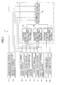
- Fig. 1 is a functional block diagram showing a road friction coefficients estimating apparatus according to an embodiment of the present invention;
- Fig. 2 is a diagram showing a two wheel vehicle model equivalent to a four wheel vehicle;
- Fig. 3 is a schematic diagram showing a table of engine torque versus engine speeds in respective throttle valve opening angles;
- Fig. 4 is schematic diagram showing a table of brake pressure versus brake pedal depressing effort;
- Fig. 5 is an explanatory view showing forces exerted on wheels;
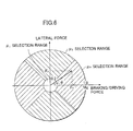
- Fig. 6 is an explanatory view showing an estimating value selection friction circle; and
- Fig. 7 is a flowchart showing a routine for selecting estimating value.
-
- Referring now to Fig. 1, reference numeral 1 denotes a road friction coefficient estimating apparatus to be installed on a vehicle. Reference numeral 2 denotes a control section of the road friction coefficient estimating apparatus 1. The control section 2 comprises a first road friction coefficient estimating section 5 as a first road friction coefficient estimating means for calculating a first road friction coefficient estimating value µy based on a vehicle motion in a lateral direction, a second road friction coefficient estimating section 6 as a second road friction coefficient estimating means for calculating a second road friction coefficient estimating value µx based on a vehicle motion in a longitudinal direction, a third road friction coefficient estimating section 7 as a third road friction coefficient estimating means for calculating a third road friction coefficient estimating value µi based on road surface conditions and an estimating value selection section 8 for selecting a most reliable value from among the road friction coefficients µx, µy, µi estimated in the first, second and third road friction coefficient estimating sections 5, 6 and 7 and outputting the value as a final road friction coefficient estimating value µ out.
- The first road friction coefficient estimating section 5 is connected with a front wheel steering angle sensor 10, a wheel speed sensor 11, a lateral acceleration sensor 12 and a yaw rate sensor 13 and inputs a front wheel steering angle δf, respective wheel speeds Vfl, Vfr, Vrl, Vrr, a lateral acceleration d2y/dt2, a yaw rate dψ/dt from respective sensors. In the first road friction coefficient estimating section 5, the first road friction coefficient estimating value µy is obtained by using the adaptive control theory which the applicant of the present invention discloses in Japanese Patent Application Laid-open No. 8-2274, that is, the first road friction coefficient estimating value µy is obtained based on the ratio of an equivalent cornering power of front wheels to that of rear wheels on an road surface having high friction coefficient according to the equation of vehicle motion in the lateral direction using a front wheel steering angle δf, a vehicle speed V, a lateral acceleration d2y/dt2, a yaw rate dψ/dt by extending the cornering powers of the front and rear wheels to a non-linear region. Specifically, the first road friction coefficient estimating value µy is calculated according the following adaptive control theory on the basis of the parameter adjustment rule.
- The equation of lateral transitional motion of a vehicle is expressed using a vehicle motion model illustrated in Fig. 2 as:
- On the other hand, the equation of rotational motion around gravity center of the vehicle is expressed as:
- The lateral acceleration (d2y/dt2) is expressed as:
- The cornering forces have a response similar to a first-order time lag. In this case, this time lag being neglected and letting the cornering forces be linearized introducing an idea of equivalent cornering power in which suspension characteristic is involved in tire characteristic, the cornering forces are expressed as follows:
- Using equivalent cornering powers taking the effect of roll and suspension of the vehicle into consideration, lateral slip angles βf, βr are can be simplified as follows:
- Various parameters are estimated by expressing the aforesaid equation of motion in state variables and applying the adaptive control theory to the equation according to the parameter adjustment rule . Next, cornering powers of the vehicle are obtained from the parameters thus estimated. There are many parameters for the vehicle such as vehicle mass, yaw inertia moment and the like. In the present invention, these parameters are assumed to be constant. Only cornering powers of tire are assumed to change. There are some reasons why the cornering powers of tire change, a non-linearity of lateral force versus slip angle, an effect of road friction coefficients, an effect of load transference and the like. The cornering powers Kf, Kr of front and rear wheels are obtained from the following equations:
- Accordingly, the cornering powers Kf, Kr of front and rear wheels are estimated according to the equations (8), (9) in an extended non-linear area.
- Further, road friction coefficient estimating values Ef, Er of front and rear wheels respectively are expressed as:
- As clearly understood from the above formulas, the method of thus estimating road friction coefficients based on vehicle behaviors in the lateral direction provides more accurate estimating values in case where a relatively large steering input is applied to the vehicle.
- The second road friction coefficient estimating section 6 is connected with the wheel speed sensors 11 for respective four wheels, an engine speed sensor 14 and a throttle valve opening angle sensor 15 and inputs wheel speeds Vrl, Vrr, engine speed Ne and throttle opening angle Tvo, respectively. In the second road friction coefficient estimating section 6, road friction coefficient estimating values µrl, µrr for left and right rear drive wheels respectively are calculated according to the method disclosed in Japanese Patent Application No. Toku-Hyo-Hei 3-500866 for example using wheel speeds Vrl, Vrr for left and right rear drive wheels respectively and engine torque Te and a second road friction coefficient estimating value µx is obtained from the road friction coefficient estimating values µrl, µrr. Engine torque Te is estimated from a table shown in Fig. 3 based on engine speed Ne and throttle valve opening angle Tvo.
- How to calculate the road friction coefficient estimating value µrl of the left rear left wheel is exemplified below.
- First, parameters for the rear left wheel P1l, P2l and Cl are estimated from the following formula.
- Based on thus obtained parameters, the road friction coefficient estimating value µrl is obtained by the following formulas:
- As clearly understood from the above formulas, the method of thus estimating road friction coefficients based on vehicle behaviors in the longitudinal direction provides more accurate estimating values in case where relatively large braking and driving forces are applied to the vehicle.
- The third road friction coefficient estimating section 7 is connected with a pair of left and right CCD cameras 16l, 16r and inputs mages of the scenery in front of the vehicle through these cameras. In the third friction coefficient estimating section 7, it is judged based on image data from the left and right CCD cameras whether or not the road on which the vehicle presently travels is in any situations of snowy, wet and dry conditions and the third road friction coefficient estimating value µi is obtained based on thus obtained road situation.
- That is, as the applicant of the present invention describes in detail in Japanese Patent Application Laid-open No. Toku-Gan-Hei 11-216191 for example, the judgment of snowy road in the third road friction coefficient estimating section 7 is made based on image data in a designated observing area in the images taken by the left and right CCD cameras 16l, 16r by detecting a road condition in which the road is regarded as to be covered with snow overall. Specifically, the number of brightness edges in the horizontal direction of the observing area and an overall size of brightness edges in the observing area are calculated respectively. In case where the number of brightness edges is smaller than a threshold value and further the overall size of brightness, it is judged that the road is regarded as a snowy road covered with snow overall.
- Further, the judgment of asphalted wet road in the third friction coefficient estimating section 7 is made by the method which the applicant of the present invention describes in Japanese Patent Application Unexamined No. Toku-Gan-Hei 11-216713. Specifically, first a distant data observing area is established in the frontal area of the vehicle where a road is supposed to exist and a hightwise distribution is evaluated with respect to the distance data existing in the observing area . That is , obtaining the height of the calculated distance data in a three dimensional space, the number of distance data of solid objects in the road surface is counted as the number of wet data. The asphalted wet road has a characteristic that many distance data are calculated below the road surface level. In consideration of this characteristic, in case where there are substantially many wet data in the distance data observing area, the road surface is judged to be in a wet condition.
- Further, in the third road friction coefficient estimating section 7, the road friction coefficient estimating value µi is established as follows:
on snowy road µi = 0.3
on asphalted wet road µi = 0.7
on asphalted dry road µi = 0.9 - The estimating value selection section 8 is connected with the front wheel steering angle sensor 10, the wheel speed sensor 11, the engine speed sensor 14, the throttle valve opening angle sensor 15, a gear position sensor 17 and a fluid pressure sensor 18 of a master cylinder and inputs front wheel steering angle δf, respective wheel speeds Vfl, Vfr, Vrl, Vrr, engine speed Ne, throttle valve opening angle Tvo, gear position Gp and fluid pressure Pmc of the master cylinder. Further, the estimating value selection section 8 is connected with the first, second and third road friction coefficient estimating section 5, 6 and 7 respectively and inputs the first, second and third road friction coefficient estimating values µy, µx and µi. Further, the estimating value selection section 8 calculates a longitudinal force (braking force and driving force) Fx exerted on the wheels and a lateral force Fy exerted on wheels based on the aforesaid sensor values and calculated estimating values and determines a final road friction coefficient estimating value µout based on these Fx, Fy.
- Below, processes of the estimating value selection section 8 will be described in detail by reference to a flowchart of an estimating value selection routine shown in Fig. 7.
- This routine is executed at a specified time interval. At a step S101, first braking and driving force Fx (=Ff + Fe) exerted on wheels is calculated, assuming that the road on which presently the vehicle travels has a reference road surface (flat road surface with road friction coefficient = 1).
- A total braking force Ff exerted on wheels is obtained by the following formula:
- Brake fluid pressures Pft, PRr are obtained from a table (see Fig. 4) stored in the estimating value selection section 8 based on master cylinder fluid pressure Pmc. In this case, front wheel brake fluid pressure PFt is established so as to coincide with master cylinder fluid pressure Pmc and rear wheel brake fluid pressure PRr is established so as to be reduced at a specified reduction pressure ratio from master cylinder fluid pressure Pmc.
- Driving force Fe exerted on the wheels is obtained by the following formula:
- The transmission output torque Tt is obtained from the following formula:
- The engine torque Te is obtained from a table (see Fig. 3) parameterizing engine speed Ne and throttle valve opening angle Tvo and the transmission gear ratio gr is determined based on a gear position Gp inputted.
- Next, at a step S102, lateral force Fy exerted on wheels is calculated, assuming that the road on which presently the vehicle travels has a reference road surface (flat road surface with road friction coefficient = 1). Specifically, at the step S102, a high friction coefficient (µ = 1) or reference road based lateral acceleration (d2y/dt2)H is estimated from an equation of state which will be described after and a lateral force Fy exerted on the wheels is calculated by multiplying the reference road based lateral acceleration (d2y/dt2)H by vehicle mass M.
- In this case, the reference road based lateral acceleration (d2y/dt2)H is calculated from the following equation of state which is described in detail in Japanese Patent Applicalion No. Toku-Gan-Hei 11-266216 filed by the applicant of the present invention.


- In the estimating value selection section 8, a reference road based slip angular velocity (dβ/dt)H and a refernce road based yaw angular acceleration (d2 ψ /dt2)H are obtained by calculating (dx(t)/dt) = [(dβ/dt) (d2ψ/dt2)]T in a vehicle operating condition (vehicle speed V, front wheel steering angle δf), when equivalent cornering powers Kf, Kr at 1.0 for example of road friction coefficient have been established beforehand in the formula (22). Then, a reference road based vehicle slip angle βH and a reference road based yaw rate (dψ/dt)H are obtained by integrating the vehicle slip angular velocity (d β/dt)H and the yaw angular acceleration (d2ψ/dt2)H. Further, a reference road based front wheel slip angle βfH is calculated by substituting the reference road based slip angle βH and yaw rate (dψ/dt)H into the aforesaid formula (6). Further, a reference road based lateral acceleration (d2y/dt2)H is calculated by substituting the reference road based vehicle slip angular velocity (dβ/dt)H and yaw rate (dψ/dt)H into the aforesaid formula (3).
- Next, at a step S103, as shown in Fig. 5, a resultant force Fall,ve of a braking/driving force Fx,ve and a lateral force Fy,ve is obtained by calculating a magnitude of the resultant force |Fall,ve| of the braking/driving force Fx,ve and the lateral force Fy,ve and an angle contained by the resultant force and x axis. Symbols having a subscript "ve" denote values expressed in vector.
- That is, the resultant force Fall,ve of the braking/driving force Fx,ve and the lateral force Fy,ve is obtained by the following formulas:
- Since friction coefficients between road surface and rubber obey the principle of Coulomb's friction, resultant horizontal forces (Fall,ve )exerted between respective wheels and road surface never exceed a product of friction coefficient µ and vertical load M·g (M: vehicle mass, g: gravitational acceleration). That is, the following relationship is formed:
- In the estimating value selection section 8, which road friction estimating values has a highest reliability of the first to third road friction coefficient estimating values µy, µx and µi is selected by investigating the condition of the resultant force Fall,ve exerted on wheels in a friction circle on the reference road surface (flat and road friction coefficient= 1) in the processes of the following steps S104 to S108. Specifically, as shown in Fig. 5, selection areas of respective road friction coefficient estimating values µy, µx and µi are established in a friction circle and a road friction coefficient estimating value is selected by investigating which area of those selected ones contains the resultant force Fall,ve .
- When the program goes from the step S103 to a step S104, first, it is investigated whether or not the magnitude of the absolute vale |Fall,ve| of the resultant force exerted on the wheel is larger than 0.2·M·g for example. That is, at the step S104, it is checked whether or not the vehicle indicates a behavior enough to estimate road friction coefficients from the vehicle behaviors in the lateral or longitudinal directions by investigating whether or not the absolute value |Fall,ve| of the resultant force exerted on wheels is larger than a specified ratio (0.2·M·g) of the largest value µ·M·g (=M·g when µ = 1) which the absolute value can take.
- Further, at the step S104, in case where the absolute value |Fall,ve| of the resultant force exerted on wheels is smaller than 0.2·M·g, the program goes to a step S105 where a final road friction coefficient estimating value µout is established to µ i based on the judgment that the vehicle behavior is not enough and the third road friction coefficient estimating value µi estimated from the road conditions is most reliable and after that leaves the routine.
- On the other hand, at the step S104, in case where the absolute value |Fall,ve| of the resultant force exerted on wheels is larger than 0.2·M·g, it is judged that either of the road friction coefficient estimating values µx, µy which have been estimated from the vehicle behaviors in the lateral or longitudinal directions has a higher reliability than the third road friction coefficient estimating value µi which has been estimated from the road surface conditions and the program goes to a step S106.
- At the step S106, it is checked whether or not the angle contained by the resultant force Fall,ve and X axis is 45 degrees < < 135 degrees or 225 degrees < < 315 degrees. That is, it is checked whether or not the direction of the resultant force Fall,ve is biased in the lateral direction.
- In case where at the step S106 the resultant force Fall,ve is 45 degrees < < 135 degrees or 225 degrees < < 315 degrees with respect to x axis, that is, in case where the direction of the resultant force Fall,ve is biased in the lateral direction, after a final road friction coefficient estimating value µout is established to µy based on the judgment that the first road friction coefficient estimating value µy estimated from the vehicle behavior in the lateral direction is most reliable, the program leaves the routine.
- On the other hand, in case where at the step S106 the resultant force Fall,ve is in a range other than 45 degrees < < 135 degrees or 225 degrees < < 315 degrees with respect to x axis, that is, in case where the direction of the resultant force Fall,ve is biased in the longitudinal direction, after a final road friction coefficient estimating value µout is established to µx based on the judgment that the second road friction coefficient estimating value µx estimated from the vehicle behavior in the longitudinal direction is most reliable, the program leaves the routine.
- According to the embodiment described above, since the road friction coefficient is estimated based on the road conditions in addition to the vehicle behavior and a most reliable one is selected as a final road friction coefficient estimating value from a plurality of these estimated road friction coefficient estimating values, road friction coefficients can be estimated accurately in a wide range. Particularly, since the estimation of road friction coefficient based on the vehicle behavior is performed in two ways, one is based on the vehicle behavior in the lateral direction and the other is based on the vehicle behavior in the longitudinal direction and a most reliable one is selected from these road friction coefficients in two ways as a final road friction coefficient, the estimation accuracy of the road friction coefficients can be enhanced.
- Further, a most reliable one is selected as a final road friction coefficient estimating value based on the resultant force exerted on the wheel accurately by a simple process.
- Specifically, according to the magnitude of the force exerted on the wheel, either the road friction coefficient estimating value based on the vehicle behaviors or the road friction coefficient estimating value based on the road surface conditions is selected. Further, according to the direction of the force exerted on the wheel, either the road friction coefficient estimating value based on the vehicle behavior in the lateral direction or the road friction coefficient estimating value based on the vehicle behavior in the longitudinal direction is selected. These selections enable to perform an accurate estimation of road friction coefficients.
- While the presently preferred embodiment of the present invention has been shown and described, it is to be understood that this disclosure is for the purpose of illustration and that various changes and modifications may be made without departing from the scope of the invention as set forth in the appended claims .
Claims (7)
- A road friction coefficients estimating apparatus for a vehicle for estimating friction coefficients of road surfaces on which said vehicle travels, characterized by comprising:a first road friction coefficient estimating means for calculating a first road friction coefficient based on a vehicle behavior in a lateral direction;a second road friction coefficient estimating means for calculating a second road friction coefficient based on a vehicle behavior in a longitudinal direction;a third road friction coefficient estimating means for calculating a third road friction coefficient based on road conditions; andan estimating value selection means for selecting either one of said first, second and third road friction coefficients as a final road friction coefficient estimating value.
- The road friction coefficient estimating apparatus according to claim 1, wherein said estimating value selection means selects a road friction coefficient based on a horizontal force exerted on wheels.
- The road friction coefficient estimating apparatus according to claim 1 or 2, wherein said estimating value selection means selects said third road friction coefficient as a final road friction coefficient estimating value when the magnitude of said force is smaller than a specified value.
- The road friction coefficient estimating apparatus according to claim 1 or 2, wherein said estimating value selection means selects said first road friction coefficient as a final road friction coefficient estimating value when the magnitude of said force is larger than a specified value and the direction of said force is biased in a lateral direction.
- The road friction coefficient estimating apparatus according to claim 1 or 2, wherein said estimating value selection means selects said second road friction coefficient as a final road friction coefficient estimating value when the magnitude of said force is larger than a specified value and the direction of said force is biased in a longitudinal direction.
- The road friction coefficient estimating apparatus according to claim 1, 2, 3, 4 or 5, wherein said third road friction coefficient estimating means detects road conditions from images taken by an imaging means.
- The road friction coefficient estimating apparatus according to claim 6, characterized in that said imaging means is a stereoscopic picture imaging means and said images are a pair of images taken by said imaging means.
Applications Claiming Priority (2)
| Application Number | Priority Date | Filing Date | Title |
|---|---|---|---|
| JP2000327488A JP3271963B1 (en) | 2000-10-26 | 2000-10-26 | Road surface friction coefficient estimation device for vehicles |
| JP2000327488 | 2000-10-26 |
Publications (2)
| Publication Number | Publication Date |
|---|---|
| EP1201521A1 true EP1201521A1 (en) | 2002-05-02 |
| EP1201521B1 EP1201521B1 (en) | 2003-06-25 |
Family
ID=18804494
Family Applications (1)
| Application Number | Title | Priority Date | Filing Date |
|---|---|---|---|
| EP01125310A Expired - Lifetime EP1201521B1 (en) | 2000-10-26 | 2001-10-25 | Road friction coefficients estimating apparatus for vehicle |
Country Status (4)
| Country | Link |
|---|---|
| US (1) | US6597980B2 (en) |
| EP (1) | EP1201521B1 (en) |
| JP (1) | JP3271963B1 (en) |
| DE (1) | DE60100399T2 (en) |
Cited By (9)
| Publication number | Priority date | Publication date | Assignee | Title |
|---|---|---|---|---|
| EP1510428A3 (en) * | 2003-08-26 | 2005-11-16 | Fuji Jukogyo Kabushiki Kaisha | Road surface frictional coefficient estimating apparatus |
| FR2918749A1 (en) * | 2007-07-12 | 2009-01-16 | Michelin Soc Tech | METHOD FOR EVALUATING THE TRANSVERSAL ADHESION OF A TIRE ON A SNORED SOIL |
| EP2218621A1 (en) * | 2009-02-16 | 2010-08-18 | Honda Motor Co., Ltd. | Road surface frictional coefficient estimating apparatus |
| EP2372340A1 (en) * | 2010-11-25 | 2011-10-05 | Centrum dopravniho vyzkumu, v.v.i. | Mobile measuring kit for determination of longitudinal friction coefficient of roadway surface |
| WO2014094766A1 (en) * | 2012-12-20 | 2014-06-26 | Continental Teves Ag & Co. Ohg | Method for determining a carriageway condition from environment sensor data |
| WO2014094767A1 (en) * | 2012-12-20 | 2014-06-26 | Continental Teves Ag & Co. Ohg | Estimation of the coefficient of friction from camera and wheel rotation speed data |
| US10147002B2 (en) | 2013-02-19 | 2018-12-04 | Conti Temic Microelectronic Gmbh | Method and apparatus for determining a road condition |
| US10289920B2 (en) | 2013-11-15 | 2019-05-14 | Continental Teves Ag & Co. Ohg | Method and device for determining a roadway state by means of a vehicle camera system |
| DE102018103214B4 (en) | 2017-02-27 | 2023-12-07 | GM Global Technology Operations LLC | METHODS AND SYSTEMS FOR PROACTIVE ESTIMATION OF ROAD SURFACE COEFFICIENT OF FRICTION |
Families Citing this family (43)
| Publication number | Priority date | Publication date | Assignee | Title |
|---|---|---|---|---|
| US20030093790A1 (en) * | 2000-03-28 | 2003-05-15 | Logan James D. | Audio and video program recording, editing and playback systems using metadata |
| JP3539722B2 (en) * | 2000-11-16 | 2004-07-07 | 富士重工業株式会社 | Road surface friction coefficient estimation device for vehicles |
| WO2003014693A1 (en) * | 2001-08-06 | 2003-02-20 | Societe De Technologie Michelin | Method for determining components of forces exerted on a tyre and the self-alignment torque |
| US6549842B1 (en) * | 2001-10-31 | 2003-04-15 | Delphi Technologies, Inc. | Method and apparatus for determining an individual wheel surface coefficient of adhesion |
| FR2835919A1 (en) * | 2002-02-08 | 2003-08-15 | Michelin Soc Tech | MEASUREMENT OF MAXIMUM ADHESION COEFFICIENT FROM KNOWLEDGE OF GENERATED EFFORTS AND SELF-ALIGNMENT TORQUE IN THE TIRE CONTACT AIR |
| FR2835918A1 (en) * | 2002-02-08 | 2003-08-15 | Michelin Soc Tech | MEASUREMENT OF MAXIMUM ADHESION COEFFICIENT FROM MEASUREMENT OF THE CIRCUMFERENTIAL EXTENSION IN A SIDE OF A TIRE |
| JP3939612B2 (en) * | 2002-08-12 | 2007-07-04 | 株式会社豊田中央研究所 | Road friction estimation device |
| WO2005004007A1 (en) * | 2002-09-18 | 2005-01-13 | Dmetrix, Inc. | Method for referencing image data |
| JP4165380B2 (en) * | 2003-01-31 | 2008-10-15 | 株式会社豊田中央研究所 | Vehicle control method and vehicle control apparatus |
| JP2005028887A (en) * | 2003-07-07 | 2005-02-03 | Fuji Heavy Ind Ltd | Road surface friction coefficient estimating apparatus and road surface friction coefficient estimating method |
| JP4777339B2 (en) * | 2004-04-09 | 2011-09-21 | ソシエテ ド テクノロジー ミシュラン | Tire with deformation sensor and method for evaluating tire deflection |
| US7797095B2 (en) | 2005-02-23 | 2010-09-14 | Aviation Safety Technologies, Llc | Method and device of calculating aircraft braking friction and other relating landing performance parameters based on the data received from aircraft's on board flight data management system |
| US8346455B2 (en) * | 2005-02-23 | 2013-01-01 | Zoltan Ivan Rado | Method and device for communicating true runway braking performance using data from the flight data management systems of landed aircraft |
| JP4742818B2 (en) * | 2005-11-07 | 2011-08-10 | 日産自動車株式会社 | Vehicle deceleration control device |
| US7415872B2 (en) * | 2006-10-09 | 2008-08-26 | Chrysler Llc | Method and code for determining characteristic of road surface beneath moving vehicle |
| FR2909065B1 (en) * | 2006-11-27 | 2009-07-10 | Peugeot Citroen Automobiles Sa | STEERING DEVICE FOR IMPROVING THE POWER OF A VEHICLE. |
| FR2909946B1 (en) * | 2006-12-13 | 2010-09-17 | Soc Tech Michelin | METHOD FOR ESTIMATING A GROUND BOND FAULT RISK OF A MOTOR VEHICLE |
| EP2118873A2 (en) | 2006-12-19 | 2009-11-18 | Engineered Arresting Systems Corporation | System and method for providing runway conditions to landing aircraft |
| JP5104175B2 (en) * | 2007-10-02 | 2012-12-19 | 株式会社ジェイテクト | Vehicle control device |
| DE102007053256B3 (en) * | 2007-11-08 | 2009-07-09 | Continental Automotive Gmbh | Method and device for determining a coefficient of friction |
| FI124059B (en) * | 2008-09-19 | 2014-02-28 | Aalto Korkeakoulusaeaetioe | Improvement in vehicle operating system |
| DE102009041566B4 (en) * | 2009-09-15 | 2022-01-20 | Continental Teves Ag & Co. Ohg | Procedure for classifying the road surface friction coefficient |
| FR2954503B1 (en) * | 2009-12-18 | 2014-08-22 | Paris Aeroport | IMPROVED DEVICE FOR MEASURING THE DEGREE OF SLIDING A SOIL |
| US9550480B2 (en) | 2011-10-21 | 2017-01-24 | Autoliv Nissin Brake Systems Japan Co., Ltd. | Vehicle brake hydraulic pressure control apparatus and road surface friction coefficient estimating device |
| DE102013211027B4 (en) * | 2013-06-13 | 2025-02-06 | Continental Autonomous Mobility Germany GmbH | Method and device for determining the condition of a road surface of a lane to be driven by a vehicle |
| US10272919B2 (en) * | 2014-10-09 | 2019-04-30 | Gm Global Technology Operations, Llc | Methods and systems for estimating road surface friction coefficient using self aligning torque |
| US10275662B1 (en) * | 2016-09-30 | 2019-04-30 | Zoox, Inc. | Estimating friction based on image data |
| DE102016221932A1 (en) * | 2016-11-09 | 2018-05-09 | Robert Bosch Gmbh | Method and device for operating a driver assistance system, driver assistance system |
| JP6572264B2 (en) * | 2017-06-28 | 2019-09-04 | 株式会社Subaru | Vehicle road friction coefficient estimation apparatus and vehicle road friction coefficient estimation method |
| US11541893B2 (en) * | 2017-09-26 | 2023-01-03 | Nira Dynamics Ab | Friction estimation |
| US11364915B2 (en) | 2017-12-07 | 2022-06-21 | Nissan Motor Co., Ltd. | Road condition determination method and road condition determination device |
| JP7135365B2 (en) * | 2018-03-23 | 2022-09-13 | 三菱自動車工業株式会社 | Vehicle driving support device |
| EP3546312B1 (en) * | 2018-03-26 | 2025-01-15 | Polestar Performance AB | Method and system for handling conditions of a road on which a vehicle travels |
| GB201819471D0 (en) * | 2018-11-29 | 2019-01-16 | Steine Ken Erik | Runway maintenance apparatus |
| US12097886B2 (en) | 2018-12-20 | 2024-09-24 | Mitsubishi Electric Corporation | Travel plan generation device and autonomous driving system |
| US11543343B2 (en) | 2019-09-05 | 2023-01-03 | Volvo Car Corporation | Road friction estimation |
| KR20210070014A (en) * | 2019-12-04 | 2021-06-14 | 현대자동차주식회사 | Apparatus for estimating friction coefficient of road surface and method thereof |
| US11318947B2 (en) | 2019-12-23 | 2022-05-03 | Volvo Car Corporation | Estimating surface friction coefficients using rear-wheel steering excitations |
| JP7530201B2 (en) * | 2020-04-06 | 2024-08-07 | 株式会社Subaru | Road surface friction coefficient estimation device and steering device |
| CN112660134B (en) * | 2020-12-25 | 2022-09-27 | 浙江吉利控股集团有限公司 | Road surface adhesion coefficient estimation method and device |
| US11772641B2 (en) * | 2021-05-26 | 2023-10-03 | GM Global Technology Operations LLC | Vehicle lateral motion management with preview road surface information |
| CN114506333B (en) * | 2022-02-23 | 2023-03-21 | 阿波罗智能技术(北京)有限公司 | Road adhesion coefficient determination method, device and equipment and automatic driving vehicle |
| CN117125052B (en) * | 2022-05-20 | 2025-11-04 | 比亚迪股份有限公司 | Methods for estimating road surface adhesion coefficient and methods and devices for torque control. |
Citations (6)
| Publication number | Priority date | Publication date | Assignee | Title |
|---|---|---|---|---|
| DE3735673A1 (en) * | 1987-10-22 | 1989-05-03 | Bosch Gmbh Robert | METHOD FOR CONTINUOUSLY DETERMINING THE FACTORY VALUE (MY) AND / OR SLOPE K (MY) OF THE (MY) SLIP CURVE |
| EP0412791A2 (en) * | 1989-08-10 | 1991-02-13 | LUCAS INDUSTRIES public limited company | Monitoring and predicting road vehicle/road surface conditions |
| JPH08156627A (en) * | 1994-12-08 | 1996-06-18 | Nissan Motor Co Ltd | Road friction coefficient state detector |
| US5742917A (en) * | 1994-06-27 | 1998-04-21 | Fuji Jukogyo Kabushiki Kaisha | Driving torque distribution control system for vehicle and the method thereof |
| JPH11147460A (en) * | 1997-11-17 | 1999-06-02 | Toyota Motor Corp | Road surface friction coefficient estimation device for vehicles |
| JP2000071968A (en) * | 1998-08-27 | 2000-03-07 | Fuji Heavy Ind Ltd | Road surface friction coefficient estimation device for vehicles |
Family Cites Families (7)
| Publication number | Priority date | Publication date | Assignee | Title |
|---|---|---|---|---|
| JP3393654B2 (en) * | 1991-12-25 | 2003-04-07 | マツダ株式会社 | Vehicle slip control device |
| JPH08258588A (en) * | 1995-03-27 | 1996-10-08 | Mazda Motor Corp | Road surface condition detection device in vehicle |
| JP3022798B2 (en) | 1997-02-27 | 2000-03-21 | 山形日本電気株式会社 | Spin coating equipment for semiconductor manufacturing |
| JP3382502B2 (en) * | 1997-05-20 | 2003-03-04 | 本田技研工業株式会社 | Automatic vehicle braking system |
| JP3485239B2 (en) * | 1997-09-10 | 2004-01-13 | 富士重工業株式会社 | Vehicle motion control device |
| JP2001043352A (en) | 1999-07-30 | 2001-02-16 | Fuji Heavy Ind Ltd | Outside monitoring device with fail-safe function |
| JP3349120B2 (en) * | 1999-09-09 | 2002-11-20 | 富士重工業株式会社 | Curve approach control device |
-
2000
- 2000-10-26 JP JP2000327488A patent/JP3271963B1/en not_active Expired - Fee Related
-
2001
- 2001-10-25 EP EP01125310A patent/EP1201521B1/en not_active Expired - Lifetime
- 2001-10-25 DE DE60100399T patent/DE60100399T2/en not_active Expired - Lifetime
- 2001-10-25 US US09/983,780 patent/US6597980B2/en not_active Expired - Lifetime
Patent Citations (6)
| Publication number | Priority date | Publication date | Assignee | Title |
|---|---|---|---|---|
| DE3735673A1 (en) * | 1987-10-22 | 1989-05-03 | Bosch Gmbh Robert | METHOD FOR CONTINUOUSLY DETERMINING THE FACTORY VALUE (MY) AND / OR SLOPE K (MY) OF THE (MY) SLIP CURVE |
| EP0412791A2 (en) * | 1989-08-10 | 1991-02-13 | LUCAS INDUSTRIES public limited company | Monitoring and predicting road vehicle/road surface conditions |
| US5742917A (en) * | 1994-06-27 | 1998-04-21 | Fuji Jukogyo Kabushiki Kaisha | Driving torque distribution control system for vehicle and the method thereof |
| JPH08156627A (en) * | 1994-12-08 | 1996-06-18 | Nissan Motor Co Ltd | Road friction coefficient state detector |
| JPH11147460A (en) * | 1997-11-17 | 1999-06-02 | Toyota Motor Corp | Road surface friction coefficient estimation device for vehicles |
| JP2000071968A (en) * | 1998-08-27 | 2000-03-07 | Fuji Heavy Ind Ltd | Road surface friction coefficient estimation device for vehicles |
Non-Patent Citations (3)
| Title |
|---|
| PATENT ABSTRACTS OF JAPAN vol. 1996, no. 10 31 October 1996 (1996-10-31) * |
| PATENT ABSTRACTS OF JAPAN vol. 1999, no. 11 30 September 1999 (1999-09-30) * |
| PATENT ABSTRACTS OF JAPAN vol. 2000, no. 06 22 September 2000 (2000-09-22) * |
Cited By (17)
| Publication number | Priority date | Publication date | Assignee | Title |
|---|---|---|---|---|
| US7234339B2 (en) | 2003-08-26 | 2007-06-26 | Fuji Jukogyo Kabushiki Kaisha | Road surface frictional coefficient estimating apparatus |
| EP1510428A3 (en) * | 2003-08-26 | 2005-11-16 | Fuji Jukogyo Kabushiki Kaisha | Road surface frictional coefficient estimating apparatus |
| US8342016B2 (en) | 2007-07-12 | 2013-01-01 | Michelin Recherche Et Technique S.A. | Method for evaluating the transversal grip of a tire on a snow covered ground |
| FR2918749A1 (en) * | 2007-07-12 | 2009-01-16 | Michelin Soc Tech | METHOD FOR EVALUATING THE TRANSVERSAL ADHESION OF A TIRE ON A SNORED SOIL |
| WO2009007523A3 (en) * | 2007-07-12 | 2009-03-19 | Michelin Soc Tech | Method for evaluating the transverse adhesion of a tyre on a snow-covered ground |
| EA015479B1 (en) * | 2007-07-12 | 2011-08-30 | Сосьете Де Текноложи Мишлен | Method for evaluating the transverse adhesion of a tyre on a snow-covered ground |
| CN101784875B (en) * | 2007-07-12 | 2013-01-16 | 米其林企业总公司 | Method for evaluating the transverse adhesion of a tyre on a snow-covered ground |
| EP2218621A1 (en) * | 2009-02-16 | 2010-08-18 | Honda Motor Co., Ltd. | Road surface frictional coefficient estimating apparatus |
| US8315758B2 (en) | 2009-02-16 | 2012-11-20 | Honda Motor Co., Ltd. | Road surface frictional coefficient estimating apparatus |
| EP2372340A1 (en) * | 2010-11-25 | 2011-10-05 | Centrum dopravniho vyzkumu, v.v.i. | Mobile measuring kit for determination of longitudinal friction coefficient of roadway surface |
| WO2014094766A1 (en) * | 2012-12-20 | 2014-06-26 | Continental Teves Ag & Co. Ohg | Method for determining a carriageway condition from environment sensor data |
| WO2014094767A1 (en) * | 2012-12-20 | 2014-06-26 | Continental Teves Ag & Co. Ohg | Estimation of the coefficient of friction from camera and wheel rotation speed data |
| US9643617B2 (en) | 2012-12-20 | 2017-05-09 | Continental Teves Ag & Co. Ohg | Friction coefficient estimation from camera and wheel speed data |
| US9676331B2 (en) | 2012-12-20 | 2017-06-13 | Continental Teves Ag & Co. Ohg | Method for determining a state of a pavement from surroundings sensor data |
| US10147002B2 (en) | 2013-02-19 | 2018-12-04 | Conti Temic Microelectronic Gmbh | Method and apparatus for determining a road condition |
| US10289920B2 (en) | 2013-11-15 | 2019-05-14 | Continental Teves Ag & Co. Ohg | Method and device for determining a roadway state by means of a vehicle camera system |
| DE102018103214B4 (en) | 2017-02-27 | 2023-12-07 | GM Global Technology Operations LLC | METHODS AND SYSTEMS FOR PROACTIVE ESTIMATION OF ROAD SURFACE COEFFICIENT OF FRICTION |
Also Published As
| Publication number | Publication date |
|---|---|
| JP3271963B1 (en) | 2002-04-08 |
| US20020072841A1 (en) | 2002-06-13 |
| US6597980B2 (en) | 2003-07-22 |
| DE60100399T2 (en) | 2004-02-05 |
| EP1201521B1 (en) | 2003-06-25 |
| DE60100399D1 (en) | 2003-07-31 |
| JP2002127882A (en) | 2002-05-09 |
Similar Documents
| Publication | Publication Date | Title |
|---|---|---|
| EP1201521B1 (en) | Road friction coefficients estimating apparatus for vehicle | |
| EP3578432B1 (en) | Method for estimating road surface friction coefficient of tire and device for estimating road surface friction coefficient of tire in high speed normal driving state | |
| US6650987B2 (en) | Road friction coefficients estimating apparatus for vehicle | |
| JP5096781B2 (en) | Vehicle road friction coefficient estimation device | |
| US7680577B2 (en) | Estimating method for road friction coefficient and vehicle slip angle estimating method | |
| US6526804B2 (en) | Road friction coefficient estimating apparatus for vehicle | |
| US20050096830A1 (en) | Integrated control apparatus for vehicle | |
| KR102923143B1 (en) | Apparatus and method for estimating the friction coefficient of road surface | |
| US20030074127A1 (en) | System for computing a road surface frictional coefficient | |
| EP3065967B1 (en) | Driveline and method of controlling a driveline | |
| JP4376549B2 (en) | Vehicle road friction coefficient estimation device | |
| EP1201522B1 (en) | Road friction coefficient estimating apparatus for vehicle | |
| US20050082911A1 (en) | Slip regulation algorithm for an automotive vehicle using a normal force estimate and a predetermined peak wheel slip value | |
| JP2007137138A (en) | Vehicle road friction coefficient estimation device | |
| JP3271956B2 (en) | Road surface friction coefficient estimation device for vehicles | |
| Johansson et al. | Tire/road friction estimation for front wheel driven vehicle | |
| JP4358070B2 (en) | Body slip angle estimation method | |
| JP7764953B2 (en) | Vehicle control device | |
| JP2010038194A (en) | Road surface friction coefficient estimating device | |
| JP2021181916A (en) | Road surface state estimation device |
Legal Events
| Date | Code | Title | Description |
|---|---|---|---|
| PUAI | Public reference made under article 153(3) epc to a published international application that has entered the european phase |
Free format text: ORIGINAL CODE: 0009012 |
|
| AK | Designated contracting states |
Kind code of ref document: A1 Designated state(s): AT BE CH CY DE DK ES FI FR GB GR IE IT LI LU MC NL PT SE TR Kind code of ref document: A1 Designated state(s): DE FR GB |
|
| AX | Request for extension of the european patent |
Free format text: AL;LT;LV;MK;RO;SI |
|
| 17P | Request for examination filed |
Effective date: 20020320 |
|
| GRAH | Despatch of communication of intention to grant a patent |
Free format text: ORIGINAL CODE: EPIDOS IGRA |
|
| AKX | Designation fees paid |
Free format text: DE FR GB |
|
| GRAH | Despatch of communication of intention to grant a patent |
Free format text: ORIGINAL CODE: EPIDOS IGRA |
|
| GRAA | (expected) grant |
Free format text: ORIGINAL CODE: 0009210 |
|
| AK | Designated contracting states |
Designated state(s): DE FR GB |
|
| REG | Reference to a national code |
Ref country code: GB Ref legal event code: FG4D |
|
| REG | Reference to a national code |
Ref country code: IE Ref legal event code: FG4D |
|
| REF | Corresponds to: |
Ref document number: 60100399 Country of ref document: DE Date of ref document: 20030731 Kind code of ref document: P |
|
| ET | Fr: translation filed | ||
| PLBE | No opposition filed within time limit |
Free format text: ORIGINAL CODE: 0009261 |
|
| STAA | Information on the status of an ep patent application or granted ep patent |
Free format text: STATUS: NO OPPOSITION FILED WITHIN TIME LIMIT |
|
| 26N | No opposition filed |
Effective date: 20040326 |
|
| REG | Reference to a national code |
Ref country code: IE Ref legal event code: MM4A |
|
| PGFP | Annual fee paid to national office [announced via postgrant information from national office to epo] |
Ref country code: FR Payment date: 20051010 Year of fee payment: 5 |
|
| GBPC | Gb: european patent ceased through non-payment of renewal fee |
Effective date: 20061025 |
|
| REG | Reference to a national code |
Ref country code: FR Ref legal event code: ST Effective date: 20070629 |
|
| PG25 | Lapsed in a contracting state [announced via postgrant information from national office to epo] |
Ref country code: GB Free format text: LAPSE BECAUSE OF NON-PAYMENT OF DUE FEES Effective date: 20061025 |
|
| PG25 | Lapsed in a contracting state [announced via postgrant information from national office to epo] |
Ref country code: FR Free format text: LAPSE BECAUSE OF NON-PAYMENT OF DUE FEES Effective date: 20061031 |
|
| PGFP | Annual fee paid to national office [announced via postgrant information from national office to epo] |
Ref country code: GB Payment date: 20051019 Year of fee payment: 5 |
|
| REG | Reference to a national code |
Ref country code: DE Ref legal event code: R082 Ref document number: 60100399 Country of ref document: DE Representative=s name: VOSSIUS & PARTNER PATENTANWAELTE RECHTSANWAELT, DE Ref country code: DE Ref legal event code: R081 Ref document number: 60100399 Country of ref document: DE Owner name: SUBARU CORPORATION, JP Free format text: FORMER OWNER: FUJI JUKOGYO K.K., TOKIO/TOKYO, JP |
|
| PGFP | Annual fee paid to national office [announced via postgrant information from national office to epo] |
Ref country code: DE Payment date: 20181019 Year of fee payment: 18 |
|
| REG | Reference to a national code |
Ref country code: DE Ref legal event code: R119 Ref document number: 60100399 Country of ref document: DE |
|
| PG25 | Lapsed in a contracting state [announced via postgrant information from national office to epo] |
Ref country code: DE Free format text: LAPSE BECAUSE OF NON-PAYMENT OF DUE FEES Effective date: 20200501 |