EP1201513A2 - Soft-start piston actuator - Google Patents
Soft-start piston actuator Download PDFInfo
- Publication number
- EP1201513A2 EP1201513A2 EP01309281A EP01309281A EP1201513A2 EP 1201513 A2 EP1201513 A2 EP 1201513A2 EP 01309281 A EP01309281 A EP 01309281A EP 01309281 A EP01309281 A EP 01309281A EP 1201513 A2 EP1201513 A2 EP 1201513A2
- Authority
- EP
- European Patent Office
- Prior art keywords
- passage
- actuator
- pressure surface
- pretensioner
- seatbelt
- Prior art date
- Legal status (The legal status is an assumption and is not a legal conclusion. Google has not performed a legal analysis and makes no representation as to the accuracy of the status listed.)
- Granted
Links
- 238000000034 method Methods 0.000 claims abstract description 9
- 239000000203 mixture Substances 0.000 claims abstract description 8
- 238000004804 winding Methods 0.000 claims abstract description 4
- 230000004913 activation Effects 0.000 claims description 13
- 238000004891 communication Methods 0.000 claims description 9
- 230000008878 coupling Effects 0.000 claims description 7
- 238000010168 coupling process Methods 0.000 claims description 7
- 238000005859 coupling reaction Methods 0.000 claims description 7
- 239000012530 fluid Substances 0.000 claims description 5
- 230000003213 activating effect Effects 0.000 claims description 3
- 230000002093 peripheral effect Effects 0.000 claims description 3
- 230000001939 inductive effect Effects 0.000 abstract 1
- 230000011664 signaling Effects 0.000 abstract 1
- 239000007789 gas Substances 0.000 description 38
- 239000003999 initiator Substances 0.000 description 9
- 230000007246 mechanism Effects 0.000 description 6
- 238000004519 manufacturing process Methods 0.000 description 5
- 239000000463 material Substances 0.000 description 4
- 230000001133 acceleration Effects 0.000 description 3
- 229910052751 metal Inorganic materials 0.000 description 3
- 239000002184 metal Substances 0.000 description 3
- 229910000831 Steel Inorganic materials 0.000 description 2
- 230000008901 benefit Effects 0.000 description 2
- 238000002485 combustion reaction Methods 0.000 description 2
- 239000004033 plastic Substances 0.000 description 2
- 229920003023 plastic Polymers 0.000 description 2
- 239000010959 steel Substances 0.000 description 2
- 241000180579 Arca Species 0.000 description 1
- 230000004075 alteration Effects 0.000 description 1
- 229910052782 aluminium Inorganic materials 0.000 description 1
- XAGFODPZIPBFFR-UHFFFAOYSA-N aluminium Chemical compound [Al] XAGFODPZIPBFFR-UHFFFAOYSA-N 0.000 description 1
- 230000000712 assembly Effects 0.000 description 1
- 238000000429 assembly Methods 0.000 description 1
- 230000015556 catabolic process Effects 0.000 description 1
- 239000000567 combustion gas Substances 0.000 description 1
- 230000006835 compression Effects 0.000 description 1
- 238000007906 compression Methods 0.000 description 1
- 238000006731 degradation reaction Methods 0.000 description 1
- 230000000694 effects Effects 0.000 description 1
- 238000007373 indentation Methods 0.000 description 1
- 230000000977 initiatory effect Effects 0.000 description 1
- 238000002347 injection Methods 0.000 description 1
- 239000007924 injection Substances 0.000 description 1
- 238000001746 injection moulding Methods 0.000 description 1
- 230000007257 malfunction Effects 0.000 description 1
- 229910001092 metal group alloy Inorganic materials 0.000 description 1
- 238000012986 modification Methods 0.000 description 1
- 230000004048 modification Effects 0.000 description 1
- 238000010008 shearing Methods 0.000 description 1
Images



Classifications
-
- F—MECHANICAL ENGINEERING; LIGHTING; HEATING; WEAPONS; BLASTING
- F15—FLUID-PRESSURE ACTUATORS; HYDRAULICS OR PNEUMATICS IN GENERAL
- F15B—SYSTEMS ACTING BY MEANS OF FLUIDS IN GENERAL; FLUID-PRESSURE ACTUATORS, e.g. SERVOMOTORS; DETAILS OF FLUID-PRESSURE SYSTEMS, NOT OTHERWISE PROVIDED FOR
- F15B15/00—Fluid-actuated devices for displacing a member from one position to another; Gearing associated therewith
- F15B15/20—Other details, e.g. assembly with regulating devices
- F15B15/22—Other details, e.g. assembly with regulating devices for accelerating or decelerating the stroke
- F15B15/221—Other details, e.g. assembly with regulating devices for accelerating or decelerating the stroke for accelerating the stroke, e.g. by area increase
-
- B—PERFORMING OPERATIONS; TRANSPORTING
- B60—VEHICLES IN GENERAL
- B60R—VEHICLES, VEHICLE FITTINGS, OR VEHICLE PARTS, NOT OTHERWISE PROVIDED FOR
- B60R22/00—Safety belts or body harnesses in vehicles
- B60R22/34—Belt retractors, e.g. reels
- B60R22/46—Reels with means to tension the belt in an emergency by forced winding up
- B60R22/4628—Reels with means to tension the belt in an emergency by forced winding up characterised by fluid actuators, e.g. pyrotechnic gas generators
- B60R22/4633—Linear actuators, e.g. comprising a piston moving along reel axis and rotating along its own axis
-
- F—MECHANICAL ENGINEERING; LIGHTING; HEATING; WEAPONS; BLASTING
- F15—FLUID-PRESSURE ACTUATORS; HYDRAULICS OR PNEUMATICS IN GENERAL
- F15B—SYSTEMS ACTING BY MEANS OF FLUIDS IN GENERAL; FLUID-PRESSURE ACTUATORS, e.g. SERVOMOTORS; DETAILS OF FLUID-PRESSURE SYSTEMS, NOT OTHERWISE PROVIDED FOR
- F15B15/00—Fluid-actuated devices for displacing a member from one position to another; Gearing associated therewith
- F15B15/19—Pyrotechnical actuators
-
- B—PERFORMING OPERATIONS; TRANSPORTING
- B60—VEHICLES IN GENERAL
- B60R—VEHICLES, VEHICLE FITTINGS, OR VEHICLE PARTS, NOT OTHERWISE PROVIDED FOR
- B60R22/00—Safety belts or body harnesses in vehicles
- B60R22/34—Belt retractors, e.g. reels
- B60R22/46—Reels with means to tension the belt in an emergency by forced winding up
- B60R22/4628—Reels with means to tension the belt in an emergency by forced winding up characterised by fluid actuators, e.g. pyrotechnic gas generators
- B60R2022/4642—Reels with means to tension the belt in an emergency by forced winding up characterised by fluid actuators, e.g. pyrotechnic gas generators the gas directly propelling a flexible driving means, e.g. a plurality of successive masses, in a tubular chamber
-
- B—PERFORMING OPERATIONS; TRANSPORTING
- B60—VEHICLES IN GENERAL
- B60R—VEHICLES, VEHICLE FITTINGS, OR VEHICLE PARTS, NOT OTHERWISE PROVIDED FOR
- B60R22/00—Safety belts or body harnesses in vehicles
- B60R22/34—Belt retractors, e.g. reels
- B60R22/46—Reels with means to tension the belt in an emergency by forced winding up
- B60R2022/468—Reels with means to tension the belt in an emergency by forced winding up characterised by clutching means between actuator and belt reel
Definitions
- the present invention relates in general to seatbelt pretensioners and, more particularly, to a pretensioner that incorporates a soft-start piston actuator.
- Seat belt pretensioners remove slack from a seat belt in the event of a collision in order to minimize forward movement of the passenger. While it is known to use pyrotechnic gas generators to operate mechanisms that wind up or otherwise pull in slack in the seat belt during a collision, such known pyrotechnic gas generators are often disposed internally of a seat belt retractor. Thus, the vehicle owner is faced with a significant cost penalty in that the entire pretensioner and retractor assembly must be replaced after activation because of the inability to prevent degradation of the retractor. High-temperature gases tend to abrade interior metal surfaces and produce ash and clinkers that bind up the retraction mechanism.
- the gas pressurization rate and the resultant initial driving force or acceleration of the piston can exceed the structural capability of the driven components. As a result, the entire assembly can malfunction due to fracturing of a given part.
- Another problem with known pretensioners is that they are designed to activate only in severe accidents, for example, accidents that exhibit inertial forces at least sufficient to activate the vehicle airbags.
- Safety system designers generally choose such a relatively high activation threshold due to the expense of replacing the entire seat belt retractor and pretensioner assembly after activation.
- seat belt pretensioners oftentimes may not protect passengers in less severe accidents.
- a related problem with known pretensioners is that when the pretensioner is activated only in severe accidents, activation will likely come relatively late in the crash sequence. Thus, the pretensioner must rapidly take up slack in the seat belt, sometimes injuring the passenger.
- U.S. Patent No. 5,967,440 herein incorporated by reference, describes a pretensioner and a conventional retractor for a safety belt system.
- the pretensioner is relatively complex and large, thus increasing the weight and spatial requirements of the seatbelt assembly.
- the present invention is directed to overcoming one or more of the problems or limitations associated with the prior art.
- a seatbelt pretensioner incorporates a soft-start piston actuator.
- the seatbelt pretensioner cooperates with a webbing reel shall axially disposed within a seatbelt retractor reel.
- the seatbelt pretensioner preferably includes a housing having a first passage in volumetric intersection with a second passage.
- the webbing reel shaft extends through the first passage.
- the second passage has a first end and a second end, the second end extending across arid past the diameter of the first passage.
- a clutch assembly is also provided, and as seen in a preferred embodiment, is fixed within the first passage.
- the webbing reel shaft extends through the clutch assembly.
- the seatbelt pretensioner is further equipped with a strap that has a first end fixed to the housing, a portion extending across a section of the second passage, and a second end coiled about and fixed to the clutch assembly. Still further, the seatbelt pretensioner provides a soft-start piston actuator with at least two pressure surfaces, wherein the actuator is positioned adjacent the first end of the second passage.
- a gas generant composition is also provided that is ignitable to supply pressurized gas that initially acts upon one of the at least two pressure surfaces with a resultant force great enough to drive the actuator a predetermined distance. As the actuator is propelled forward, the pressurized gas subsequently exerts a greater resultant force on at least one additional pressure surface. As the actuator is driven forward, it tensions the strap, thus resulting in a peripheral force about the clutch assembly. A simultaneous rotary advancement of the clutch assembly, the webbing reel shaft, and the webbing reel therefore tensions the attached seatbelt webbing.
- a method of pretensioning a seatbelt includes the steps of providing a housing with at least one passage, the passage having a first end and a second end, and providing a gas generator in fluid communication with the first end of the passage for providing a gas pressure thereto.
- the method also includes the steps of providing an actuator with at least a first and a second pressure surface, and positioning the actuator proximate the first end of the passage.
- the actuator and the passage are in flush communication at the first end.
- the method includes the steps of operably coupling the actuator to a seatbelt retractor webbing reel with a strap or cord, and activating the gas generator to initially provide a gas pressure to the first pressure surface.
- the gas pressure is supplied to the second pressure surface of the actuator, thereby driving the actuator from the first end toward the second end of the passage.
- Driving the actuator in this fashion tensions the strap and winds the seatbelt retractor webbing reel with a more gradual increase in velocity, thereby pretensioning the seatbelt webbing thereon.
- Pretensioner 10 in accordance with a preferred embodiment of the present invention.
- Pretensioner 10 may be used to pretension a seat belt (not shown) wound about a webbing reel of a conventional seat belt retractor mechanism.
- Pretensioning is generally defined as taking up slack in a seat belt in the event of sudden deceleration, or a collision.
- a webbing reel retractor shaft 12 extends from the retractor into pretensioner 10, and thereby cooperates with pretensioner 10 to tighten the seatbelt in the event of a sudden deceleration or an accident.
- the pretensioner 10 of the present invention has generic application to seatbelt retractors.
- Pretensioner 10 includes a housing 16 which is preferably a unitary block 16 formed from steel, aluminum, metal alloys, plastic and/or other known materials suitable for use in a pretensioner and for containment of the components described below.
- housing 16 is formed with a first passage 18 which volumetrically intersects a second passage 20.
- First passage 18 is preferably cylindrical and oriented perpendicular to second passage 20, which is preferably substantially coextensive with the length of housing 16.
- a webbing reel shaft 12 of a seatbelt retractor reel (not shown) extends through first passage 18, and also axially extends through a clutch assembly 30 which is fixed within first passage 18.
- Second passage or cylindrical bore 20 is preferably rectangular and has a first end 22, and a second end 24 that extends across and past the diameter of the first passage 18.
- a flexible strap 40 is provided having a first end 41 that is secured to housing 16, and a second end 42 coiled about and secured to clutch assembly 30.
- Strap 40 is preferably a metallic strip, but some other suitable flexible material such as a metal cord might be substituted.
- pretensioner 10 also provides an actuator or piston 50, positioned proximate the first end 22 of second passage 20.
- the actuator component(s) may be die cast, molded, or otherwise formed from metal, plastics, other suitably rigid materials, and combinations thereof.
- actuator 50 has a body portion 48 and an extension portion 49, both preferably cylindrical. Stated another way, actuator 50 preferably has an essentially cylindrical portion with a first diameter; and has a cylindrical protrusion 49 that has a smaller second diameter. Extension portion 49 and body portion 48 are preferably axially aligned. It should be appreciated that actuator 50 need not be cylindrical, and various deviations from the design of the disclosed embodiments might be made without departing from the scope of the present invention.
- actuator 50 might be flat-sided, or even rectangular in cross section. Actuator 50 might be constructed as a single piece or, alternatively, as a plurality of pieces or segments. Further, extension portion 49 need riot be axially aligned with body portion 48. In a preferred embodiment, extension portion 49 is insertable into a restriction portion 17 of housing 16 in a close clearance fashion.
- a first pressure surface 54 that is preferably circular, is located on extension portion 49.
- Piston 50 has a second pressure surface 56, that is located in part on body portion 48 and is preferably an annular surface circumferentially surrounding the base of extension 49. Second pressure surface 56 also includes a portion 54 located on extension portion 49.
- Second pressure surface 56 thus includes first pressure surface 54, by definition having a larger surface area than first pressure surface 54,
- first pressure surface 54 and second pressure surface 56 are circular and share a common centerpoint (not shown).
- a first annulus 55 and a second annulus 58 are preferably machined around the circumference of actuator 50 on extension portion 49 and body portion 48, respectively.
- a pair of flexible O-rings, 57 and 59, are preferably snap-fitted into annuli 55 and 58, thereby preventing the passage of gas through second passage 20 at their contact points.
- actuator piston 150 there is shown an alternative actuator piston 150.
- Piston 150 has a body portion 148 and an extension portion 149, each preferably cylindrical.
- piston 150 has a first pressure surface 154, and a second pressure surface 156 that includes first pressure surface 154.
- Piston 150 differs from piston 50, however, in that it includes a bore 153, that insertably receives a protrusion portion 117 of the housing 116.
- An O-ring 118 is preferably snap-fitted around protrusion portion 117 to form a gas-tight seal, while a second O-ring 119 is snap-fitted around extension portion 149.
- a gas generant composition 60 is provided and preferably placed adjacent first pressure surface 54, and within restriction portion 17.
- An initiator 62 is attached to housing 16, and abuts the first end 22 of second passage 20.
- initiator 62 is threadedly received by housing 16, although some other known suitable attachment method such as welds might be used.
- the illustrated position and orientation of initiator 62 might be varied without departing from the scope of the present invention, depending on space and manufacturing requirements. Further, initiator 62 need not be positioned within housing 16 at all.
- a set of contacts 64 can provide electrical current to initiator 62 to ignite gas generant 60 when activation of pretensioner 10 is desired.
- Gas generants useful in conjunction with the present invention are gas generants well known to those of ordinary skill in the art. For examples, see U.S. Patent Nos. 5,035,757, 5,460,668, 5,756,929, and 5,872,329, each herein incorporated by reference. These compositions exemplify, but do not limit, useful gas generant compositions.
- clutch assembly 30 is fixed about the retractor shaft 12, whereby the shaft 12 functions as an axis of rotation.
- clutch assembly 30 is fixed to a clip 31 with a perimeter roughly equivalent to that of first passage 18 and a key 33 corresponding to a fernale counterpart 33a in passage 18.
- Clip 31 is thus key-fitted within first passage 18, preventing rotation upon activation of clutch assembly 30.
- Clutch assembly 30 further includes first and second segments 32.
- a set of shear pins 34 are press-fitted through bores 35 through each segment 32.
- the shear pins 34 form slight protrusions 38 through the respective upper and lower surfaces of the segments 32. The protrusions 38 thus secure one end of each segment 32 to corresponding bores 31a in the clip 31.
- the protrusions 38 may be held in place by indentations (not shown) formed within a cover 39, or, another clip may be used to secure the segments 32 from the coiled energy of the strap 40 during normal vehicular operation.
- the retractor shaft 12 rotates freely of the segments 32 except when pretensioner 10 is activated.
- Figures 6-9 illustrate an alternative one-piece injection molding of a clutch assembly 30a.
- Clutch assembly 30a includes protrusions 38a integral to segments 32a, thereby securing the clutch assembly 30a to clip 31. Segments 32a are joined together by two spring members 43.
- clutch assembly is meant to apply generically to any clutch component or combination of components that are useful in the seatbelt retractor and pretensioner art.
- a clutch assembly is any component or combination of components that exert a rotatable and circumferential force about the retractor shaft 12 and thus produce a pretensioning or tightening of the belt by winding the associated webbing reel.
- U.S. Patent Nos. 5,743,480 and 5,222,994 illustrate known alternatives, and are herein incorporated by reference.
- a sensor (not shown) communicates electrical current via contacts 64 to initiator 62 in a conventional manner.
- the energizing of initiator 62 causes the combustion of gas generant composition 60 in restriction portion 17 of housing 16. Consequently, the gas pressure in restriction portion 60 begins to rise extremely rapidly, as does the pressure acting on first pressure surface 54.
- piston 50 begins to move through second channel 20 toward second end 24, pushing against strap 40 and activating clutch assembly 30, initiating rotation of reel shaft 12.
- O-ring 57 prevents any significant amount of combustion gas from prematurely escaping into second passage 20.
- pressurized gas can flow around extension portion 49 to exert force on second pressure surface 56, which includes the entire piston surface area exposed to gas pressure at first end 22 of second passage 20.
- O-ring 59 prevents any significant amount of gas from flowing past piston 50.
- piston 50's rate of travel through second passage 20 is initially relatively slow when pressure is acting only on the relatively lesser surface arca of first pressure surface 54, but becomes relatively fast once gas pressure can act on the relatively greater surface area of second pressure surface 56.
- the result is a relatively soft start, allowing the piston travel rate to be increased gradually, thus preventing damage to the various components that could hinder proper activation of pretensioner 10.
- piston 50 preferably travels to passage 20's second end 24 relatively rapidly, forcing a portion of strap 40 to second end 24 as illustrated in Figure 2.
- the relative sizes of the surface areas 54 and 56 may be varied to reconcile the acceleration of the actuator 50 with various design criteria of the pretensioner 10. Any number of different pressure surfaces might be incrementally employed during the pretensioner 10 activation, thereby facilitating enhanced control over the acceleration of the actuator 50, depending upon the application.
- strap 40 is preferably wrapped at least twice around the periphery of segments 32, and then hooked in place about an edge of either segment 32.
- actuator 50 propels the strap 40 to the second end 24 of passage 20
- strap 40 tightens about the clutch assembly 30, shearing pins 34, and exerting a peripheral force about clutch assembly 30.
- the forward motion of actuator 50 thus results in compression and constriction of the clutch segments 32 about the retractor axle 12.
- Rotary movement of clutch assembly 30 and webbing reel shaft 12 is thus effected as the associated teeth of segments 32 mate with the associated teeth of shaft 12.
- Clutch operation therefore results in rotation of webbing reel 12 of the retractor and tightening or pretensioning of the associated belt webbing.
- Cover 39 encloses the passages 18 and 20 and the components contained therein.
- Pretensioner 210 employing non-linear actuator travel and a multi-piece actuator.
- Pretensioner 210 includes a housing 216 with a first passage 218 and a second passage 220.
- Second passage 220 has a first end 222, and a second end 224.
- Second end 224 is preferably essentially arcuate shaped, and houses a clamping element 250 with a plurality of teeth 252 which secures one end of a flexible strap 240.
- Clamping element 250 is secured at one end by a pin 251, about which it can pivot within housing 216, leaving the opposite end of clamping element 250 free.
- clamping element 250 has an inside surface 254 which forms a part of an arcuate path traversed by the actuator 50.
- the remaining portion of the arcuate path is defined by housing 216, and includes the outer wall 219 of first passage 218, and the outer portion 231 of clutch assembly 230.
- Actuator 50 is preferably comprised of the piston 50 illustrated in Figures 1 and 2, and a plurality of bearing members 202, which are preferably cylindrical rotating elements, although some suitable alternative such as ball bearings might be used.
- piston 50 has a cylindrical extension 49, a body portion 48, and at least two pressure surfaces 54 and 56.
- An initiator 262 is provided, and can receive signals from a sensor via a set of contacts 264 to activate pretensioner 210 in a conventional manner. Initiator 262 may be attached in any suitable manner known in the art.
- a gas generant composition 260 similar to that used in a preferred embodiment is preferable.
- Actuator piston 50 is positioned adjacent the endmost bearing member 202.
- actuator piston 50 pushes against the endmost bearing member 202, which in turn serially communicates force to the adjacent members 202.
- bearing members 202 are freely rotatable, friction among the elements is minimized.
- bearing members 220 are forced ahead, traversing the arcuate path defined by the inner side 254 of clamping element 250, by outer wall 219, and by clutch/coupling assembly 230, driving strap 240 ahead.
- the use of multiple, rotatable bearing members thus allows the linear force from piston 50 to be converted into circumferential force about clutch/coupling assembly 230.
- clamping element 250 freely pivots about pin 251
- the driving force of bearing members 202 can force the teeth 252 of clamping element 250 against strap 240, ensuring it is held securely.
- the travel of actuator 50 about its arcuate path thus tensions strap 240 and winds reel 212 via the rotation of coupling assembly 230.
- a seatbelt pretensioner 310 has a housing 316 that includes a block portion 317 and a resilient cylindrical sleeve 315.
- Sleeve 315 has a first, closed, end 343, and a second, open, end 341, and includes a portion of a second passage 320.
- Sleeve 315 defines a restriction portion 318 similar to that in the previously disclosed embodiments.
- Housing 316 defines a first passage 318, within which a clutch assembly 330 is positioned about a rotatable reel 312.
- Second passage 320 is defined in part by block portion 317, and also in part by sleeve 315.
- An actuator 50 which is preferably a one-piece piston as in a preferred embodiment, is positioned within sleeve 315, and functions to tension a flexible strap 340 when driven through second passage 320.
- This embodiment of the present invention allows the invention to be constructed with alternative materials, and is lighter in weight than the aforementioned embodiments.
- the resilient cylindrical sleeve 315 is preferably a steel cylinder with relatively high structural integrity.
- the movement of the actuator and straps provide a multiplier effect similar to that provided by geared motion multipliers.
- the present invention simplifies the design and manufacturing of known motion multipliers and yet retains the multiplier advantage of reducing the strap or actuator stroke requirement.
- the substantially sealed housing minimizes the release of gas, noise, and flame.
- the use of at least two pressure surfaces on the piston actuator allows the piston to be accelerated gradually, minimizing the dangers and problems associated with the use of pyrotechnics to power the piston motion. Because the pretensioner is positioned remote from the seatbelt retractor mechanism, after activation of the pretensioner only the pretensioner need be replaced. In general, all or most of the retractor mechanism will be salvageable after pretensioner use.
- the invention can be characterized as a seatbelt pretensioner comprising, (1) a housing with at least one passage, the passage having a first end and a second end, and (2) a gas generator in fluid communication with the first end of the passage for providing a gas pressure thereto, wherein the pretensioner contains an actuator having at least a first and a second pressure surface such that each surface respectively occupies a plane substantially parallel to the other. The surfaces are oriented proximate the first end of the passage, and, the actuator and the passage are in flush communication at the first end.
- the gas generator Upon pretensioner activation, the gas generator initially provides a gas pressure to the first pressure surface, and then subsequently to the second pressure surface of the actuator thereby driving the actuator from the first end toward the second end of the passage, and thus winding a seatbelt retractor reel associated therewith. The seatbelt webbing of a seatbelt retractor is thereby pretensioned.
Landscapes
- Engineering & Computer Science (AREA)
- Mechanical Engineering (AREA)
- Physics & Mathematics (AREA)
- Fluid Mechanics (AREA)
- General Engineering & Computer Science (AREA)
- Chemical & Material Sciences (AREA)
- Analytical Chemistry (AREA)
- Automotive Seat Belt Assembly (AREA)
Abstract
Description
- The present invention relates in general to seatbelt pretensioners and, more particularly, to a pretensioner that incorporates a soft-start piston actuator.
- Seat belt pretensioners remove slack from a seat belt in the event of a collision in order to minimize forward movement of the passenger. While it is known to use pyrotechnic gas generators to operate mechanisms that wind up or otherwise pull in slack in the seat belt during a collision, such known pyrotechnic gas generators are often disposed internally of a seat belt retractor. Thus, the vehicle owner is faced with a significant cost penalty in that the entire pretensioner and retractor assembly must be replaced after activation because of the inability to prevent degradation of the retractor. High-temperature gases tend to abrade interior metal surfaces and produce ash and clinkers that bind up the retraction mechanism.
- Further, where pyrotechnic gas generators are used to supply the rapidly increasing gas pressure, the gas pressurization rate and the resultant initial driving force or acceleration of the piston can exceed the structural capability of the driven components. As a result, the entire assembly can malfunction due to fracturing of a given part.
- Another problem with known pretensioners is that they are designed to activate only in severe accidents, for example, accidents that exhibit inertial forces at least sufficient to activate the vehicle airbags. Safety system designers generally choose such a relatively high activation threshold due to the expense of replacing the entire seat belt retractor and pretensioner assembly after activation. As a result, seat belt pretensioners oftentimes may not protect passengers in less severe accidents. A related problem with known pretensioners is that when the pretensioner is activated only in severe accidents, activation will likely come relatively late in the crash sequence. Thus, the pretensioner must rapidly take up slack in the seat belt, sometimes injuring the passenger.
- U.S. Patent No. 5,967,440, herein incorporated by reference, describes a pretensioner and a conventional retractor for a safety belt system. The pretensioner is relatively complex and large, thus increasing the weight and spatial requirements of the seatbelt assembly.
- U.S. Patent No. 5,899,399, herein incorporated by reference, describes a state of the art pretensioner. The pretensioner is relatively complex, therefore complicating the manufacturing process.
- U.S. Patent No. 5,944,350, herein incorporated by reference, also describes a state of the art pretensioner. Again, the pretensioner is relatively large, thus increasing the weight and spatial requirements of the seatbelt assembly.
- The present invention is directed to overcoming one or more of the problems or limitations associated with the prior art.
- In one aspect of the invention, a seatbelt pretensioner incorporates a soft-start piston actuator. The seatbelt pretensioner cooperates with a webbing reel shall axially disposed within a seatbelt retractor reel. The seatbelt pretensioner preferably includes a housing having a first passage in volumetric intersection with a second passage. The webbing reel shaft extends through the first passage. The second passage has a first end and a second end, the second end extending across arid past the diameter of the first passage. A clutch assembly is also provided, and as seen in a preferred embodiment, is fixed within the first passage. The webbing reel shaft extends through the clutch assembly. The seatbelt pretensioner is further equipped with a strap that has a first end fixed to the housing, a portion extending across a section of the second passage, and a second end coiled about and fixed to the clutch assembly. Still further, the seatbelt pretensioner provides a soft-start piston actuator with at least two pressure surfaces, wherein the actuator is positioned adjacent the first end of the second passage. A gas generant composition is also provided that is ignitable to supply pressurized gas that initially acts upon one of the at least two pressure surfaces with a resultant force great enough to drive the actuator a predetermined distance. As the actuator is propelled forward, the pressurized gas subsequently exerts a greater resultant force on at least one additional pressure surface. As the actuator is driven forward, it tensions the strap, thus resulting in a peripheral force about the clutch assembly. A simultaneous rotary advancement of the clutch assembly, the webbing reel shaft, and the webbing reel therefore tensions the attached seatbelt webbing.
- In a second aspect, a method of pretensioning a seatbelt is provided. The pretensioning method includes the steps of providing a housing with at least one passage, the passage having a first end and a second end, and providing a gas generator in fluid communication with the first end of the passage for providing a gas pressure thereto. The method also includes the steps of providing an actuator with at least a first and a second pressure surface, and positioning the actuator proximate the first end of the passage. The actuator and the passage are in flush communication at the first end. Further, the method includes the steps of operably coupling the actuator to a seatbelt retractor webbing reel with a strap or cord, and activating the gas generator to initially provide a gas pressure to the first pressure surface. Subsequently, the gas pressure is supplied to the second pressure surface of the actuator, thereby driving the actuator from the first end toward the second end of the passage. Driving the actuator in this fashion tensions the strap and winds the seatbelt retractor webbing reel with a more gradual increase in velocity, thereby pretensioning the seatbelt webbing thereon. By first driving the actuator at a lesser velocity, then incrementally increasing the velocity, by increasing the surface area of the actuator acted upon by gas pressure, damage to the various system components is avoided.
-
- Figure 1 is a diagrammatic side view, partially in cross-section, of a seat belt pretensioner with a soft-start piston actuator, shown in its inactivated position;
- Figure 2 is a similar view of the embodiment from Figure 1, illustrating the soft-start piston actuator in its activated position;
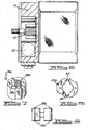
- Figure 3 is a partial side view of the soft-start piston actuator from Figure 1;
- Figure 4 is a partial side view of an alternative embodiment of the soft-start piston actuator;
- Figure 5 is a partial exploded view of the present invention;
- Figure 6 is a cross-sectional view of the pretensioner of Figure 1 taken along the line A-A;
- Figure 7 is a perspective view of a one-piece injection molded clutch assembly or coupling mechanism in accordance with the present invention;
- Figure 8 is a top view of the clutch assembly of Figure 7;
- Figure 9 is a side view of the clutch assembly of Figure 7;
- Figure 10 is a side view of an alternative embodiment of the present invention;
- Figure 11 is a side view of a second alternative embodiment of the present invention.
-
- Referring to Figure 1, there is shown a
pretensioner 10 in accordance with a preferred embodiment of the present invention.Pretensioner 10 may be used to pretension a seat belt (not shown) wound about a webbing reel of a conventional seat belt retractor mechanism. "Pretensioning" is generally defined as taking up slack in a seat belt in the event of sudden deceleration, or a collision. A webbingreel retractor shaft 12 extends from the retractor intopretensioner 10, and thereby cooperates withpretensioner 10 to tighten the seatbelt in the event of a sudden deceleration or an accident. Thepretensioner 10 of the present invention has generic application to seatbelt retractors. Examples of typical seat belt retractors to which the pretensioner of the present invention has application are taught in U.S. Patent Nos. 4,558,832 and 4,597,546. These examples are for illustrative purposes only and should not be construed to limit the scope of the present invention. The teachings of these patents, as well as those of all patents cited herein, are incorporated by reference. -
Pretensioner 10 includes ahousing 16 which is preferably aunitary block 16 formed from steel, aluminum, metal alloys, plastic and/or other known materials suitable for use in a pretensioner and for containment of the components described below. In a preferred embodiment,housing 16 is formed with afirst passage 18 which volumetrically intersects asecond passage 20.First passage 18 is preferably cylindrical and oriented perpendicular tosecond passage 20, which is preferably substantially coextensive with the length ofhousing 16. Awebbing reel shaft 12 of a seatbelt retractor reel (not shown) extends throughfirst passage 18, and also axially extends through aclutch assembly 30 which is fixed withinfirst passage 18. Second passage orcylindrical bore 20 is preferably rectangular and has afirst end 22, and asecond end 24 that extends across and past the diameter of thefirst passage 18. Aflexible strap 40 is provided having afirst end 41 that is secured tohousing 16, and asecond end 42 coiled about and secured toclutch assembly 30.Strap 40 is preferably a metallic strip, but some other suitable flexible material such as a metal cord might be substituted. - In accordance with the present invention, pretensioner 10 also provides an actuator or
piston 50, positioned proximate thefirst end 22 ofsecond passage 20. The actuator component(s) may be die cast, molded, or otherwise formed from metal, plastics, other suitably rigid materials, and combinations thereof. Referring now to Figure 3,actuator 50 has abody portion 48 and anextension portion 49, both preferably cylindrical. Stated another way, actuator 50 preferably has an essentially cylindrical portion with a first diameter; and has acylindrical protrusion 49 that has a smaller second diameter.Extension portion 49 andbody portion 48 are preferably axially aligned. It should be appreciated thatactuator 50 need not be cylindrical, and various deviations from the design of the disclosed embodiments might be made without departing from the scope of the present invention. For instance,actuator 50 might be flat-sided, or even rectangular in cross section.Actuator 50 might be constructed as a single piece or, alternatively, as a plurality of pieces or segments. Further,extension portion 49 need riot be axially aligned withbody portion 48. In a preferred embodiment,extension portion 49 is insertable into arestriction portion 17 ofhousing 16 in a close clearance fashion. Afirst pressure surface 54, that is preferably circular, is located onextension portion 49.Piston 50 has asecond pressure surface 56, that is located in part onbody portion 48 and is preferably an annular surface circumferentially surrounding the base ofextension 49.Second pressure surface 56 also includes aportion 54 located onextension portion 49.Second pressure surface 56 thus includesfirst pressure surface 54, by definition having a larger surface area thanfirst pressure surface 54, In a preferred embodiment,first pressure surface 54 andsecond pressure surface 56 are circular and share a common centerpoint (not shown). Afirst annulus 55 and asecond annulus 58 are preferably machined around the circumference ofactuator 50 onextension portion 49 andbody portion 48, respectively. A pair of flexible O-rings, 57 and 59, are preferably snap-fitted intoannuli second passage 20 at their contact points. Referring to Figure 4, there is shown analternative actuator piston 150.Piston 150 has a body portion 148 and anextension portion 149, each preferably cylindrical. Similar topiston 50,piston 150 has afirst pressure surface 154, and a second pressure surface 156 that includesfirst pressure surface 154.Piston 150 differs frompiston 50, however, in that it includes a bore 153, that insertably receives a protrusion portion 117 of the housing 116. An O-ring 118 is preferably snap-fitted around protrusion portion 117 to form a gas-tight seal, while a second O-ring 119 is snap-fitted aroundextension portion 149. - Returning to Figures 1 and 2, a
gas generant composition 60 is provided and preferably placed adjacentfirst pressure surface 54, and withinrestriction portion 17. Aninitiator 62 is attached tohousing 16, and abuts thefirst end 22 ofsecond passage 20. In Figures 1 and 2,initiator 62 is threadedly received byhousing 16, although some other known suitable attachment method such as welds might be used. The illustrated position and orientation ofinitiator 62 might be varied without departing from the scope of the present invention, depending on space and manufacturing requirements. Further,initiator 62 need not be positioned withinhousing 16 at all. A set ofcontacts 64 can provide electrical current to initiator 62 to ignitegas generant 60 when activation ofpretensioner 10 is desired. The supply of electrical current can be controlled by a sensor, for example an accelerometer, positioned elsewhere in the vehicle in a conventional manner. Gas generants useful in conjunction with the present invention are gas generants well known to those of ordinary skill in the art. For examples, see U.S. Patent Nos. 5,035,757, 5,460,668, 5,756,929, and 5,872,329, each herein incorporated by reference. These compositions exemplify, but do not limit, useful gas generant compositions. - Referring now to Figure 5,
clutch assembly 30 is fixed about theretractor shaft 12, whereby theshaft 12 functions as an axis of rotation. As illustrated,clutch assembly 30 is fixed to a clip 31 with a perimeter roughly equivalent to that offirst passage 18 and a key 33 corresponding to a fernale counterpart 33a inpassage 18. Clip 31 is thus key-fitted withinfirst passage 18, preventing rotation upon activation ofclutch assembly 30.Clutch assembly 30 further includes first and second segments 32. A set of shear pins 34 are press-fitted through bores 35 through each segment 32. The shear pins 34 formslight protrusions 38 through the respective upper and lower surfaces of the segments 32. Theprotrusions 38 thus secure one end of each segment 32 to corresponding bores 31a in the clip 31. At the other end of the segments 32, theprotrusions 38 may be held in place by indentations (not shown) formed within acover 39, or, another clip may be used to secure the segments 32 from the coiled energy of thestrap 40 during normal vehicular operation. When the segments 32 are fixed in place, theretractor shaft 12 rotates freely of the segments 32 except whenpretensioner 10 is activated. Figures 6-9 illustrate an alternative one-piece injection molding of a clutch assembly 30a. Clutch assembly 30a includesprotrusions 38a integral to segments 32a, thereby securing the clutch assembly 30a to clip 31. Segments 32a are joined together by two spring members 43. - In general, the clutch assemblies illustrated herein are merely exemplary of the many known clutches useful in the art Accordingly, as used herein, the term "clutch assembly" is meant to apply generically to any clutch component or combination of components that are useful in the seatbelt retractor and pretensioner art. Stated another way, a clutch assembly is any component or combination of components that exert a rotatable and circumferential force about the
retractor shaft 12 and thus produce a pretensioning or tightening of the belt by winding the associated webbing reel. U.S. Patent Nos. 5,743,480 and 5,222,994 illustrate known alternatives, and are herein incorporated by reference. - Returning now to Figures 1 and 2, when activation of
pretensioner 10 is desired, for example in the event of a crash, a sensor (not shown) communicates electrical current viacontacts 64 toinitiator 62 in a conventional manner. The energizing ofinitiator 62 causes the combustion ofgas generant composition 60 inrestriction portion 17 ofhousing 16. Consequently, the gas pressure inrestriction portion 60 begins to rise extremely rapidly, as does the pressure acting onfirst pressure surface 54. When a sufficient level of gas pressure is reached,piston 50 begins to move throughsecond channel 20 towardsecond end 24, pushing againststrap 40 and activatingclutch assembly 30, initiating rotation ofreel shaft 12. O-ring 57 prevents any significant amount of combustion gas from prematurely escaping intosecond passage 20. Whenpiston 50 has traveled a predetermined distance, pullingextension portion 49 out ofrestriction portion 17, pressurized gas can flow aroundextension portion 49 to exert force onsecond pressure surface 56, which includes the entire piston surface area exposed to gas pressure atfirst end 22 ofsecond passage 20. O-ring 59 prevents any significant amount of gas from flowingpast piston 50. Whenpiston 50 is in this position, withextension portion 49 freed fromrestriction portion 17, pressurized gas from the combustion ofgas generant 60 can act on,piston 50's total exposed surface area. Because the total force acting onpiston 50 is defined by the gas pressure and the exposed surface area, the resultant force onpiston 50 increases oncepiston 50 has traveled far enough to exposesecond pressure surface 56. As a result,piston 50's rate of travel throughsecond passage 20 is initially relatively slow when pressure is acting only on the relatively lesser surface arca offirst pressure surface 54, but becomes relatively fast once gas pressure can act on the relatively greater surface area ofsecond pressure surface 56. The result is a relatively soft start, allowing the piston travel rate to be increased gradually, thus preventing damage to the various components that could hinder proper activation ofpretensioner 10. - The embodiment of the present invention shown in Figure 4 functions in much the same manner, however, the different geometry illustrates how a varying design accomplishes the same goal without departing from the present invention's scope. Once
second pressure surface 56 is acted upon,piston 50 preferably travels topassage 20'ssecond end 24 relatively rapidly, forcing a portion ofstrap 40 tosecond end 24 as illustrated in Figure 2. Inmanufacturing pretensioner 10, the relative sizes of thesurface areas actuator 50 with various design criteria of thepretensioner 10. Any number of different pressure surfaces might be incrementally employed during thepretensioner 10 activation, thereby facilitating enhanced control over the acceleration of theactuator 50, depending upon the application. - Referring also to Figure 5,
strap 40 is preferably wrapped at least twice around the periphery of segments 32, and then hooked in place about an edge of either segment 32. As theactuator 50 propels thestrap 40 to thesecond end 24 ofpassage 20,strap 40 tightens about theclutch assembly 30, shearing pins 34, and exerting a peripheral force aboutclutch assembly 30. The forward motion ofactuator 50 thus results in compression and constriction of the clutch segments 32 about theretractor axle 12. Rotary movement ofclutch assembly 30 andwebbing reel shaft 12 is thus effected as the associated teeth of segments 32 mate with the associated teeth ofshaft 12. Clutch operation therefore results in rotation ofwebbing reel 12 of the retractor and tightening or pretensioning of the associated belt webbing.Cover 39 encloses thepassages - Referring to Figure 10, there is shown an alternative embodiment of the present invention, a
seatbelt pretensioner 210 employing non-linear actuator travel and a multi-piece actuator.Pretensioner 210 includes a housing 216 with afirst passage 218 and asecond passage 220.Second passage 220 has a first end 222, and asecond end 224.Second end 224 is preferably essentially arcuate shaped, and houses a clampingelement 250 with a plurality ofteeth 252 which secures one end of aflexible strap 240. Clampingelement 250 is secured at one end by apin 251, about which it can pivot within housing 216, leaving the opposite end of clampingelement 250 free. The other end ofstrap 240 is attached to a clutch/coupling assembly 230 that is fixed to a rotatable shaft 212, and housed withinfirst passage 218. Preferably, clampingelement 250 has aninside surface 254 which forms a part of an arcuate path traversed by theactuator 50. The remaining portion of the arcuate path is defined by housing 216, and includes the outer wall 219 offirst passage 218, and theouter portion 231 ofclutch assembly 230.Actuator 50 is preferably comprised of thepiston 50 illustrated in Figures 1 and 2, and a plurality of bearingmembers 202, which are preferably cylindrical rotating elements, although some suitable alternative such as ball bearings might be used. Similar to the aforementioned embodiments,piston 50 has acylindrical extension 49, abody portion 48, and at least twopressure surfaces initiator 262 is provided, and can receive signals from a sensor via a set ofcontacts 264 to activate pretensioner 210 in a conventional manner.Initiator 262 may be attached in any suitable manner known in the art. Agas generant composition 260 similar to that used in a preferred embodiment is preferable. -
Actuator piston 50 is positioned adjacent theendmost bearing member 202. Whenpretensioner 210 is activated by ignitinggas generant 260,actuator piston 50 pushes against theendmost bearing member 202, which in turn serially communicates force to theadjacent members 202. Because bearingmembers 202 are freely rotatable, friction among the elements is minimized. Aspiston 50 moves toward thesecond end 224 ofsecond passage 220, bearingmembers 220 are forced ahead, traversing the arcuate path defined by theinner side 254 of clampingelement 250, by outer wall 219, and by clutch/coupling assembly 230, drivingstrap 240 ahead. The use of multiple, rotatable bearing members thus allows the linear force frompiston 50 to be converted into circumferential force about clutch/coupling assembly 230. Because clampingelement 250 freely pivots aboutpin 251, the driving force of bearingmembers 202 can force theteeth 252 of clampingelement 250 againststrap 240, ensuring it is held securely. The travel ofactuator 50 about its arcuate path thus tensions strap 240 and winds reel 212 via the rotation ofcoupling assembly 230. - Referring to Figure 11, there is shown an additional alternative embodiment of the present invention wherein a
seatbelt pretensioner 310 has ahousing 316 that includes ablock portion 317 and a resilientcylindrical sleeve 315. Many of the features ofpretensioner 310 are similar to the features of the previously disclosed embodiments.Sleeve 315 has a first, closed,end 343, and a second, open,end 341, and includes a portion of asecond passage 320.Sleeve 315 defines arestriction portion 318 similar to that in the previously disclosed embodiments.Housing 316 defines afirst passage 318, within which a clutch assembly 330 is positioned about arotatable reel 312.Second passage 320 is defined in part byblock portion 317, and also in part bysleeve 315. Anactuator 50, which is preferably a one-piece piston as in a preferred embodiment, is positioned withinsleeve 315, and functions to tension aflexible strap 340 when driven throughsecond passage 320. This embodiment of the present invention allows the invention to be constructed with alternative materials, and is lighter in weight than the aforementioned embodiments. The resilientcylindrical sleeve 315 is preferably a steel cylinder with relatively high structural integrity. Each of the disclosed embodiments have different advantages, and will find application in different environments, depending on the particular manufacturing requirements as well as available mounting space and configuration in a vehicle. - Thus, in accordance with the presently disclosed embodiments of the present invention, the movement of the actuator and straps provide a multiplier effect similar to that provided by geared motion multipliers. The present invention, however, simplifies the design and manufacturing of known motion multipliers and yet retains the multiplier advantage of reducing the strap or actuator stroke requirement. The substantially sealed housing minimizes the release of gas, noise, and flame. The use of at least two pressure surfaces on the piston actuator allows the piston to be accelerated gradually, minimizing the dangers and problems associated with the use of pyrotechnics to power the piston motion. Because the pretensioner is positioned remote from the seatbelt retractor mechanism, after activation of the pretensioner only the pretensioner need be replaced. In general, all or most of the retractor mechanism will be salvageable after pretensioner use.
- In sum, the invention can be characterized as a seatbelt pretensioner comprising, (1) a housing with at least one passage, the passage having a first end and a second end, and (2) a gas generator in fluid communication with the first end of the passage for providing a gas pressure thereto, wherein the pretensioner contains an actuator having at least a first and a second pressure surface such that each surface respectively occupies a plane substantially parallel to the other. The surfaces are oriented proximate the first end of the passage, and, the actuator and the passage are in flush communication at the first end. Upon pretensioner activation, the gas generator initially provides a gas pressure to the first pressure surface, and then subsequently to the second pressure surface of the actuator thereby driving the actuator from the first end toward the second end of the passage, and thus winding a seatbelt retractor reel associated therewith. The seatbelt webbing of a seatbelt retractor is thereby pretensioned.
- It should be understood that the present description is for illustrative purposes only, and is not intended to limit the scope of the present invention in any way. Thus, those skilled in the art will recognize that various modifications and alterations to the presently disclosed embodiments could be made without departing from the spirit and scope of the present invention. Other aspects, features, and elements of the invention are evident upon examination of the figures and appended claims.
Claims (10)
- A seatbelt pretensioner for use with a seatbelt retractor reel, the pretensioner comprising:wherein upon pretensioner activation the gas generator initially provides a gas pressure to the first pressure surface, and then subsequently to the second pressure surface of said actuator thereby driving the actuator from the first end toward the second end of said passage.a housing with at least one passage, the passage having a first end and a second end;a gas generator in fluid communication with the first end of the passage for providing a gas pressure thereto;an actuator having at least a first and a second pressure surface, said surfaces oriented proximate the first end of said passage, and, said actuator and said passage in flush communication at said first end;
- The pretensioner of claim 1 wherein said actuator further comprises a piston having a body portion with at least one extension portion;
said first pressure surface is located on said extension portion and has a first surface area; and
said second pressure surface includes an annular portion located on said body portion that circumferentially encloses said extension, and also includes a circular portion located on said extension, said second pressure surface having a second surface area larger than said first surface area;
wherein said driving of the actuator from the first end toward the second end of the passage includes driving said actuator at a relatively lesser velocity, followed by driving said actuator at a relatively greater velocity. - The pretensioner of claim 1 or 2 wherein said extension portion is cylindrical, and is insertably received in a close-clearance fashion in a cylindrical restriction portion defined by said housing;
said gas generant composition is positioned adjacent said first pressure surface, and ignitable to release pressurized gas, which acts upon said first pressure surface to drive said piston a first distance at said lesser velocity, said pressurized gas then acting upon said second pressure surface to drive said piston a second distance at said greater velocity. - The pretensioner of claim 1, 2 or 3 wherein said actuator traverses an at least partially straight path that is substantially coextensive with the length of said housing
- The pretensioner of claim 1, 2 or 3 wherein said actuator traverses a partially arcuate path and said actuator comprises a piston piece and a plurality of bearing members, at least a portion of which are positioned in said passage.
- The pretensioner of any precably claim 4, wherein said housing further comprises a first passage volumetrically intersecting a perpendicular second passage;
a webbing reel shaft and a clutch assembly are fixed within said first passage, said webbing reel shaft extending axially through said clutch assembly;
a strap having a first end fixed to said housing, a portion extending across a section of said second passage, and a second end coiled about and fixed to said clutch assembly;
said driving of said actuator thereby effacting a tensioning of the strap and a peripheral force about the clutch assembly, and then a simultaneous rotary advancement of the clutch assembly, the webbing reel shaft, and the webbing reel, thus winding the reel and tensioning the seatbelt webbing thereon. - A method of pretensioning a seatbelt, comprising the steps of:providing a housing with at least one passage, the passage having a first end and a second end;providing a gas generator in fluid communication with the first end of the passage for providing a gas pressure thereto;providing an actuator, and positioning the actuator flush with the first end of the passage;operably coupling the actuator to a seatbelt retractor webbing reel;activating the gas generator to initially supply a first force to the actuator, then a second force to the actuator, thereby driving the actuator from the first end toward the second end of the passage, effecting a driving of the seatbelt retractor webbing reel, and tensioning seatbelt webbing thereon.
- The method of claim 7 wherein the step of providing an actuator further comprises providing a piston having a body portion with at least one extension portion;
locating a first pressure surface on the extension portion;
locating a second pressure surface in part on the body portion to circumferentially enclose the extension portion, and in part on the extension portion the second pressure surface being larger than the first pressure surface. - The method of claim 7 or 8 wherein the step of providing a gas generator further includes positioning a gas generant adjacent the first pressure surface, the generant being ignitable to supply pressurized gas, acting on the first pressure surface to drive the piston a first distance at a lesser velocity, then acting upon the second pressure surface to drive the piston a second distance at a greater velocity.
- In a seatbelt pretensioner comprising, (1) a housing with at least one passage, the passage having a first end and a second end, and (2) a gas generator in fluid communication with the first end of the passage for providing a gas pressure thereto, the improvement comprising:
an actuator having at least a first and a second pressure surface such that each surface respectively occupies a plane substantially parallel to the other, said surfaces oriented proximate the first end of said passage, and, said actuator and said passage in flush communication at said first end;
wherein upon pretensioner activation the gas generator initially provides a gas pressure to the first pressure surface, and then subsequently to the second pressure surface of said actuator thereby driving the actuator from the first end toward the second end of said passage.
Applications Claiming Priority (2)
| Application Number | Priority Date | Filing Date | Title |
|---|---|---|---|
| US24455400P | 2000-10-31 | 2000-10-31 | |
| US244554P | 2000-10-31 |
Publications (3)
| Publication Number | Publication Date |
|---|---|
| EP1201513A2 true EP1201513A2 (en) | 2002-05-02 |
| EP1201513A3 EP1201513A3 (en) | 2004-01-07 |
| EP1201513B1 EP1201513B1 (en) | 2005-12-07 |
Family
ID=22923232
Family Applications (1)
| Application Number | Title | Priority Date | Filing Date |
|---|---|---|---|
| EP01309281A Expired - Lifetime EP1201513B1 (en) | 2000-10-31 | 2001-10-31 | Soft-start piston actuator |
Country Status (4)
| Country | Link |
|---|---|
| US (1) | US6708914B2 (en) |
| EP (1) | EP1201513B1 (en) |
| JP (1) | JP2002264764A (en) |
| DE (1) | DE60115579T2 (en) |
Cited By (2)
| Publication number | Priority date | Publication date | Assignee | Title |
|---|---|---|---|---|
| WO2007012103A1 (en) * | 2005-07-27 | 2007-02-01 | Albert Kinzel | Device for tensioning safety belts |
| WO2014079587A1 (en) * | 2012-11-26 | 2014-05-30 | Trw Automotive Gmbh | Seat belt tensioner for a vehicle passenger restraint system |
Families Citing this family (13)
| Publication number | Priority date | Publication date | Assignee | Title |
|---|---|---|---|---|
| ATE370037T1 (en) * | 2002-08-03 | 2007-09-15 | Autoliv Dev | BELT RETRACTOR-BELT TENSIONER COMBINATION WITH TENSIONER DRIVE INTEGRATED INTO THE BELT SHAFT |
| EP1475283A1 (en) * | 2003-05-07 | 2004-11-10 | Hirschmann Automotive GmbH | Igniting Unit for a safety system of a vehicle |
| DE10327837A1 (en) * | 2003-06-20 | 2005-01-05 | Trw Occupant Restraint Systems Gmbh & Co. Kg | pretensioners |
| ATE382123T1 (en) * | 2005-07-15 | 2008-01-15 | Thomas Magnete Gmbh | PYROTECHNICAL RELEASE SYSTEM |
| WO2007062200A2 (en) * | 2005-11-25 | 2007-05-31 | Tk Holdings, Inc. | Gas generator |
| DE102006031845A1 (en) * | 2006-07-10 | 2008-01-17 | Trw Automotive Gmbh | Seat-belt tightener for safety belt system, has shaft supported in housing about rotational axis in rotatable manner, and tractive unit mounted in curve body and wound about peripheral surface of curve body before activating drive unit |
| DE102008025094B4 (en) * | 2008-05-26 | 2010-06-02 | Autoliv Development Ab | Belt tensioner with a metal band for power transmission |
| JP5366296B2 (en) * | 2008-12-29 | 2013-12-11 | テイ・エス テック株式会社 | VEHICLE SEAT AND ACTIVATION METHOD TO RESTRESS A SEATER OF A VEHICLE SEAT |
| DE102009017137A1 (en) * | 2009-04-15 | 2010-10-28 | Autoliv Development Ab | Belt pretensioner for belt rewinder of motor vehicle, has gas generator housing formed from two parts that are connected with each other, where one of parts forms piston after releasing connection of two parts |
| US8607703B2 (en) * | 2010-04-09 | 2013-12-17 | Bae Systems Information And Electronic Systems Integration Inc. | Enhanced reliability miniature piston actuator for an electronic thermal battery initiator |
| DE102011105697B4 (en) * | 2011-06-22 | 2015-02-12 | Autoliv Development Ab | Tensioner for a seat belt device |
| US8678440B1 (en) | 2012-12-20 | 2014-03-25 | Autoliv Asp, Inc. | Retractor-lap pretensioner with single micro-gas generator |
| CN109153369B (en) * | 2016-04-06 | 2021-05-07 | Trw汽车股份有限公司 | Actuator for releasing a force limiter of a belt retractor for a vehicle safety belt and belt retractor having such an actuator |
Citations (10)
| Publication number | Priority date | Publication date | Assignee | Title |
|---|---|---|---|---|
| US4558832A (en) | 1982-04-29 | 1985-12-17 | Bayern-Chemie Gesellschaft Fur Flugchemische Antriebe Mit Beschrankter Haftung | Take-up mechanism for safety belts |
| US4597546A (en) | 1982-11-29 | 1986-07-01 | Kabushiki Kaisha Takai-Rika-Denki-Seisakusho | Webbing retractor |
| US5035757A (en) | 1990-10-25 | 1991-07-30 | Automotive Systems Laboratory, Inc. | Azide-free gas generant composition with easily filterable combustion products |
| US5222994A (en) | 1991-03-12 | 1993-06-29 | Takata Corporation | Retractor shaft-rotating pretensioner |
| US5743480A (en) | 1995-02-01 | 1998-04-28 | Takata (Europe) Vehicle Safety Technology Gmbh | Safety belt arrangement in motor vehicles having a belt tensioner |
| US5756929A (en) | 1996-02-14 | 1998-05-26 | Automotive Systems Laboratory Inc. | Nonazide gas generating compositions |
| US5872329A (en) | 1996-11-08 | 1999-02-16 | Automotive Systems Laboratory, Inc. | Nonazide gas generant compositions |
| US5899399A (en) | 1997-06-12 | 1999-05-04 | Trw Vehicle Safety Systems Inc. | Seat belt pretensioner |
| US5944350A (en) | 1997-11-14 | 1999-08-31 | Takata Inc. | Buckle pretensioner |
| US5967440A (en) | 1996-08-13 | 1999-10-19 | Breed Automotive Technology, Inc. | Pretensioner for a seatbelt retractor |
Family Cites Families (26)
| Publication number | Priority date | Publication date | Assignee | Title |
|---|---|---|---|---|
| JPS5912910Y2 (en) * | 1978-08-25 | 1984-04-18 | 株式会社日本自動車部品総合研究所 | Backlash prevention device for seat belt tightening device |
| DE3231509C2 (en) | 1982-08-25 | 1985-04-18 | Daimler-Benz Ag, 7000 Stuttgart | Tensioning device for a belt end of a seat belt system that can be wound onto a belt roll |
| DE3635022A1 (en) * | 1985-10-26 | 1987-04-30 | Volkswagen Ag | TENSIONER FOR SAFETY BELTS |
| FR2604134B1 (en) | 1986-09-18 | 1988-12-23 | Peugeot Aciers Et Outillage | RETURN TENSIONER FOR SEAT BELT STRAP REEL, PARTICULARLY FOR MOTOR VEHICLE |
| DE3876081T2 (en) | 1987-12-23 | 1993-03-25 | Fuji Autolib Co Ltd | SAFETY BELT WITH TENSIONER. |
| JPH0624294A (en) | 1992-07-08 | 1994-02-01 | Takata Kk | Pretensioner for seat belt device |
| JPH0715458U (en) | 1993-08-30 | 1995-03-14 | 株式会社東海理化電機製作所 | Pretensioner |
| US5397075A (en) | 1993-09-10 | 1995-03-14 | Automotive Systems Laboratory, Inc. | Seat belt pretensioner |
| DE4415103A1 (en) | 1993-10-25 | 1995-04-27 | Trw Repa Gmbh | Belt tensioners for seat belt restraint systems in vehicles |
| US5881962A (en) * | 1994-04-11 | 1999-03-16 | Autoliv Development Ab | Mass-body drive for a rotary tightening device |
| US5553803A (en) | 1994-09-13 | 1996-09-10 | Takata Vehicle Safety Technology Gmbh | Belt tensioner for safety belts for motor vehicles |
| DE4432594A1 (en) | 1994-09-13 | 1996-03-14 | Takata Europ Gmbh | Vehicle seat belt tensioner |
| US5839686A (en) | 1995-10-12 | 1998-11-24 | Alliedsignal Inc. | Chain driven pretensioner and retractor |
| WO1997013660A1 (en) * | 1995-10-12 | 1997-04-17 | Alliedsignal Inc. | Spiral tube compact pretensioner and retractor |
| US5697571A (en) | 1996-05-17 | 1997-12-16 | Alliedsignal Inc. | Chain link rack pretensioner |
| US5853135A (en) | 1997-02-21 | 1998-12-29 | Alliedsignal Inc. | Chain link rack pretensioner |
| DE29710325U1 (en) | 1997-06-12 | 1998-10-15 | Trw Occupant Restraint Systems Gmbh, 73551 Alfdorf | Belt tensioners for an occupant restraint system |
| DE29717367U1 (en) * | 1997-09-29 | 1998-02-12 | Trw Occupant Restraint Systems Gmbh, 73551 Alfdorf | Pyrotechnic drive, in particular for vehicle occupant restraint systems |
| US6036274A (en) | 1997-11-13 | 2000-03-14 | Breed Automotive Technology, Inc. | Drive pulley, compact buckle pretensioner |
| GB2331275B (en) | 1997-11-18 | 2001-12-12 | Alliedsignal Sistemi Di Sicure | Clutch housing for a safety belt pretensioner |
| US5863009A (en) * | 1997-12-24 | 1999-01-26 | Trw Vehicle Safety Systems Inc. | Apparatus for pretensioning seat belt webbing |
| US5906328A (en) | 1998-03-12 | 1999-05-25 | Takata Corporation | Pre-tensioner for seat belt device |
| DE19846227A1 (en) * | 1998-10-07 | 2000-04-13 | Breed Automotive Tech | Piston drive for tightening a vehicle seat belt |
| DE10010379B4 (en) | 1999-03-04 | 2005-09-08 | Autoliv Development Ab | seat belt system |
| US6419177B2 (en) * | 2000-02-04 | 2002-07-16 | Automotive Systems Laboratory, Inc. | Seat belt pretensioner |
| US6340176B1 (en) * | 2000-03-31 | 2002-01-22 | Delphi Technologies, Inc. | Seat restraint tensioner |
-
2001
- 2001-10-31 EP EP01309281A patent/EP1201513B1/en not_active Expired - Lifetime
- 2001-10-31 US US10/000,723 patent/US6708914B2/en not_active Expired - Fee Related
- 2001-10-31 DE DE60115579T patent/DE60115579T2/en not_active Expired - Fee Related
- 2001-10-31 JP JP2001334896A patent/JP2002264764A/en not_active Ceased
Patent Citations (10)
| Publication number | Priority date | Publication date | Assignee | Title |
|---|---|---|---|---|
| US4558832A (en) | 1982-04-29 | 1985-12-17 | Bayern-Chemie Gesellschaft Fur Flugchemische Antriebe Mit Beschrankter Haftung | Take-up mechanism for safety belts |
| US4597546A (en) | 1982-11-29 | 1986-07-01 | Kabushiki Kaisha Takai-Rika-Denki-Seisakusho | Webbing retractor |
| US5035757A (en) | 1990-10-25 | 1991-07-30 | Automotive Systems Laboratory, Inc. | Azide-free gas generant composition with easily filterable combustion products |
| US5222994A (en) | 1991-03-12 | 1993-06-29 | Takata Corporation | Retractor shaft-rotating pretensioner |
| US5743480A (en) | 1995-02-01 | 1998-04-28 | Takata (Europe) Vehicle Safety Technology Gmbh | Safety belt arrangement in motor vehicles having a belt tensioner |
| US5756929A (en) | 1996-02-14 | 1998-05-26 | Automotive Systems Laboratory Inc. | Nonazide gas generating compositions |
| US5967440A (en) | 1996-08-13 | 1999-10-19 | Breed Automotive Technology, Inc. | Pretensioner for a seatbelt retractor |
| US5872329A (en) | 1996-11-08 | 1999-02-16 | Automotive Systems Laboratory, Inc. | Nonazide gas generant compositions |
| US5899399A (en) | 1997-06-12 | 1999-05-04 | Trw Vehicle Safety Systems Inc. | Seat belt pretensioner |
| US5944350A (en) | 1997-11-14 | 1999-08-31 | Takata Inc. | Buckle pretensioner |
Cited By (4)
| Publication number | Priority date | Publication date | Assignee | Title |
|---|---|---|---|---|
| WO2007012103A1 (en) * | 2005-07-27 | 2007-02-01 | Albert Kinzel | Device for tensioning safety belts |
| WO2014079587A1 (en) * | 2012-11-26 | 2014-05-30 | Trw Automotive Gmbh | Seat belt tensioner for a vehicle passenger restraint system |
| CN104812633A (en) * | 2012-11-26 | 2015-07-29 | Trw汽车股份有限公司 | Seat belt tensioner for vehicle passenger restraint system |
| CN104812633B (en) * | 2012-11-26 | 2018-12-18 | Trw汽车股份有限公司 | Seat belt tensioners for vehicle occupants - seat belt retraction systems |
Also Published As
| Publication number | Publication date |
|---|---|
| US20020109029A1 (en) | 2002-08-15 |
| US6708914B2 (en) | 2004-03-23 |
| EP1201513B1 (en) | 2005-12-07 |
| DE60115579D1 (en) | 2006-01-12 |
| JP2002264764A (en) | 2002-09-18 |
| DE60115579T2 (en) | 2006-08-17 |
| EP1201513A3 (en) | 2004-01-07 |
Similar Documents
| Publication | Publication Date | Title |
|---|---|---|
| US6419177B2 (en) | Seat belt pretensioner | |
| US6505790B2 (en) | Pretensioner device | |
| US6708914B2 (en) | Soft-start piston actuator | |
| EP2051882B1 (en) | Seat belt pretensioner | |
| US5397075A (en) | Seat belt pretensioner | |
| KR102615602B1 (en) | Seatbelt pretensioning retractor assembly | |
| US5839686A (en) | Chain driven pretensioner and retractor | |
| CN109311447A (en) | Seat belt pretensioner assembly | |
| US7350734B2 (en) | Seat belt pretensioner | |
| US4434953A (en) | Dual spool pretensioner | |
| US6460794B1 (en) | Pretensioner drive | |
| US6076856A (en) | Belt tension and energy absorbing apparatus | |
| EP0600689B1 (en) | Seat belt retractor with pre-tensioner | |
| US5489072A (en) | Seat belt retractor with pre-tensioner | |
| US6520443B2 (en) | Pretensioner drive | |
| JP3792649B2 (en) | Pretensioner drive device | |
| JP3749183B2 (en) | Pretensioner drive device | |
| EP1284917A1 (en) | Pretensioner drive | |
| WO2006044541A2 (en) | Seatbelt pretensioner |
Legal Events
| Date | Code | Title | Description |
|---|---|---|---|
| PUAI | Public reference made under article 153(3) epc to a published international application that has entered the european phase |
Free format text: ORIGINAL CODE: 0009012 |
|
| AK | Designated contracting states |
Kind code of ref document: A2 Designated state(s): AT BE CH CY DE DK ES FI FR GB GR IE IT LI LU MC NL PT SE TR |
|
| AX | Request for extension of the european patent |
Free format text: AL;LT;LV;MK;RO;SI |
|
| PUAL | Search report despatched |
Free format text: ORIGINAL CODE: 0009013 |
|
| AK | Designated contracting states |
Kind code of ref document: A3 Designated state(s): AT BE CH CY DE DK ES FI FR GB GR IE IT LI LU MC NL PT SE TR |
|
| AX | Request for extension of the european patent |
Extension state: AL LT LV MK RO SI |
|
| 17P | Request for examination filed |
Effective date: 20040329 |
|
| 17Q | First examination report despatched |
Effective date: 20040716 |
|
| AKX | Designation fees paid |
Designated state(s): DE GB |
|
| GRAP | Despatch of communication of intention to grant a patent |
Free format text: ORIGINAL CODE: EPIDOSNIGR1 |
|
| GRAS | Grant fee paid |
Free format text: ORIGINAL CODE: EPIDOSNIGR3 |
|
| GRAA | (expected) grant |
Free format text: ORIGINAL CODE: 0009210 |
|
| AK | Designated contracting states |
Kind code of ref document: B1 Designated state(s): DE GB |
|
| REG | Reference to a national code |
Ref country code: GB Ref legal event code: FG4D |
|
| REF | Corresponds to: |
Ref document number: 60115579 Country of ref document: DE Date of ref document: 20060112 Kind code of ref document: P |
|
| PLBE | No opposition filed within time limit |
Free format text: ORIGINAL CODE: 0009261 |
|
| STAA | Information on the status of an ep patent application or granted ep patent |
Free format text: STATUS: NO OPPOSITION FILED WITHIN TIME LIMIT |
|
| 26N | No opposition filed |
Effective date: 20060908 |
|
| PG25 | Lapsed in a contracting state [announced via postgrant information from national office to epo] |
Ref country code: DE Free format text: LAPSE BECAUSE OF NON-PAYMENT OF DUE FEES Effective date: 20070501 |
|
| GBPC | Gb: european patent ceased through non-payment of renewal fee |
Effective date: 20061031 |
|
| PG25 | Lapsed in a contracting state [announced via postgrant information from national office to epo] |
Ref country code: GB Free format text: LAPSE BECAUSE OF NON-PAYMENT OF DUE FEES Effective date: 20061031 |