EP1201464A2 - Pneumatic radial tires - Google Patents
Pneumatic radial tires Download PDFInfo
- Publication number
- EP1201464A2 EP1201464A2 EP01308841A EP01308841A EP1201464A2 EP 1201464 A2 EP1201464 A2 EP 1201464A2 EP 01308841 A EP01308841 A EP 01308841A EP 01308841 A EP01308841 A EP 01308841A EP 1201464 A2 EP1201464 A2 EP 1201464A2
- Authority
- EP
- European Patent Office
- Prior art keywords
- tire
- turn
- radial direction
- outer end
- main body
- Prior art date
- Legal status (The legal status is an assumption and is not a legal conclusion. Google has not performed a legal analysis and makes no representation as to the accuracy of the status listed.)
- Granted
Links
Images


Classifications
-
- B—PERFORMING OPERATIONS; TRANSPORTING
- B60—VEHICLES IN GENERAL
- B60C—VEHICLE TYRES; TYRE INFLATION; TYRE CHANGING; CONNECTING VALVES TO INFLATABLE ELASTIC BODIES IN GENERAL; DEVICES OR ARRANGEMENTS RELATED TO TYRES
- B60C15/00—Tyre beads, e.g. ply turn-up or overlap
- B60C15/0009—Tyre beads, e.g. ply turn-up or overlap features of the carcass terminal portion
- B60C15/0027—Tyre beads, e.g. ply turn-up or overlap features of the carcass terminal portion with low ply turn-up, i.e. folded around the bead core and terminating at the bead core
-
- B—PERFORMING OPERATIONS; TRANSPORTING
- B60—VEHICLES IN GENERAL
- B60C—VEHICLE TYRES; TYRE INFLATION; TYRE CHANGING; CONNECTING VALVES TO INFLATABLE ELASTIC BODIES IN GENERAL; DEVICES OR ARRANGEMENTS RELATED TO TYRES
- B60C15/00—Tyre beads, e.g. ply turn-up or overlap
- B60C15/06—Flipper strips, fillers, or chafing strips and reinforcing layers for the construction of the bead
-
- B—PERFORMING OPERATIONS; TRANSPORTING
- B60—VEHICLES IN GENERAL
- B60C—VEHICLE TYRES; TYRE INFLATION; TYRE CHANGING; CONNECTING VALVES TO INFLATABLE ELASTIC BODIES IN GENERAL; DEVICES OR ARRANGEMENTS RELATED TO TYRES
- B60C15/00—Tyre beads, e.g. ply turn-up or overlap
- B60C15/06—Flipper strips, fillers, or chafing strips and reinforcing layers for the construction of the bead
- B60C15/0603—Flipper strips, fillers, or chafing strips and reinforcing layers for the construction of the bead characterised by features of the bead filler or apex
- B60C15/0607—Flipper strips, fillers, or chafing strips and reinforcing layers for the construction of the bead characterised by features of the bead filler or apex comprising several parts, e.g. made of different rubbers
-
- Y—GENERAL TAGGING OF NEW TECHNOLOGICAL DEVELOPMENTS; GENERAL TAGGING OF CROSS-SECTIONAL TECHNOLOGIES SPANNING OVER SEVERAL SECTIONS OF THE IPC; TECHNICAL SUBJECTS COVERED BY FORMER USPC CROSS-REFERENCE ART COLLECTIONS [XRACs] AND DIGESTS
- Y10—TECHNICAL SUBJECTS COVERED BY FORMER USPC
- Y10T—TECHNICAL SUBJECTS COVERED BY FORMER US CLASSIFICATION
- Y10T152/00—Resilient tires and wheels
- Y10T152/10—Tires, resilient
- Y10T152/10495—Pneumatic tire or inner tube
- Y10T152/10819—Characterized by the structure of the bead portion of the tire
-
- Y—GENERAL TAGGING OF NEW TECHNOLOGICAL DEVELOPMENTS; GENERAL TAGGING OF CROSS-SECTIONAL TECHNOLOGIES SPANNING OVER SEVERAL SECTIONS OF THE IPC; TECHNICAL SUBJECTS COVERED BY FORMER USPC CROSS-REFERENCE ART COLLECTIONS [XRACs] AND DIGESTS
- Y10—TECHNICAL SUBJECTS COVERED BY FORMER USPC
- Y10T—TECHNICAL SUBJECTS COVERED BY FORMER US CLASSIFICATION
- Y10T152/00—Resilient tires and wheels
- Y10T152/10—Tires, resilient
- Y10T152/10495—Pneumatic tire or inner tube
- Y10T152/10819—Characterized by the structure of the bead portion of the tire
- Y10T152/10828—Chafer or sealing strips
-
- Y—GENERAL TAGGING OF NEW TECHNOLOGICAL DEVELOPMENTS; GENERAL TAGGING OF CROSS-SECTIONAL TECHNOLOGIES SPANNING OVER SEVERAL SECTIONS OF THE IPC; TECHNICAL SUBJECTS COVERED BY FORMER USPC CROSS-REFERENCE ART COLLECTIONS [XRACs] AND DIGESTS
- Y10—TECHNICAL SUBJECTS COVERED BY FORMER USPC
- Y10T—TECHNICAL SUBJECTS COVERED BY FORMER US CLASSIFICATION
- Y10T152/00—Resilient tires and wheels
- Y10T152/10—Tires, resilient
- Y10T152/10495—Pneumatic tire or inner tube
- Y10T152/10819—Characterized by the structure of the bead portion of the tire
- Y10T152/10837—Bead characterized by the radial extent of apex, flipper or chafer into tire sidewall
-
- Y—GENERAL TAGGING OF NEW TECHNOLOGICAL DEVELOPMENTS; GENERAL TAGGING OF CROSS-SECTIONAL TECHNOLOGIES SPANNING OVER SEVERAL SECTIONS OF THE IPC; TECHNICAL SUBJECTS COVERED BY FORMER USPC CROSS-REFERENCE ART COLLECTIONS [XRACs] AND DIGESTS
- Y10—TECHNICAL SUBJECTS COVERED BY FORMER USPC
- Y10T—TECHNICAL SUBJECTS COVERED BY FORMER US CLASSIFICATION
- Y10T152/00—Resilient tires and wheels
- Y10T152/10—Tires, resilient
- Y10T152/10495—Pneumatic tire or inner tube
- Y10T152/10819—Characterized by the structure of the bead portion of the tire
- Y10T152/10846—Bead characterized by the chemical composition and or physical properties of elastomers or the like
Definitions
- This invention relates to a pneumatic radial tire, and more particularly to a heavy duty radial tire having an aspect ratio of no more than 60% and largely improving the durability of the bead portion.
- JP-A-5-16618, JP-A-8-324214 and the like propose an improvement in the structure of a stiffener composed of a soft rubber stock and a hard rubber stock, and an improvement of a cushion rubber arranged at an outside of a turn-up portion of a carcass ply in the widthwise direction of the tire, whereby the improvement of the durability of the bead portion is realized.
- the deformation in the circumferential direction is caused at zones ranging from the bead portion to the sidewall portion located in correspondence to a stepping-in part and a kicking-out part of the tread portion in the ground contact face of the tire, respectively, whereby a shearing strain in the circumferential direction is created in the turn-up portion of the carcass ply.
- Such a shearing strain can be mitigated by selecting an arranging conformation of the hard rubber stock in the stiffener as disclosed in JP-A-8-225005, whereby the durability of the bead portion can be enhanced.
- the above problem is considered due to the fact that the shearing strain in the circumferential direction is increased in the vicinity of the turn-up end of the carcass ply because the length of a zone ranging from a portion of a maximum tire width to a buttress portion in the cross section, which effectively contributes to absorb the deformation in the circumferential direction of the tire, is decreased accompanied with the lowering of the aspect ratio of the tire, and also the absolute amount of deformation in the circumferential direction in the traction and braking or the shearing strain in the circumferential direction is increased under an advancement in performances of the vehicle and the tire, the increase of the tire size and the like.
- an object of the invention to provide a pneumatic radial tire largely improving the durability of the bead portion by decreasing the shearing strain in the circumferential direction in the vicinity of the turn-up portion of the carcass ply.
- a pneumatic radial tire having an aspect ratio of no more than 60% and comprising at least one carcass ply composed of a main body portion extending between a pair of bead cores each embedded in the respective bead portion and a turn-up portion wound outward around each bead core in a radial direction of the tire, a stiffener arranged between the main body portion and the turn-up portion on an outside of the bead core in the radial direction of the tire, extending outward in the radial direction of the tire, and made of a soft rubber stock and a hard rubber stock, and a reinforcing member extending at an outside of the turn-up portion in a widthwise direction of the tire through a cushion rubber, the improvement wherein when the tire is inflated under an air pressure corresponding to 10% of a maximum air pressure, a height of an outer end of the turn-up portion in the radial direction is no more than 0.33 times a section height of the carcass p
- section height of the carcass ply means a height when measuring along the radial direction of the tire between an innermost position of the carcass in the radial direction and an outermost position thereof.
- maximum air pressure used herein means an air pressure corresponding to a maximum load capacity defined in JATMA YEAR BOOK.
- maximum air pressure means an air pressure corresponding to a maximum load capacity defined in JATMA YEAR BOOK.
- the height of the outer end of the turn-up portion of the carcass ply in the radial direction is made no more than 0.33 times the section height of the carcass ply, whereby force suppressing the deformation of the tire through the rim flange is sufficiently applied to a portion located in the vicinity of the outer end of the turn-up portion in the radial direction under an action of the bead core at a state of mounting the tire onto the rim to advantageously decrease the deformation in the circumferential direction of the portion located in the vicinity of the outer end of the turn-up portion in the radial direction and hence the shearing strain in the circumferential direction, so that the separation of the outer end of the turn-up portion in the radial direction can effectively be prevented.
- the outer end of the turn-up portion in the radial direction is more than 0.33 times, the outer end of the turn-up portion can not sufficiently be subjected to the force suppressing the deformation of the tire through the rim flange.
- the ratio of the thickness between the main body portion and the reinforcing member to the thickness between the main body portion and the outer end of the turn-up portion in the radial direction is made 1.2-1.8, more preferably, 1.3-1.7, whereby the reinforcing member is arranged so as to sufficiently be distant outward from the outer end in the radial direction to the outer portion in the widthwise direction of the tire in which the torsion deformation at a ground contact area is large under loading to thereby largely improve the reinforcing effect by the reinforcing member, whereby the amount of deformation in the circumferential direction can advantageously be decreased.
- the reinforcing member more reinforces the bead portion to the deformation in the circumferential direction under the decrease of the absorption area thereof resulted from the lowering of the aspect ratio of the tire, so that the shearing strain in the circumferential direction in the vicinity of the outer end of the turn-up portion can effectively be decreased.
- the ratio is less than 1.2, it is difficult to sufficiently develop the reinforcing function through the reinforcing member, while when it exceeds 1.8, the quantity of heat generation in the cushion rubber between the turn-up portion and the reinforcing member is increased to prematurely promote the thermal deterioration due to the rise of temperature during the running and hence the durability is not totally improved.
- a wire chafer is arranged from the main body portion of the carcass ply to the turn-up portion thereof along the carcass ply and an outer end thereof in the radial direction along the main body portion is positioned outward from the outer end of the turn-up portion of the carcass ply in the radial direction.
- the deformation in the circumferential direction concentrates in a zone located in the vicinity of the outer end of the turn-up portion, and hence there is caused a problem that the increase of the shearing strain at the zone become unavoidable.
- the reinforcing member located at the outside of the turn-up portion in the widthwise direction of the tire is constituted with three or four nylon chafers, at least one of which chafers extends up to an inner portion of the bead core just beneath the bead core in the radial direction, and outer ends of these nylon chafers in the radial direction are positioned outward from the outer end of the turn-up portion in the radial direction.
- the reinforcing member arranged at a large deformation region is made of nylon cords and the cord itself is flexible, so that the concentration of strain at the end of the reinforcing member can be controlled as compared with a case using steel cords to avoid the separation failure at the end of the reinforcing member.
- the reinforcing member is comprised of three or four nylon chafers, so that the required reinforcing function can effectively be developed.
- the shearing strain in the circumferential direction produced in the vicinity of the ends of the nylon chafers can advantageously be dispersed.
- At least one nylon chafer is extended up to the inner portion of the bead core just beneath the bead core in the radial direction to spread the function of the bead core fixing the bead portion to the nylon chafer, whereby the shearing strain in the circumferential direction can forcedly be decreased.
- the number of the nylon chafers is not more than two, the required reinforcing function can not sufficiently be developed, while when it is five or more, rubber is early thermal-degraded by the heat generation accompanied with the increase of the thickness and it is difficult to expect the improvement of the durability of the bead portion.
- the stiffener is constituted with a hard rubber stock located inward in the radial direction of the tire and having a Shore-A hardness of no less than 70, and a soft rubber stock located outward in the radial direction of the tire and having a Shore-A hardness of no more than 65.
- the deformation bending deformation, deformation in the circumferential direction
- the lose of bead shape produced in a long-term use can be controlled by the hard rubber stock to improve the durability.
- the stiffener is preferable to be constituted with the soft rubber stock and the hard rubber stock.
- a hardness of the cushion rubber is no more than 58, preferably 32-58 as a Shore-A hardness.
- the cushion rubber acts as a layer of mitigating the shearing strain in the circumferential direction between the turn-up portion and the reinforcing member.
- the hardness exceeds 58, the action mitigating the strain based on the deformation of the cushion rubber itself is not sufficient.
- the hardness is less than 32, the amount of deformation of the cushion rubber in the circumferential direction is too large, so that there is caused a fear of creating not only the separation failure of the outer end of the turn-up portion in the radial direction from the cushion rubber but also the troubles in the cushion rubber.
- a thickness of the hard rubber stock on the normal line drawn from the outer end of the turn-up portion in the radial direction toward the outer surface of the main body portion is made no more than 0.5 times the thickness between the outer end of the turn-up portion in the radial direction and the main body portion.
- the difference of rigidity between the inside and the outside of the bead portion in the radial direction of the tire can advantageously be removed while effectively preventing the concentration of the compression strain to the inside of the turn-up end in the widthwise direction of the tire. That is, when the above thickness exceeds 0.5 times, there is caused a fear of separating the outer end of the turn-up portion due to the concentration of the compression strain in the zone located in the vicinity of the outer end.
- FIG. 1 is shown a cross section of a half portion of an embodiment of the tire according to the invention at a state of mounting onto a rim and inflating under an air pressure corresponding to 10% of a maximum air pressure
- FIG. 2 shows an enlarged view of a main portion of the tire shown in FIG. 1.
- numeral 1 is a tread portion
- numeral 2 a sidewall portion extending inward from each side end of the tread portion 1 in a radial direction of the tire
- numeral 3 a bead portion connecting to an inner end of the sidewall portion 2 in the radial direction of the tire.
- This tire has an aspect ratio of no more than 60%.
- a radial carcass 4 forming a skeleton structure of the tire and reinforcing each of the above portions 1, 2 and 3 of the tire is comprised of at least one carcass ply 5.
- the carcass ply 5 comprises a main body portion 5a toroidally extending between a pair of bead cores 6a each embedded in the respective bead portion 3 and a turn-up portion 5b wound outward around each of the bead cores 6 from an inside in the widthwise direction of the tire toward an outside therein.
- a stiffener 7 gradually tapering outward in the radial direction of the tire is arranged between the main body portion 5a and the turn-up portion 5b of the carcass ply 5 at an outer circumference of the bead core 6.
- the stiffener 7 is constituted with a hard rubber stock 7a located inward in the radial direction of the tire so as to thin inward in the widthwise direction of the tire and having preferably a Shore-A hardness of no less than 70, and a soft rubber stock 7b located outward in the radial direction of the tire and having preferably a Shore-A hardness of no more than 65.
- a reinforcing member 9 is extended at the outside of the turn-up portion 5b of the carcass ply 5 in the widthwise direction of the tire through a cushion rubber 8 having preferably a Shore-A hardness of no more than 58.
- the reinforcing member 9 is comprised of three or four nylon chafers, i.e. four nylon chafers 9a-9d in the illustrated embodiment.
- outer ends of these nylon chafers 9a-9d in the radial direction are positioned stepwise at the outside of the turn-up portion 5b.
- the outer end of the nylon chafer 9a in the radial direction contacting with the cushion rubber 8 is positioned at an outermost side in the radial direction.
- At least one of the nylon chafers i.e. the nylon chafer 9d located at the widthwise outermost side in the illustrated embodiment is extended up to a position of the inner portion of the bead core just beneath the bead core 6 in the radial direction to enhance a restraining force of the bead core 6 to the reinforcing member 9.
- a height h of the outer end of the turn-up portion 5b in the radial direction is made no more than 0.33 times a section height H of the carcass ply 5 to enhance a restraining force of a rim flange RF to the turn-up portion 5b, while a ratio (d2/d1) of a thickness d2 between the main body portion 5a and the reinforcing member 9 to a thickness d1 between the outer end 5c of the turn-up portion 5b in the radial direction and the main body portion 5a as measured on a normal line drawn from the outer end 5c of the turn-up portion 5b in the radial direction onto an outer surface of the main body portion 5a is made within a range of 1.2-1.8 to ensure a sufficient development of the reinforcing function through the reinforcing member 9 without the excessive heat generation of the cushion rubber 8.
- a thickness of the hard rubber stock 7a on the above normal line is further made no more than 0.5 times the thickness d1, and a wire chafer 10 is arranged from the main body portion 5a of the carcass ply 5 to the turn-up portion5b thereof along the carcass ply 5.
- An outer end 10a of the wire chafer 10 in the radial direction extending along the main body portion 5a is positioned outward from the outer end 5c of the turn-up portion 5b in the radial direction, while an outer end 10b of the wire chafer 10 in the radial direction extending along the turn-up portion 5b is positioned inward from the outer end 5c of the turn-up portion 5b in the radial direction.
- numeral 11 is a belt
- numeral 12 a belt reinforcing layer.
- the belt 11 is comprised of one or more belt layers containing cords each extending wavily in the circumferential direction
- the belt reinforcing layer 12 is comprised of two steel cord layers, cords of which layers being crossed with each other at a cord angle of 30-70° with respect to the circumference of the tread.
- the shearing strain in the circumferential direction at the zone located in the vicinity of the outer end 5c of the turn-up portion can advantageously be decreased to largely improve the durability of the bead portion as mentioned above.
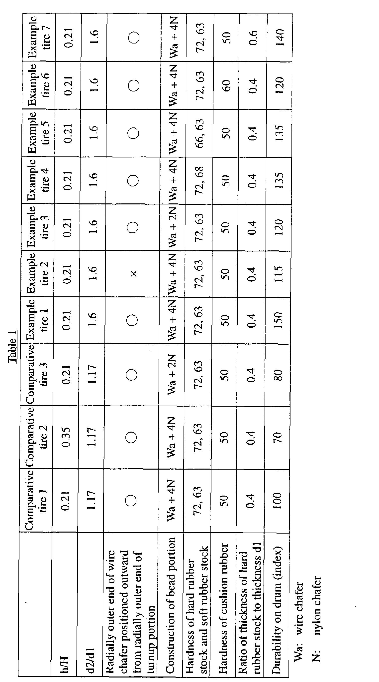
- Table 1 represents the ratio h/H of the height h of the outer end of the turn-up portion in the radial direction with respect to the section height H of the carcass ply and the ratio d2/d1 of a thickness d2 between the main body portion and the reinforcing member with respect to the thickness d1 between the outer end of the turn-up portion in the radial direction and the main body portion.
- the test for evaluating the durability of the bead portion is carried out to obtain results as shown in Table 1.
- the tire is mounted onto an approved rim of 9.00 ⁇ 22.5 under a maximum air pressure of 900 kPa and run on a drum testing machine having a radius of 1.7 m at a speed of 60 km/h under a load corresponding to 1.5 times a maximum load capacity of 3150 kg condition of the maximum inflation pressure of 900 kPa, the approved rim of 9.00 ⁇ 22.5 and weight corresponding to 1.5 times the maximum load capacity of 3150 kg until the breakage of the bead portion.
- the durability is represented by an index on the basis that comparative tire 1 is 100, wherein the larger the index value, the better the durability.
- the example tires can effectively improve the durability of the bead portion as compared with the comparative tires.
- the test for evaluating the durability on the drum is carried out by varying each of the thickness ratio (d2/d1) and the hardness of the cushion rubber as a parameter to obtain results as shown in graphs of FIGS. 4 and 5.
- the thickness ratio (d2/d1) is a range of 1.2-1.8, particularly 1.3-1.7, the excellent durability can be developed, and also when the hardness of the cushion rubber is no more than 58, particularly 32-58, the excellent durability can be developed.
- the durability of the bead portion can sufficiently be improved, and also even if the tire is repeatedly recapped, the excellent durability can be developed.
Landscapes
- Engineering & Computer Science (AREA)
- Mechanical Engineering (AREA)
- Tires In General (AREA)
Abstract
Description
Claims (6)
- A pneumatic radial tire having an aspect ratio of not more than 60% and comprising at least one carcass ply (5) composed of a main body portion (5a) extending between a pair of bead cores (6) each embedded in a respective bead portion (3) and a turn-up portion (5b) wound outward around each bead core in the radial direction of the tire, a stiffener (7) arranged between the main body portion (5a) and the turn-up portion (5b) on the outside of the bead core (6) in the radial direction of the tire, extending outward in the radial direction of the tire, and made of a soft rubber stock (7b) and a hard rubber stock (7a), and a reinforcing member (9) extending at an outside of the turn-up portion (5b) in the widthwise direction of the tire through a cushion rubber (8), characterized in that when the tire is inflated under an air pressure corresponding to 10% of a maximum air pressure, the height (h) of the outer end (5c) of the turn-up portion (5b) in the radial direction is not more than 0.33 times a section height (H) of the carcass ply (5), and a ratio of a thickness (d2) between the main body portion (5a) and the reinforcing member (9) to a thickness (d1) between the main body portion (5a) and the outer end (5c) of the turn-up portion (5b) in the radial direction as measured on a normal line drawn from the outer end (5c) of the turn-up portion (5b) in the radial direction onto an outer surface of the main body portion (5a) is within a range of 1.2-1.8.
- A pneumatic radial tire as claimed in claim 1, characterized in that a wire chafer (10) is arranged from the main body portion (5a) of the carcass ply (5) to the turn-up portion (5b) thereof along the carcass ply and an outer end (10a) thereof in the radial direction along the main body portion (5a) is positioned outward from the outer end (5c) of the turn-up portion (5b) of the carcass ply in the radial direction.
- A pneumatic radial tire as claimed in claim 1 or 2, characterized in that the reinforcing member (9) located at the outside of the turn-up portion (5b) in the widthwise direction of the tire is comprised of three or four nylon chafers (9a-9d), at least one of which chafers (9d) extends up to an inner portion of the bead core (6) just beneath the bead core in the radial direction, and the outer ends of said nylon chafers in the radial direction are positioned outward from the outer end (5c) of the turn-up portion (5b) in the radial direction.
- A pneumatic radial tire as claimed in any of claims 1 to 3, characterized in that the stiffener (7) is comprised of a hard rubber stock (7a) located inward in the radial direction of the tire and having a Shore-A hardness of not less than 70, and a soft rubber stock (7b) located outward in the radial direction of the tire and having a Shore-A hardness of not more than 65.
- A pneumatic radial tire as claimed in any of claims 1 to 4, characterized in that the cushion rubber (8) has a Shore-A hardness of not more than 58.
- A pneumatic radial tire as claimed in any of claims 1 to 5, characterized in that the thickness of the hard rubber stock (7a) on a normal line drawn from the outer end (5c) of the turn-up portion (5b) in the radial direction toward the outer surface of the main body portion (5a) is not more than 0.5 times the thickness (d1) between the outer end (5c) of the turn-up portion (5b) in the radial direction and the main body portion (5a).
Applications Claiming Priority (2)
| Application Number | Priority Date | Filing Date | Title |
|---|---|---|---|
| JP2000318954A JP2002120521A (en) | 2000-10-19 | 2000-10-19 | Pneumatic radial tire |
| JP2000318954 | 2000-10-19 |
Publications (3)
| Publication Number | Publication Date |
|---|---|
| EP1201464A2 true EP1201464A2 (en) | 2002-05-02 |
| EP1201464A3 EP1201464A3 (en) | 2003-03-26 |
| EP1201464B1 EP1201464B1 (en) | 2008-07-23 |
Family
ID=18797498
Family Applications (1)
| Application Number | Title | Priority Date | Filing Date |
|---|---|---|---|
| EP20010308841 Expired - Lifetime EP1201464B1 (en) | 2000-10-19 | 2001-10-18 | Pneumatic radial tires |
Country Status (5)
| Country | Link |
|---|---|
| US (1) | US6701988B2 (en) |
| EP (1) | EP1201464B1 (en) |
| JP (1) | JP2002120521A (en) |
| DE (1) | DE60134932D1 (en) |
| ES (1) | ES2309039T3 (en) |
Cited By (4)
| Publication number | Priority date | Publication date | Assignee | Title |
|---|---|---|---|---|
| EP1759892A3 (en) * | 2005-09-03 | 2008-07-02 | Continental Aktiengesellschaft | Pneumatic tyre for vehicles and method of manufacturing thereof |
| CN105939872A (en) * | 2014-03-06 | 2016-09-14 | 横滨橡胶株式会社 | Pneumatic tire |
| CN106029403A (en) * | 2014-02-20 | 2016-10-12 | 株式会社普利司通 | Pneumatic tire for agricultural machinery |
| CN107891710A (en) * | 2017-12-12 | 2018-04-10 | 江苏通用科技股份有限公司 | Half steel meridian small giant tire tyre bead of double-deck reinforcement and preparation method thereof |
Families Citing this family (14)
| Publication number | Priority date | Publication date | Assignee | Title |
|---|---|---|---|---|
| US7188655B2 (en) * | 2001-07-10 | 2007-03-13 | Bridgestone Corporation | Pneumatic tire |
| CN101516648B (en) * | 2006-09-22 | 2011-02-09 | 住友橡胶工业株式会社 | Radial tire for heavy load |
| JP4567763B2 (en) * | 2008-03-25 | 2010-10-20 | 住友ゴム工業株式会社 | Heavy duty tire |
| FR2953460B1 (en) * | 2009-12-09 | 2011-11-25 | Soc Tech Michelin | PNEUMATIC BOURRELET FOR HEAVY VEHICLE TYPE GENIE CIVIL |
| FR2961128B1 (en) * | 2010-06-15 | 2012-06-15 | Michelin Soc Tech | PNEUMATIC HAVING PERFECTED BOURRELETS. |
| CN103813912B (en) * | 2011-09-22 | 2015-11-25 | 横滨橡胶株式会社 | Air-inflation tyre |
| JP6398722B2 (en) * | 2012-11-30 | 2018-10-03 | 横浜ゴム株式会社 | Pneumatic tire |
| JP6276859B2 (en) * | 2013-12-13 | 2018-02-07 | ブリヂストン アメリカズ タイヤ オペレーションズ、 エルエルシー | Tire with electronic device in lower sidewall |
| JP6153858B2 (en) * | 2013-12-19 | 2017-06-28 | 東洋ゴム工業株式会社 | Pneumatic radial tire |
| JP5993402B2 (en) * | 2014-05-23 | 2016-09-14 | 住友ゴム工業株式会社 | Heavy duty tube tire |
| JP7172215B2 (en) | 2018-07-13 | 2022-11-16 | 住友ゴム工業株式会社 | Heavy duty pneumatic tire |
| JP7115226B2 (en) * | 2018-11-02 | 2022-08-09 | 横浜ゴム株式会社 | pneumatic tire |
| CN110171253B (en) * | 2019-05-29 | 2024-10-22 | 安徽佳通乘用子午线轮胎有限公司 | Reinforced tire bead structure with nylon wrapping edges and preparation method thereof |
| CN111993846B (en) * | 2020-08-24 | 2022-05-31 | 安徽佳通乘用子午线轮胎有限公司 | Small-size all-steel tire with high bearing performance |
Family Cites Families (13)
| Publication number | Priority date | Publication date | Assignee | Title |
|---|---|---|---|---|
| JP2530807B2 (en) * | 1985-06-13 | 1996-09-04 | 住友ゴム工業 株式会社 | Heavy-duty radial tire bead reinforcement structure |
| JPS632708A (en) * | 1986-06-24 | 1988-01-07 | Yokohama Rubber Co Ltd:The | Heavy-load pneumatic radial tire |
| JPH07110564B2 (en) * | 1986-10-27 | 1995-11-29 | 横浜ゴム株式会社 | Pneumatic radial tires |
| JP3059249B2 (en) | 1991-07-15 | 2000-07-04 | 株式会社ブリヂストン | Bead structure of pneumatic tire |
| JPH0664412A (en) * | 1991-08-30 | 1994-03-08 | Bridgestone Corp | Pneumatic radial tires for heavy loads |
| JPH06320922A (en) * | 1993-05-17 | 1994-11-22 | Ohtsu Tire & Rubber Co Ltd :The | Pneumatic radial tires |
| JPH06328914A (en) * | 1993-05-25 | 1994-11-29 | Ohtsu Tire & Rubber Co Ltd :The | Pneumatic radial tires |
| JPH07232520A (en) * | 1994-02-24 | 1995-09-05 | Ohtsu Tire & Rubber Co Ltd :The | Pneumatic radial tires |
| JP3105766B2 (en) | 1994-08-26 | 2000-11-06 | 株式会社ブリヂストン | Pneumatic radial tire |
| JP3583507B2 (en) * | 1995-05-30 | 2004-11-04 | 株式会社ブリヂストン | Pneumatic radial tire for heavy loads |
| JP3158058B2 (en) * | 1996-05-28 | 2001-04-23 | 住友ゴム工業株式会社 | Radial tires for heavy loads |
| JP3646199B2 (en) * | 1996-11-19 | 2005-05-11 | 東洋ゴム工業株式会社 | Heavy duty pneumatic radial tire |
| JP4242960B2 (en) * | 1998-12-24 | 2009-03-25 | 株式会社ブリヂストン | Heavy duty pneumatic radial tire |
-
2000
- 2000-10-19 JP JP2000318954A patent/JP2002120521A/en active Pending
-
2001
- 2001-10-18 DE DE60134932T patent/DE60134932D1/en not_active Expired - Lifetime
- 2001-10-18 EP EP20010308841 patent/EP1201464B1/en not_active Expired - Lifetime
- 2001-10-18 ES ES01308841T patent/ES2309039T3/en not_active Expired - Lifetime
- 2001-10-19 US US09/981,741 patent/US6701988B2/en not_active Expired - Lifetime
Cited By (8)
| Publication number | Priority date | Publication date | Assignee | Title |
|---|---|---|---|---|
| EP1759892A3 (en) * | 2005-09-03 | 2008-07-02 | Continental Aktiengesellschaft | Pneumatic tyre for vehicles and method of manufacturing thereof |
| CN106029403A (en) * | 2014-02-20 | 2016-10-12 | 株式会社普利司通 | Pneumatic tire for agricultural machinery |
| CN106029403B (en) * | 2014-02-20 | 2017-10-27 | 株式会社普利司通 | Pneumatic tires for agricultural machinery |
| US10661609B2 (en) | 2014-02-20 | 2020-05-26 | Bridgestone Corporation | Agricultural machinery pneumatic tire |
| CN105939872A (en) * | 2014-03-06 | 2016-09-14 | 横滨橡胶株式会社 | Pneumatic tire |
| EP3103658A4 (en) * | 2014-03-06 | 2017-10-18 | The Yokohama Rubber Company, Limited | Pneumatic tire |
| US10857843B2 (en) | 2014-03-06 | 2020-12-08 | The Yokohama Rubber Co., Ltd. | Pneumatic tire |
| CN107891710A (en) * | 2017-12-12 | 2018-04-10 | 江苏通用科技股份有限公司 | Half steel meridian small giant tire tyre bead of double-deck reinforcement and preparation method thereof |
Also Published As
| Publication number | Publication date |
|---|---|
| US20020153080A1 (en) | 2002-10-24 |
| EP1201464B1 (en) | 2008-07-23 |
| DE60134932D1 (en) | 2008-09-04 |
| JP2002120521A (en) | 2002-04-23 |
| EP1201464A3 (en) | 2003-03-26 |
| US6701988B2 (en) | 2004-03-09 |
| ES2309039T3 (en) | 2008-12-16 |
Similar Documents
| Publication | Publication Date | Title |
|---|---|---|
| US7017635B2 (en) | Tire with outside-in ply construction | |
| US6701988B2 (en) | Pneumatic radial tires | |
| US6237661B1 (en) | Run-flat tire with specified profile | |
| JP4621091B2 (en) | Pneumatic tire | |
| EP0314445B1 (en) | Safety tyre | |
| US20080006359A1 (en) | Runflat tire | |
| EP0958946B1 (en) | Heavy duty radial tyre | |
| JPWO2009078425A1 (en) | Pneumatic tire | |
| JP4107961B2 (en) | Pneumatic safety tire | |
| EP1129870B1 (en) | Pneumatic tires | |
| EP0689949B1 (en) | Pneumatical radial tires | |
| CN100396505C (en) | heavy duty tire | |
| EP0884200A2 (en) | Heavy duty pneumatic radial tyres | |
| EP0983875A2 (en) | Pneumatic tyre | |
| EP1116605B1 (en) | Pneumatic tire, having improved bead portion durability | |
| EP0698513B1 (en) | Pneumatic radial tires | |
| US12077021B2 (en) | Pneumatic tire | |
| EP0810105A1 (en) | Pneumatic radial tires provided with a side portion reinforcing layer | |
| EP0393965B1 (en) | Pneumatic radial tires having improved running performances | |
| JP4263934B2 (en) | Pneumatic tire | |
| EP0661180A1 (en) | Passenger radial tyre | |
| JP2003335110A (en) | Heavy duty pneumatic tires | |
| JP6501600B2 (en) | Pneumatic tire | |
| JP4816014B2 (en) | Pneumatic tire | |
| JP3064265B2 (en) | Pneumatic tire |
Legal Events
| Date | Code | Title | Description |
|---|---|---|---|
| PUAI | Public reference made under article 153(3) epc to a published international application that has entered the european phase |
Free format text: ORIGINAL CODE: 0009012 |
|
| AK | Designated contracting states |
Kind code of ref document: A2 Designated state(s): AT BE CH CY DE DK ES FI FR GB GR IE IT LI LU MC NL PT SE TR |
|
| AX | Request for extension of the european patent |
Free format text: AL;LT;LV;MK;RO;SI |
|
| PUAL | Search report despatched |
Free format text: ORIGINAL CODE: 0009013 |
|
| AK | Designated contracting states |
Kind code of ref document: A3 Designated state(s): AT BE CH CY DE DK ES FI FR GB GR IE IT LI LU MC NL PT SE TR |
|
| AX | Request for extension of the european patent |
Extension state: AL LT LV MK RO SI |
|
| 17P | Request for examination filed |
Effective date: 20030324 |
|
| AKX | Designation fees paid |
Designated state(s): DE ES FR GB IT |
|
| 17Q | First examination report despatched |
Effective date: 20031217 |
|
| 17Q | First examination report despatched |
Effective date: 20031217 |
|
| 17Q | First examination report despatched |
Effective date: 20031217 |
|
| GRAP | Despatch of communication of intention to grant a patent |
Free format text: ORIGINAL CODE: EPIDOSNIGR1 |
|
| GRAS | Grant fee paid |
Free format text: ORIGINAL CODE: EPIDOSNIGR3 |
|
| GRAA | (expected) grant |
Free format text: ORIGINAL CODE: 0009210 |
|
| AK | Designated contracting states |
Kind code of ref document: B1 Designated state(s): DE ES FR GB IT |
|
| REG | Reference to a national code |
Ref country code: GB Ref legal event code: FG4D |
|
| REF | Corresponds to: |
Ref document number: 60134932 Country of ref document: DE Date of ref document: 20080904 Kind code of ref document: P |
|
| REG | Reference to a national code |
Ref country code: ES Ref legal event code: FG2A Ref document number: 2309039 Country of ref document: ES Kind code of ref document: T3 |
|
| PLBE | No opposition filed within time limit |
Free format text: ORIGINAL CODE: 0009261 |
|
| STAA | Information on the status of an ep patent application or granted ep patent |
Free format text: STATUS: NO OPPOSITION FILED WITHIN TIME LIMIT |
|
| 26N | No opposition filed |
Effective date: 20090424 |
|
| REG | Reference to a national code |
Ref country code: DE Ref legal event code: R082 Ref document number: 60134932 Country of ref document: DE Representative=s name: MARKS & CLERK (LUXEMBOURG) LLP, LU |
|
| REG | Reference to a national code |
Ref country code: FR Ref legal event code: CA Effective date: 20140812 |
|
| REG | Reference to a national code |
Ref country code: DE Ref legal event code: R081 Ref document number: 60134932 Country of ref document: DE Owner name: BRIDGESTONE CORPORATION, JP Free format text: FORMER OWNER: BRIDGESTONE CORP., TOKIO/TOKYO, JP Effective date: 20140828 Ref country code: DE Ref legal event code: R082 Ref document number: 60134932 Country of ref document: DE Representative=s name: MARKS & CLERK (LUXEMBOURG) LLP, LU Effective date: 20140828 |
|
| REG | Reference to a national code |
Ref country code: FR Ref legal event code: PLFP Year of fee payment: 15 |
|
| PGFP | Annual fee paid to national office [announced via postgrant information from national office to epo] |
Ref country code: IT Payment date: 20151028 Year of fee payment: 15 Ref country code: GB Payment date: 20151021 Year of fee payment: 15 |
|
| PGFP | Annual fee paid to national office [announced via postgrant information from national office to epo] |
Ref country code: ES Payment date: 20151028 Year of fee payment: 15 |
|
| REG | Reference to a national code |
Ref country code: FR Ref legal event code: PLFP Year of fee payment: 16 |
|
| GBPC | Gb: european patent ceased through non-payment of renewal fee |
Effective date: 20161018 |
|
| PG25 | Lapsed in a contracting state [announced via postgrant information from national office to epo] |
Ref country code: GB Free format text: LAPSE BECAUSE OF NON-PAYMENT OF DUE FEES Effective date: 20161018 |
|
| REG | Reference to a national code |
Ref country code: FR Ref legal event code: PLFP Year of fee payment: 17 |
|
| PG25 | Lapsed in a contracting state [announced via postgrant information from national office to epo] |
Ref country code: IT Free format text: LAPSE BECAUSE OF NON-PAYMENT OF DUE FEES Effective date: 20161018 |
|
| PG25 | Lapsed in a contracting state [announced via postgrant information from national office to epo] |
Ref country code: ES Free format text: LAPSE BECAUSE OF FAILURE TO SUBMIT A TRANSLATION OF THE DESCRIPTION OR TO PAY THE FEE WITHIN THE PRESCRIBED TIME-LIMIT Effective date: 20080723 |
|
| REG | Reference to a national code |
Ref country code: FR Ref legal event code: PLFP Year of fee payment: 18 |
|
| REG | Reference to a national code |
Ref country code: ES Ref legal event code: FD2A Effective date: 20181121 |
|
| PG25 | Lapsed in a contracting state [announced via postgrant information from national office to epo] |
Ref country code: ES Free format text: LAPSE BECAUSE OF FAILURE TO SUBMIT A TRANSLATION OF THE DESCRIPTION OR TO PAY THE FEE WITHIN THE PRESCRIBED TIME-LIMIT Effective date: 20161019 |
|
| PGFP | Annual fee paid to national office [announced via postgrant information from national office to epo] |
Ref country code: DE Payment date: 20191021 Year of fee payment: 19 |
|
| PGFP | Annual fee paid to national office [announced via postgrant information from national office to epo] |
Ref country code: FR Payment date: 20191028 Year of fee payment: 19 |
|
| REG | Reference to a national code |
Ref country code: DE Ref legal event code: R119 Ref document number: 60134932 Country of ref document: DE |
|
| PG25 | Lapsed in a contracting state [announced via postgrant information from national office to epo] |
Ref country code: DE Free format text: LAPSE BECAUSE OF NON-PAYMENT OF DUE FEES Effective date: 20210501 Ref country code: FR Free format text: LAPSE BECAUSE OF NON-PAYMENT OF DUE FEES Effective date: 20201031 |