EP1201352A2 - Pressing device - Google Patents
Pressing device Download PDFInfo
- Publication number
- EP1201352A2 EP1201352A2 EP01308388A EP01308388A EP1201352A2 EP 1201352 A2 EP1201352 A2 EP 1201352A2 EP 01308388 A EP01308388 A EP 01308388A EP 01308388 A EP01308388 A EP 01308388A EP 1201352 A2 EP1201352 A2 EP 1201352A2
- Authority
- EP
- European Patent Office
- Prior art keywords
- pressing device
- roller
- working
- pressing
- servomotor
- Prior art date
- Legal status (The legal status is an assumption and is not a legal conclusion. Google has not performed a legal analysis and makes no representation as to the accuracy of the status listed.)
- Withdrawn
Links
Images



Classifications
-
- B—PERFORMING OPERATIONS; TRANSPORTING
- B23—MACHINE TOOLS; METAL-WORKING NOT OTHERWISE PROVIDED FOR
- B23K—SOLDERING OR UNSOLDERING; WELDING; CLADDING OR PLATING BY SOLDERING OR WELDING; CUTTING BY APPLYING HEAT LOCALLY, e.g. FLAME CUTTING; WORKING BY LASER BEAM
- B23K26/00—Working by laser beam, e.g. welding, cutting or boring
- B23K26/02—Positioning or observing the workpiece, e.g. with respect to the point of impact; Aligning, aiming or focusing the laser beam
- B23K26/035—Aligning the laser beam
- B23K26/037—Aligning the laser beam by pressing on the workpiece, e.g. using a pressing roller foot
-
- B—PERFORMING OPERATIONS; TRANSPORTING
- B23—MACHINE TOOLS; METAL-WORKING NOT OTHERWISE PROVIDED FOR
- B23K—SOLDERING OR UNSOLDERING; WELDING; CLADDING OR PLATING BY SOLDERING OR WELDING; CUTTING BY APPLYING HEAT LOCALLY, e.g. FLAME CUTTING; WORKING BY LASER BEAM
- B23K26/00—Working by laser beam, e.g. welding, cutting or boring
- B23K26/20—Bonding
- B23K26/21—Bonding by welding
- B23K26/24—Seam welding
- B23K26/242—Fillet welding, i.e. involving a weld of substantially triangular cross section joining two parts
-
- B—PERFORMING OPERATIONS; TRANSPORTING
- B23—MACHINE TOOLS; METAL-WORKING NOT OTHERWISE PROVIDED FOR
- B23K—SOLDERING OR UNSOLDERING; WELDING; CLADDING OR PLATING BY SOLDERING OR WELDING; CUTTING BY APPLYING HEAT LOCALLY, e.g. FLAME CUTTING; WORKING BY LASER BEAM
- B23K26/00—Working by laser beam, e.g. welding, cutting or boring
- B23K26/20—Bonding
- B23K26/21—Bonding by welding
- B23K26/24—Seam welding
- B23K26/244—Overlap seam welding
Definitions
- the present invention relates to pressing means for pressing a plate portion at the time of working using various welding apparatuses or a laser beam machining apparatus, and an industrial robot.
- FIG. 14 shows a method for laser welding.
- a bracket 67 attached to the distal end of a robot arm 100 is provided with a laser welding nozzle 64 used as a working tool and an air cylinder 60 used as a driving source for pressing plate portions, which are welded parts of workpieces 1a and 1b.
- a roller support frame 61 for supporting a roller is attached to a slider, which is a movable part of the air cylinder 60, and a roller 62 is rotatably mounted at the distal end of the roller support frame 61.
- the roller 62 can be displaced vertically by the extending/retracting operation of the air cylinder 60.
- the air cylinder 60 is operated to press the roller 62 on the plate portions of the workpieces 1a and 1b to be welded by the welding nozzle 64 in the vicinity of the weld portion.
- laser welding is performed along a weld line while the floating of plate portions of the workpieces 1a and 1b is corrected so that the gap is regulated.
- the conventional construction is such that only a damper is disposed so as to respond to variations in distance between the working tool such as a welding head and the plate portion, and the roller pressing direction cannot be changed when the angle of the working tool such as a welding head with respect to the plate portion changes. Therefore, if the angle of the working tool such as a welding head with respect to the plate portion changes, the pressing force changes accordingly, which presents a problem in that high-quality working including welding cannot be performed.
- An object of the present invention is to provide a pressing device capable of being controlled so that a proper pressing force of a roller is applied to workpieces with different shapes and thicknesses.
- the present invention provides a pressing device which is moved along a working line in a region in the vicinity of the working line while the surface of a plate portion of the workpiece in the vicinity of the working line is pressed in the plate thickness direction by a rotating roller to prevent the floating (or lifting) of a portion to be worked, wherein a servomotor is used as a driving source for moving the roller to press the roller on the plate portion in the plate thickness direction, by which the position, pressing speed, pressing force, and the like of the roller for pressing the plate portion can be controlled easily.
- the pressing device includes a roller for pressing the region in the vicinity of the working line, a frame for supporting the roller, a mechanism for straight moving the roller support frame in the direction such that the roller support frame is brought close to or separated from the portion to be worked, and a servomotor for driving the linear movement mechanism.
- a mechanism for rotationally moving the roller support frame around a predetermined axis substantially perpendicular to the working advance direction of the pressing device can be provided, and the rotational movement mechanism is driven by the servomotor.
- a linear motor can be used in place of the servomotor, when the linear motor will also serve as the linear movement mechanism so that the need for providing the linear movement mechanism is eliminated.
- a desired pressing force can be obtained by controlling the current to the servomotor. Also, means for measuring the position or speed of the roller and means for carrying out feedback control according to the measurement result can be provided, by which feedback control is carried out. Also, an observer for estimating a pressing force of the roller and means for carrying out force feedback control based on a commanded pressing force and an estimated pressing force estimated by the observer can be provided, by which the feedback control of pressing force is carried out.
- a working tool mounting section for mounting a working tool can be provided at a position on the fixed side or on the moving side of the movement mechanism of the pressing device.
- the working can be laser beam machining.
- a working robot can be configured by installing the above-described pressing device at the distal end of a robot arm. Thereby, the servomotor of the pressing device is controlled by a robot controller. Also, a robot teaching pendant can be provided with means capable of inputting at least any one of the position, speed, and pressing force of the roller support frame of the pressing device and the distance between the working tool mounted on the working tool mounting section and the plate portion. Thereby, the above-described data can be inputted and controlled. Alternatively, the data can be commanded by a robot program command.
- the pressing operation of the roller of the pressing device is generally controlled by the servomotor. Therefore, the position, speed, and pressing force of the roller can be controlled easily, so that the optimum pressing force can be applied to the plate portion even for various types of workpieces.
- FIGS. 1 and 2 A first embodiment of the present invention will be described with reference to FIGS. 1 and 2.
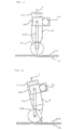
- FIG. 1 shows an example of a pressing device applied to welding operation using a welding torch as a working tool.
- a pressing device 10 is made up of a bracket 16, a servomotor 11, a linear movement mechanism 12 driven by the servomotor 11, a roller support frame 13 fixed to a moving member of the linear movement mechanism 12, and a roller 14 pivotally mounted at the distal end of the roller support frame 13.
- the configuration is such that the bracket 16 of the pressing device 10 is installed at the distal end of a robot arm 100, by which the pressing device 10 is mounted on the robot arm 100.
- the bracket 16 has a working tool mounting section, and in the example shown in FIG. 1, a welding torch 2 is mounted to the working tool mounting section.
- reference numeral 15 denotes a cable for the servomotor 11.
- the roller 14 can move straight via the linear movement mechanism 12 and the roller support frame 13 in the direction such as to come close to or go apart from plate portions of workpieces 1a and 1b.
- the welding torch 2 and the pressing device 10 are fixed to the bracket 16 so that the distal end of the roller 14 is located in the vicinity of the weld point of the welding torch 2.
- the workpieces 1a and 1b are welded by the welding torch 2 while the floating of the workpieces 1a and 1b is prevented by the roller 14 of the pressing device 10 pressing the plate portion of the upper workpiece 1b, and at the same time, the welding torch 2 and the roller 14 are moved along a weld line.
- the positional relationship between the distal end of the welding torch 2 and the roller 14 is variable. In other words, the positional relationship between the weld point and the roller 14 is variable.
- the relationship between the position of weld point and the position at which the plate portion is pressed by the roller 14 can be set optimum for various types of workpieces with a different plate thickness.
- the roller 14 is always brought into contact with the plate portion so as to always press the weld portion to prevent floating, so that a gap between the plate portions of the workpieces 1a and 1b can be regulated.
- this embodiment can also be applied to the case where welding is performed at the welding start point, welding finish point and the like by changing the weld point while the plate portion is pressed by the roller 14. Further, the pressing force can be controlled by controlling a torque delivered by the servomotor 11.
- FIG. 2 shows an example of a pressing device applied to welding operation using a laser welding nozzle as a working tool.
- a laser welding nozzle 3 and the linear movement mechanism 12 are installed to the bracket 16 so that the pressing portion of the roller 14 is located in the vicinity of the focus of weld portion of the laser welding nozzle 3.
- the servomotor 11 is driven so that the roller 14 presses the plate portion of the upper workpiece 1b of the lapped plate portions of the workpieces 1a and 1b, by which a gap between the two lapped plate portions is regulated.
- reference numeral 4 denotes an optical fiber.
- this pressing device can be used for welding workpieces with various shapes and plate thicknesses.
- a pressing device 20 of this embodiment is made up of a bracket 26, a servomotor 21, a linear movement mechanism 22, an attaching member 27, a roller support frame 23, and a roller 24.
- the linear movement mechanism 22 is mounted on a robot by the bracket 26 installed at the distal end of the arm 100 of the robot.
- the attaching member 27 is fixed on the moving side of the linear movement mechanism 22, and the roller support frame 23 is fixed to the attaching member 27.
- a laser welding nozzle 3 is mounted in a working tool mounting section provided on the attaching member 27.
- the roller 24 is pivotally mounted.
- the positional relationship between the distal end of the welding nozzle 3 and the roller 24 is fixed.
- the robot By driving the servomotor 21 so that the rotational motion of the servomotor 21 is converted into linear motion by the linear movement mechanism 22 and thus the welding nozzle 3 and the roller support frame 23 are moved, the distal end of the welding nozzle 3 and the roller 24 are brought close to the plate portions of workpieces 1a and 1b, and further laser welding is performed while the plate portions of the workpieces 1a and 1b are pressed by the roller 24.
- the robot is driven to move the roller 24 and the welding nozzle 3 along a weld line, by which welding operations are carried out.
- the positional relationship between the roller 24 and the laser welding nozzle 3 is always fixed, and welding is performed while the plate portions of the workpieces 1a and 1b are pressed by the roller 24. Therefore, the focus of a laser beam emitted from the laser welding nozzle 3 is located at a substantially fixed position with respect to the workpieces 1a and 1b, so that uniformwelding operation can be performed.
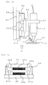
- FIG. 8 shows one example of the aforementioned linear movement mechanism.
- FIG. 8 shows an example of the linear movement mechanism 22 used in the second embodiment shown in FIG. 3, the linear movement mechanism 12 used in the first embodiment shown in FIGS. 1 and 2 is also constructed in the same way.
- a ball screw 22a whose both ends are supported by bearings 22c is disposed in a frame 22e fixed to the bracket 26.
- a slider 22d on the moving side of the linear movement mechanism 22 is fixed.
- a rotational/linear motion converting mechanism such as a rack and pinion can be used.
- FIG. 12 is an explanatory view showing a case where a linear motor is used in place of the linear movement mechanism 22 used in the second embodiment shown in FIG. 3, and FIG. 13 is a sectional view taken in the direction of an arrow A of FIG. 12.
- a base 50 for a linear motor is fixed to the bracket 26, and two rails 51a and 51b are installed in parallel to each other on the base 50.
- a slider 52 which is disposed so as to be opposed to the base 50, is provided with blocks 53a and 53b engaged with the paired rails 51a and 51b.
- a magnet 54a which is an electrical part of the linear motor, is disposed on one face, and a coil 54b is disposed on the other face.
- reference numeral 55 denotes a cover for the linear motor.
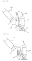
- a pressing device 30 of this embodiment is made up of a bracket 36, a servomotor 31, a speed reducing unit 32, a roller support frame 33, and a roller 34.
- the pressing device 30 is mounted on a robot by the bracket 36 attached to the robot arm 100.
- the bracket 36 is mounted with the speed reducing unit 32 and the servomotor 31. On the output shaft of the speed reducing unit 32 is fixed the roller support frame 33. At the distal end of the roller support frame 33, the roller 34 is pivotally mounted. Also, a laser welding nozzle 3 is installed in a working tool mounting section of the bracket 36, and the distal end of the roller 34 is disposed at a position in the vicinity of the distal end of the laser welding nozzle, that is, in the vicinity of the weld portion.
- the servomotor 31 When the servomotor 31 is driven, the rotational speed thereof is reduced by the speed reducing unit 32 constituting a rotational movement mechanism, and the roller support frame 33 is turned (in the direction perpendicular to the paper face in FIG. 4) via the output shaft of the speed reducing unit 32.
- the roller 34 presses the plate portions of workpieces 1a and 1b to correct a gap between the plate portions of the two workpieces 1a and 1b.
- laser welding is performed by a laser beam emitted from the laser welding nozzle.
- FIG. 5 is a schematic view of the pressing device 30 viewed from the left-hand side of FIG. 4.
- FIG. 6 is an explanatory view in a case where the incident angle of a laser welding nozzle 3 with respect to the workpieces 1a and 1b is changed in FIG. 5.
- the roller support frame 33 can be turned around the output shaft of the speed reducing unit 32 in the same direction as the direction of rotation of the roller 34. Therefore, even when the incident angle of a laser beam from the laser welding nozzle 3 with respect to the workpieces 1a and 1b is changed, or even when the relative angle between the plate portions of the workpieces 1a and 1b and the pressing device 30 is varied at the time of welding, the roller 34 is brought into contact with the plate portions of the workpieces 1a and 1b, so that desired pressing operation can be performed.
- FIG. 7 is an explanatory view of a pressing device in accordance with a fourth embodiment of the present invention.
- This fourth embodiment differs from the third embodiment shown in FIG. 4 in that the laser welding nozzle can also be turned together with the roller support frame.
- a bracket 46 installed at the distal end of the robot arm 100 is mounted with a speed reducing unit 42 and a servomotor 41.
- An attaching member 47 is fixed to the output shaft of the speed reducing unit 42, and a laser welding nozzle 3 is mounted in a working tool mounting section of the attaching member 47.
- a roller support frame 43 is fixed to the attaching member 47.
- a roller 44 is pivotally mounted, and the distal end of the roller 44 is located in the vicinity of the position of the distal end of the laser welding nozzle 3.
- the servomotor 41 When the servomotor 41 is driven, the rotational speed thereof is reduced by the speed reducing unit 42, and the output thereof is taken out to the output shaft to turn the attaching member 47. As a result, the laser welding nozzle 3 and the roller support frame 43, which are attached to the attaching member 47, are turned together with the attaching member 47. The positional relationship between the roller 44 and the laser welding nozzle 3 is not changed, and the roller 44 and the laser welding nozzle 3 are turned while the positional relationship is held.
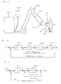
- the pressing device 10 is installed at the distal end of the arm 100 of a robot body (mechanism section) 200.
- the robot body 200 which is connected to a robot controller 201, is controlled by the controller 201. Further, the servomotor 11 of the pressing device 10 is also connected to the robot controller 201 via the motor cable 15.
- the robot controller 201 is connected with a teaching pendant 202.
- the robot body 200 and the pressing device 10 are controlled by the robot controller 201, and are driven by a program or a command sent from the teaching pendant 202.
- the pressing device 10 is connected to what is called an additional axis that the robot controller 201 has, and the servomotor 11 of the pressing device 10 is controlled as the additional axis of the robot controller 201.
- the teaching pendant 202 is not only provided, like the conventional teaching pendant for the robot controller, with various commanding means such as pushbuttons for manually moving the axes of robot, pushbuttons for manually moving a tool center point in the axis directions in an orthogonal coordinate system, and teach buttons for teaching the teaching point as well as display means such as LED but also provided with means for inputting the position, speed, and pressing force of the roller support frame of the pressing device, the distance between the working tool mounted in the working tool mounting section and the plate portions, and the like in relation to the present invention.
- various commanding means such as pushbuttons for manually moving the axes of robot, pushbuttons for manually moving a tool center point in the axis directions in an orthogonal coordinate system
- buttons for teaching the teaching point as well as display means such as LED but also provided with means for inputting the position, speed, and pressing force of the roller support frame of the pressing device, the distance between the working tool mounted in the working tool mounting section and the plate portions, and the like in relation to the present invention.
- the motor cable for connecting the servomotor 11 of the pressing device 10 to the robot controller 201 may be run in the robot body 200 or may be run on the outside.
- the pressing device 10 Since the pressing device 10 is mounted on the robot and is controlled by the robot controller 201, the versatility increases, and the pressing device can be used for various kinds of working merely by changing the teaching of the robot. Since the robot and the pressing device are controlled by a common robot controller, the pressing device can be operated in association with the motion of robot body. Also, when working (welding etc.) is performed on the plate portion of a complicated workpiece with a three-dimensional shape by the motion of robot, working can be performed while the plate portion is pressed to prevent the floating of the portion to be worked, so that the application range of robot can be extended.
- This position and speed control loop for controlling the servomotor that drives the roller support frame of the pressing device in accordance with the first to fourth embodiments, which has been described above, will be explained with reference to a block diagram of FIG. 10.
- This position and speed control loop is the same as the publicly known one.
- Kp of element 301 denotes a position loop gain of a position control loop (proportional control)
- Kv of element 302 denotes a speed loop gain of a speed control loop (proportional-plus-integral control etc.).
- element 303 is an element indicating the transfer function of servomotor, in which Kt denotes a torque constant, and J denotes an inertia.
- Element 304 is an element indicating the transfer function for determining position y from motor speed v. Reference character s denotes the Laplace operator.
- a position feedback value based on the information sent from position and speed detectors installed on the servomotor etc. is subtracted from a movement command r of the roller support frame 13 with respect to the plate portions of the workpieces 1a and 1b.
- a speed command vc is determined.
- speed loop processing is performed to determine a torque command (current command) t, by which the servomotor of the pressing device is driven.
- the pressing device 10 (FIGS. 1 and 2) in accordance with the first embodiment and the pressing device 30 (FIG. 4) in accordance with the third embodiment, by controlling the position of the roller support frame 13, 33, the relative position of the roller 14, 34 of the pressing device with erspect to the working tool (welding torch 2, welding nozzle 3, etc.) and can be controlled at will, so that the optimum working operation of various types of workpieces can be performed.
- the pressing device 20 (FIG. 3) in accordance with the second embodiment and the pressing device 40 (FIG. 7) in accordance with the fourth embodiment, although the relative positional relationship between the working tool (welding torch 2, welding nozzle 3, etc.) and the roller 24, 44 of the pressing device cannot be changed, the position of working tool with respect to the plate portions of the workpieces 1a and 1b can be controlled in accordance with a command.
- the position control can easily be carried out in such a manner that when the roller of pressing device comes to a portion at which the plate portions are held by the jig, the roller is separated from the plate portions to avoid the interference of the roller with the jig, and after the roller has moved to a position at which it does not interfere with the jig, the pressing of the roller on the plate portions is restarted.
- control can be carried out to prevent fluctuations in pressing force of the roller 14, 24, 34, 44 on the workpieces 1a and 1b from occurring.
- the configuration may be such that a torque limiter for controlling the torque command, which is a current command, is provided, and a torque delivered from the servomotor is limited to a preset value set in the torque limiter, by which the pressing force of the roller of pressing device on the workpieces 1a and 1b can be controlled.
- FIG. 11 is a block diagram of a force control loop incorporated into the servomotor control system when the feedback control of the pressing force is carried out.
- a of element 401 denotes a gain (proportional gain) of a force control loop for carrying out the feedback control of pressing force.
- Element 402 is an element indicating the transfer function of motor, in which Kt denotes a torque constant, and J denotes an inertia. Also, Kv of element 403 denotes a speed loop gain of a speed control loop.
- the pressing force of pressing device on the plate portions is estimated by an observer which is incorporated into the servomotor control system to estimate disturbance applied to the servomotor.
- the pressing force estimated by the observer is fed back, by which the pressing force is controlled.
- the observer is publicly known disturbance estimating means, so that detailed explanation thereof is omitted here.
- An estimated pressing force Td estimated by the observer is subtracted from a commanded pressing force Fc given as a target value of pressing force on the plate portions of the workpieces 1a and 1b, and the difference is multiplied by the gain A to determine a speed command vc.
- a value obtained by multiplying a speed feedback value, which is detected by the speed detector and fed back, by the speed loop gain Kv is subtracted from the speed command vc to determine a current command (torque command) t, by which the servomotor is driven.
- the pressing force is estimated by the observer, and feedback control is carried out so that the estimated pressing force coincides with the pressing force preset as the target value.
- this force feedback control since the speed control loop is incorporated as a minor loop for force feedback control in this example, the occurrence of fluctuations in pressing force can be prevented by regulating the speed loop gain Kv of the speed control loop.
Landscapes
- Physics & Mathematics (AREA)
- Optics & Photonics (AREA)
- Engineering & Computer Science (AREA)
- Plasma & Fusion (AREA)
- Mechanical Engineering (AREA)
- Laser Beam Processing (AREA)
- Butt Welding And Welding Of Specific Article (AREA)
Abstract
Description
Claims (14)
with a servomotor for use as a driving source for moving said roller to press said roller on said plate portion in the plate thickness direction.
Applications Claiming Priority (2)
| Application Number | Priority Date | Filing Date | Title |
|---|---|---|---|
| JP2000301780 | 2000-10-02 | ||
| JP2000301780A JP3394750B2 (en) | 2000-10-02 | 2000-10-02 | Work pressing device |
Publications (2)
| Publication Number | Publication Date |
|---|---|
| EP1201352A2 true EP1201352A2 (en) | 2002-05-02 |
| EP1201352A3 EP1201352A3 (en) | 2005-03-09 |
Family
ID=18783255
Family Applications (1)
| Application Number | Title | Priority Date | Filing Date |
|---|---|---|---|
| EP01308388A Withdrawn EP1201352A3 (en) | 2000-10-02 | 2001-10-01 | Pressing device |
Country Status (3)
| Country | Link |
|---|---|
| US (1) | US6965091B2 (en) |
| EP (1) | EP1201352A3 (en) |
| JP (1) | JP3394750B2 (en) |
Cited By (4)
| Publication number | Priority date | Publication date | Assignee | Title |
|---|---|---|---|---|
| WO2004035256A1 (en) * | 2002-10-11 | 2004-04-29 | Daimlerchrysler Ag | Method and device for welding workpieces |
| DE102004003745A1 (en) * | 2004-01-23 | 2005-08-11 | Volkswagen Ag | Hand mountable laser processing unit for welding overlapping galvanized sheets has servo operated tensioning element to hold sheet flanges in position |
| CN113953662A (en) * | 2021-10-14 | 2022-01-21 | 上海华常智能系统有限公司 | Intelligent cold rolling production line laser welding machine equipment |
| DE102015006421B4 (en) | 2015-05-19 | 2024-04-11 | Mercedes-Benz Group AG | Process for joining components |
Families Citing this family (31)
| Publication number | Priority date | Publication date | Assignee | Title |
|---|---|---|---|---|
| AU2002253572A1 (en) * | 2001-04-27 | 2002-11-11 | Honda Giken Kogyo Kabushiki Kaisha | Method and appratus for laser beam welding of overlapping sheets |
| DE50310111D1 (en) * | 2003-08-29 | 2008-08-21 | Trumpf Laser & Systemtechnik | Device for remotely processing workpieces by means of a laser processing beam |
| US7312417B2 (en) * | 2003-09-19 | 2007-12-25 | Daimlerchrysler Ag | Laser beam seam welding with prior laser spot welding |
| US20050230363A1 (en) * | 2004-01-16 | 2005-10-20 | Sascha Debuan | Device for processing work pieces with height offset |
| DE102006014068A1 (en) * | 2006-03-27 | 2007-10-04 | Precitec Kg | Apparatus and method for clamping sheet metal components |
| WO2008018935A2 (en) | 2006-05-08 | 2008-02-14 | Dukane Corporation | Ultrasonic press using servo motor with integrated linear actuator |
| US8052816B2 (en) | 2006-05-08 | 2011-11-08 | Dukane Corporation | Ultrasonic press using servo motor with delayed motion |
| US9144937B2 (en) | 2006-05-08 | 2015-09-29 | Dukane Corporation | Ultrasonic press using servo motor with delayed motion |
| KR100912037B1 (en) * | 2007-12-03 | 2009-08-12 | (주)엘지하우시스 | Method for manufacturing a solar cell module and an equipment therefor |
| KR100986064B1 (en) * | 2008-04-21 | 2010-10-07 | 기아자동차주식회사 | Laser welding machine |
| JP5402100B2 (en) * | 2009-03-06 | 2014-01-29 | 日産自動車株式会社 | Plate material holding device, plate material holding method, laser welding system, and laser welding method |
| ES2658264T3 (en) * | 2009-10-09 | 2018-03-09 | Nihon Shoryoku Kikai Co., Ltd. | Copy devices |
| US8299392B2 (en) * | 2010-04-23 | 2012-10-30 | Benecor, Inc. | Rotating laser welding pressure unit |
| US8245748B2 (en) | 2010-07-14 | 2012-08-21 | Dukane Corporation | Vibration welding system |
| WO2012135732A1 (en) * | 2011-03-30 | 2012-10-04 | Illinois Tool Works Inc. | System for and method of welding large panel assemblies using a welding robot and a pressing component |
| DE102011103246A1 (en) * | 2011-06-03 | 2012-12-06 | Volkswagen Aktiengesellschaft | Method and device for joining components by means of energy-beam welding |
| FR2986170B1 (en) * | 2012-01-26 | 2014-03-07 | Jfp Microtechnic | METHOD AND DEVICE FOR WELDING, IN PARTICULAR BY LASER, WIRES ON A SUBSTRATE |
| US9144860B2 (en) * | 2012-03-29 | 2015-09-29 | Fanuc Robotics America Corporation | Robotic weld gun orientation normalization |
| US9688017B2 (en) | 2013-05-14 | 2017-06-27 | Dukan IAS, LLC | Vibration welders with high frequency vibration, position motion control, and delayed weld motion |
| CN106002038A (en) * | 2016-06-08 | 2016-10-12 | 东莞市川崎机器人有限公司 | Power battery base welding fixture |
| CN107971672A (en) * | 2017-11-30 | 2018-05-01 | 天津市景泰科技发展有限公司 | A kind of frock for automobile hind axle welding |
| US10549481B1 (en) | 2018-12-21 | 2020-02-04 | Dukane Ias, Llc | Systems and methods for low initial weld speed in ultrasonic welding |
| CN109623152B (en) * | 2019-02-14 | 2021-08-24 | 中车青岛四方机车车辆股份有限公司 | Welding auxiliary device, welding system and welding method |
| CN110576261B (en) * | 2019-08-21 | 2021-06-25 | 中车青岛四方机车车辆股份有限公司 | Laser stitch welding device and welding method thereof |
| CN110908012A (en) * | 2019-12-20 | 2020-03-24 | 重庆科杰实业有限责任公司 | An air filter inspection tool |
| CN115302056A (en) * | 2021-05-07 | 2022-11-08 | 四川滕洋智能科技有限公司 | Intersecting line welding device |
| CN113523571B (en) * | 2021-06-30 | 2023-07-14 | 北京航星机器制造有限公司 | Laser welding tooling and welding method for rudder wing product with skin skeleton structure |
| CN113732594A (en) * | 2021-08-13 | 2021-12-03 | 苏州华工自动化技术有限公司 | Automatic frock of zero clearance hot melt welding of multichannel pressfitting |
| US12472580B2 (en) * | 2022-06-01 | 2025-11-18 | Caterpillar Inc. | Laser handheld trimming and welding device |
| CN117300502B (en) * | 2023-11-28 | 2024-02-13 | 武汉创恒激光智能装备有限公司 | Welding workbench for valve core of electromagnetic valve |
| CN119910911B (en) * | 2025-01-24 | 2026-01-06 | 中国科学院宁波材料技术与工程研究所 | Composite structure forming device |
Family Cites Families (12)
| Publication number | Priority date | Publication date | Assignee | Title |
|---|---|---|---|---|
| FR2636554B1 (en) * | 1988-09-20 | 1992-12-04 | Peugeot | DEVICE FOR WELDING SHEETS OR THE LIKE BY A LASER BEAM |
| JPH0480682A (en) | 1990-07-24 | 1992-03-13 | Oki Electric Ind Co Ltd | B-mode display method |
| US5142118A (en) * | 1991-05-14 | 1992-08-25 | Progressive Tool & Industries Co. | Laser welding unit |
| DE4403999C2 (en) * | 1994-02-09 | 1996-12-19 | Ford Werke Ag | Device for welding two- or multi-layer sheet metal components along an interrupted or continuous weld |
| JPH0890264A (en) * | 1994-09-19 | 1996-04-09 | Nissan Motor Co Ltd | Laser welding method |
| US5603853A (en) * | 1995-02-28 | 1997-02-18 | The Twentyfirst Century Corporation | Method of high energy density radiation beam lap welding |
| DE29606375U1 (en) * | 1996-04-04 | 1997-08-28 | Kuka Schweissanlagen Gmbh | Device for welding and / or cutting |
| US5814185A (en) * | 1997-10-01 | 1998-09-29 | Kvaerner U.S. Inc. | Twin sheet thermoformer |
| JPH11226763A (en) | 1998-02-17 | 1999-08-24 | Nissan Motor Co Ltd | Laser welding equipment |
| JP3596329B2 (en) | 1999-02-16 | 2004-12-02 | 日産自動車株式会社 | Laser welding apparatus and laser welding method |
| JP3312896B2 (en) | 1999-12-28 | 2002-08-12 | 川崎重工業株式会社 | Processing head for laser welding robot |
| JP2002086285A (en) | 2000-09-12 | 2002-03-26 | Honda Motor Co Ltd | Laser welding method and apparatus |
-
2000
- 2000-10-02 JP JP2000301780A patent/JP3394750B2/en not_active Expired - Fee Related
-
2001
- 2001-09-28 US US09/964,651 patent/US6965091B2/en not_active Expired - Fee Related
- 2001-10-01 EP EP01308388A patent/EP1201352A3/en not_active Withdrawn
Cited By (6)
| Publication number | Priority date | Publication date | Assignee | Title |
|---|---|---|---|---|
| WO2004035256A1 (en) * | 2002-10-11 | 2004-04-29 | Daimlerchrysler Ag | Method and device for welding workpieces |
| DE102004003745A1 (en) * | 2004-01-23 | 2005-08-11 | Volkswagen Ag | Hand mountable laser processing unit for welding overlapping galvanized sheets has servo operated tensioning element to hold sheet flanges in position |
| DE102004003745B4 (en) * | 2004-01-23 | 2013-10-10 | Volkswagen Ag | Laser processing device |
| DE102015006421B4 (en) | 2015-05-19 | 2024-04-11 | Mercedes-Benz Group AG | Process for joining components |
| CN113953662A (en) * | 2021-10-14 | 2022-01-21 | 上海华常智能系统有限公司 | Intelligent cold rolling production line laser welding machine equipment |
| CN113953662B (en) * | 2021-10-14 | 2024-05-28 | 上海华常智能系统有限公司 | Intelligent cold rolling production line laser welding machine equipment |
Also Published As
| Publication number | Publication date |
|---|---|
| EP1201352A3 (en) | 2005-03-09 |
| JP2002103088A (en) | 2002-04-09 |
| US20020038792A1 (en) | 2002-04-04 |
| JP3394750B2 (en) | 2003-04-07 |
| US6965091B2 (en) | 2005-11-15 |
Similar Documents
| Publication | Publication Date | Title |
|---|---|---|
| US6965091B2 (en) | Pressing device | |
| US5961858A (en) | Laser welding apparatus employing a tilting mechanism | |
| US11298781B2 (en) | Workpiece rotating appartus and robot system | |
| EP1219384B1 (en) | Laser-welding head | |
| US5560843A (en) | Frame construction and a machining device provided with it | |
| JP7000361B2 (en) | Follow-up robot and work robot system | |
| JP4137386B2 (en) | Method for controlling numerically controlled machine tool and numerically controlled machine tool | |
| EP1600241A2 (en) | Focus adjuster for laser beam machine | |
| WO2021235331A1 (en) | Following robot | |
| JP7441172B2 (en) | Workpiece processing device with servoelastic actuator system having a compliant elastic member and a weight-compensating elastic member | |
| EP0437676A1 (en) | Laser cutting machine | |
| JP3864240B2 (en) | Welding method | |
| US5093549A (en) | Laser cutting machine | |
| KR100602200B1 (en) | Hybrid welding controller | |
| KR101863150B1 (en) | Welding apparatus | |
| KR20190081044A (en) | Apparatus for automatically adjusting work position | |
| JPH10166075A (en) | Method for punching and device therefor | |
| JP2018187715A (en) | Robot device | |
| JPH0825260A (en) | Deflection correction method for industrial robot | |
| JP7787052B2 (en) | Vertical welding apparatus and method for controlling vertical welding apparatus | |
| US20240149374A1 (en) | Measuring device and method for performing measurements on a workpiece as well as machining system and welding method | |
| US20250135638A1 (en) | Work robot system | |
| JPS5854948B2 (en) | Machine tool feed device | |
| JPH079304A (en) | Correcting method for correctingly positioning elastic deformation of mechanical structure | |
| JP7193361B2 (en) | position controller |
Legal Events
| Date | Code | Title | Description |
|---|---|---|---|
| PUAI | Public reference made under article 153(3) epc to a published international application that has entered the european phase |
Free format text: ORIGINAL CODE: 0009012 |
|
| AK | Designated contracting states |
Kind code of ref document: A2 Designated state(s): AT BE CH CY DE DK ES FI FR GB GR IE IT LI LU MC NL PT SE TR |
|
| AX | Request for extension of the european patent |
Free format text: AL;LT;LV;MK;RO;SI |
|
| RAP1 | Party data changed (applicant data changed or rights of an application transferred) |
Owner name: FANUC LTD |
|
| PUAL | Search report despatched |
Free format text: ORIGINAL CODE: 0009013 |
|
| AK | Designated contracting states |
Kind code of ref document: A3 Designated state(s): AT BE CH CY DE DK ES FI FR GB GR IE IT LI LU MC NL PT SE TR |
|
| AX | Request for extension of the european patent |
Extension state: AL LT LV MK RO SI |
|
| RIC1 | Information provided on ipc code assigned before grant |
Ipc: 7B 23K 26/42 B Ipc: 7B 23K 26/02 B Ipc: 7B 23Q 3/06 A |
|
| 17P | Request for examination filed |
Effective date: 20050615 |
|
| AKX | Designation fees paid |
Designated state(s): DE |
|
| GRAP | Despatch of communication of intention to grant a patent |
Free format text: ORIGINAL CODE: EPIDOSNIGR1 |
|
| RAP1 | Party data changed (applicant data changed or rights of an application transferred) |
Owner name: FANUC CORPORATION |
|
| STAA | Information on the status of an ep patent application or granted ep patent |
Free format text: STATUS: THE APPLICATION IS DEEMED TO BE WITHDRAWN |
|
| 18D | Application deemed to be withdrawn |
Effective date: 20101012 |