EP1200181B1 - Improved valve members for a homogenization valve - Google Patents
Improved valve members for a homogenization valve Download PDFInfo
- Publication number
- EP1200181B1 EP1200181B1 EP00943396A EP00943396A EP1200181B1 EP 1200181 B1 EP1200181 B1 EP 1200181B1 EP 00943396 A EP00943396 A EP 00943396A EP 00943396 A EP00943396 A EP 00943396A EP 1200181 B1 EP1200181 B1 EP 1200181B1
- Authority
- EP
- European Patent Office
- Prior art keywords
- valve
- gaps
- members
- valve member
- compressible
- Prior art date
- Legal status (The legal status is an assumption and is not a legal conclusion. Google has not performed a legal analysis and makes no representation as to the accuracy of the status listed.)
- Expired - Lifetime
Links
- 238000000265 homogenisation Methods 0.000 title abstract description 15
- 239000012530 fluid Substances 0.000 claims abstract description 25
- 239000000463 material Substances 0.000 claims description 22
- 238000000034 method Methods 0.000 claims description 12
- 229910001220 stainless steel Inorganic materials 0.000 claims description 3
- 239000010935 stainless steel Substances 0.000 claims description 3
- UONOETXJSWQNOL-UHFFFAOYSA-N tungsten carbide Chemical compound [W+]#[C-] UONOETXJSWQNOL-UHFFFAOYSA-N 0.000 claims description 2
- 238000005452 bending Methods 0.000 claims 1
- 125000006850 spacer group Chemical group 0.000 description 12
- 235000013336 milk Nutrition 0.000 description 5
- 239000008267 milk Substances 0.000 description 5
- 210000004080 milk Anatomy 0.000 description 5
- 230000008901 benefit Effects 0.000 description 3
- 244000145845 chattering Species 0.000 description 3
- 239000006185 dispersion Substances 0.000 description 3
- 239000000839 emulsion Substances 0.000 description 3
- 230000008569 process Effects 0.000 description 3
- 230000015572 biosynthetic process Effects 0.000 description 2
- 238000010276 construction Methods 0.000 description 2
- 230000002939 deleterious effect Effects 0.000 description 2
- 230000001965 increasing effect Effects 0.000 description 2
- 238000011144 upstream manufacturing Methods 0.000 description 2
- 230000001133 acceleration Effects 0.000 description 1
- WYTGDNHDOZPMIW-RCBQFDQVSA-N alstonine Natural products C1=CC2=C3C=CC=CC3=NC2=C2N1C[C@H]1[C@H](C)OC=C(C(=O)OC)[C@H]1C2 WYTGDNHDOZPMIW-RCBQFDQVSA-N 0.000 description 1
- 229940069428 antacid Drugs 0.000 description 1
- 239000003159 antacid agent Substances 0.000 description 1
- 230000000712 assembly Effects 0.000 description 1
- 238000000429 assembly Methods 0.000 description 1
- 238000000576 coating method Methods 0.000 description 1
- 238000004891 communication Methods 0.000 description 1
- 230000006835 compression Effects 0.000 description 1
- 238000007906 compression Methods 0.000 description 1
- 238000005336 cracking Methods 0.000 description 1
- 230000007812 deficiency Effects 0.000 description 1
- 230000006872 improvement Effects 0.000 description 1
- 230000001939 inductive effect Effects 0.000 description 1
- 238000003754 machining Methods 0.000 description 1
- 238000004519 manufacturing process Methods 0.000 description 1
- 230000007246 mechanism Effects 0.000 description 1
- 235000021243 milk fat Nutrition 0.000 description 1
- 238000002156 mixing Methods 0.000 description 1
- 230000002093 peripheral effect Effects 0.000 description 1
- 239000000049 pigment Substances 0.000 description 1
- 229920002545 silicone oil Polymers 0.000 description 1
- 239000007779 soft material Substances 0.000 description 1
- 238000003466 welding Methods 0.000 description 1
Images




Classifications
-
- B—PERFORMING OPERATIONS; TRANSPORTING
- B01—PHYSICAL OR CHEMICAL PROCESSES OR APPARATUS IN GENERAL
- B01F—MIXING, e.g. DISSOLVING, EMULSIFYING OR DISPERSING
- B01F25/00—Flow mixers; Mixers for falling materials, e.g. solid particles
- B01F25/40—Static mixers
- B01F25/44—Mixers in which the components are pressed through slits
- B01F25/442—Mixers in which the components are pressed through slits characterised by the relative position of the surfaces during operation
- B01F25/4423—Mixers in which the components are pressed through slits characterised by the relative position of the surfaces during operation the surfaces being part of a valve construction, formed by opposed members in contact, e.g. automatic positioning caused by spring pressure
-
- B—PERFORMING OPERATIONS; TRANSPORTING
- B01—PHYSICAL OR CHEMICAL PROCESSES OR APPARATUS IN GENERAL
- B01F—MIXING, e.g. DISSOLVING, EMULSIFYING OR DISPERSING
- B01F25/00—Flow mixers; Mixers for falling materials, e.g. solid particles
- B01F25/40—Static mixers
- B01F25/44—Mixers in which the components are pressed through slits
- B01F25/441—Mixers in which the components are pressed through slits characterised by the configuration of the surfaces forming the slits
- B01F25/4412—Mixers in which the components are pressed through slits characterised by the configuration of the surfaces forming the slits the slits being formed between opposed planar surfaces, e.g. pushed again each other by springs
- B01F25/44121—Mixers in which the components are pressed through slits characterised by the configuration of the surfaces forming the slits the slits being formed between opposed planar surfaces, e.g. pushed again each other by springs with a plurality of parallel slits, e.g. formed between stacked plates
-
- Y—GENERAL TAGGING OF NEW TECHNOLOGICAL DEVELOPMENTS; GENERAL TAGGING OF CROSS-SECTIONAL TECHNOLOGIES SPANNING OVER SEVERAL SECTIONS OF THE IPC; TECHNICAL SUBJECTS COVERED BY FORMER USPC CROSS-REFERENCE ART COLLECTIONS [XRACs] AND DIGESTS
- Y10—TECHNICAL SUBJECTS COVERED BY FORMER USPC
- Y10T—TECHNICAL SUBJECTS COVERED BY FORMER US CLASSIFICATION
- Y10T137/00—Fluid handling
- Y10T137/8593—Systems
- Y10T137/86493—Multi-way valve unit
- Y10T137/86718—Dividing into parallel flow paths with recombining
- Y10T137/86734—With metering feature
Definitions
- Homogenization is the process of breaking down and blending components within a fluid.
- One familiar example is milk homogenization in which milk fat globules are broken-up and distributed into the bulk of the milk.
- Homogenization is also used to process other emulsions such as silicone oil and process dispersions such as pigments, antacids, and some paper coatings.
- the most common device for performing homogenization is a homogenization valve.
- the emulsion or dispersion is introduced under high pressure into the valve, which functions as a flow restrictor to generate intense turbulence.
- the high pressure fluid is forced out through a usually narrow valve gap into a lower pressure environment.
- Newer homogenization valve designs have been more successful at accommodating high flow rates while maintaining near optimal valve gaps. Some of the best examples of these designs are disclosed in United States Patent Nos. 4,352,573 and 4,383,769 to William D. Pandolfe and assigned to the instant assignee.
- Multiple annular valve members are stacked one on top of the other.
- the central holes of the stacked members define a common, high pressure, chamber.
- Annular grooves are formed on the top and/or bottom surfaces of each valve member, concentric with the central hole.
- the grooves are in fluid communication with each other via axially directed circular ports that extend through the members, and together the grooves and ports define a second, low pressure, chamber.
- each valve member the wall between the central hole and the grooves is chamfered to provide knife edges.
- Each knife edge forms a valve seat spaced a small distance from an opposed valve surface on the adjacent valve member. In this design, higher flow rates are accommodated simply by adding more valve members to the stack.
- prior art valves have been prone to noise emissions. It has been found that the noise is attributable, at least in part, to the environment into which the homogenized fluid is expressed. More particularly, the prior valves have expressed the fluid into a relatively closed environment between the valve members. This has been found to cause chattering of the valve members which can damage the valve members, emit noise, and produce other deleterious effects in the operation of the valve.
- valve member for a stacked valve member homogenizing valve, the valve member comprising a valve seat to define a gap with an opposed valve surface, characterised in that a part of the valve member is formed of a compressible material thereby forming compressible spacing means for maintaining the gap.
- the preferred valve member includes opposite faces.
- the first face includes the valve seat while the second face includes the valve surface to define respective valve gaps when valve members are stacked on one another.
- a homogenizing valve comprising: a housing; a plurality of valve members within the housing having valve seats defining gaps with valve surfaces when stacked on one another; and an actuator which acts on the valve members to control the width of the gaps, characterised in that a part of each valve member is formed from a compressible material thereby forming a compressible spacing means for maintaining the gaps.
- a method of homogenizing a fluid with stacked valve members comprising: expressing a fluid through a plurality of gaps from a high pressure volume to a low pressure volume characterised in that a part of each valve member is formed of a compressible material forming spacing elements of the valve members, the spacing elements being compressed with an actuator to control the width of substantially all of the gaps.
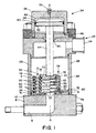
- Fig. 1 is a cross sectional view of a primary valve assembly 2 for use in a homogenizing system (complete system not shown).
- the previous design of valve members is shown on the left side of longitudinal axis A-A while the inventive valve members of the present invention are illustrated on the right side.
- valve members 4 constructed according to the principles disclosed in the '769 patent, many of the details of these members being better understood with reference to Fig. 2.
- an inlet port 6, formed in an inlet flange 8, conveys a high pressure fluid to a valve member stack 10.
- the high pressure fluid is introduced into an inner chamber 12 defined by the central holes 14 formed through the generally annular valve members 4.
- the high pressure fluid is then expressed through valve gaps 16 into a low pressure chamber 18 that is defined by the axial ports 20 through the valve members 4 and the annular grooves 22 in the valve members 4.
- the fluid passing into the low pressure chamber 18 enters a discharge port 24 in a discharge flange assembly 25.
- the stack 10 of valve members 4 is sealed against the inlet flange 8 via a base valve member 26 using o-ring 30.
- the base valve member 26 is sealed against the housing 28 via o-ring 31.
- This base valve member 26 is costly to manufacture because of its complex shape.
- the top-most valve member 4 engages a top valve plug 32 that seals across the inner chamber 12.
- An o-ring 33 provides a fluid seal between the top-most valve member 4 and the top valve plug 32.
- This top valve plug 32 is hydraulically or pneumatically urged by actuator assembly 34, which comprises an actuator body 36 surrounding an actuator piston 38 sealed via an o-ring 40 and a backup o-ring 42.
- a vent plug 39 is provided in the actuator body 36 to bleed air from the cavity 48.
- the piston 38 is connected to the top plug 32 via an actuator rod 44.
- An actuator guide plate 46 sits between the actuator body 36 and the discharge flange assembly 25.
- a rod seal 45 provides a fluid seal between the actuator rod 44 and the discharge flange assembly 25.
- the base valve member 26 and other valve members 4 are aligned with respect to each other and maintained in the stack formation by serpentine valve springs 50 that are confined within cooperating spring-grooves 52, 54 formed in the otherwise flat peripheral rim surfaces of each valve member 4.
- valve members 56 of the present invention also form a stack of valve members 58 as illustrated on the right side of the valve of Fig. 1 and Fig. 3.
- the valve members 58 provide improved efficiency and reduced chattering of the stack due to the layout of the valve members.
- these valve members 58 are configured to be retrofitted within existing assemblies 2.
- valve gaps 60 and valve springs 62 are provided between each valve member pair.
- the gaps 60 provided between each valve member pair form a restricted passageway through which the emulsion or dispersion is expressed to the low pressure chamber 65.
- the gaps 60 can be formed as illustrated in Fig. 3 of the '769 patent.
- the gaps 60 are formed as disclosed in commonly assigned U.S. Pat. 5,749,650, filed March 13, 1997, and U.S. Pat. 5,899,564 filed May 11, 1998.
- the height of the gap 60 is preferably between 0.0013 and 0.0018 inches, usually about 0.0015 inches, but in any event less than 0.003 inches.
- This dimension is defined as the vertical distance between the valve seat or land and the opposed, largely flat, valve surface on opposite faces of the valve member.
- the valve seat is a knife-edge configuration.
- the valve seat or land 64 is chamfered at 60° angle sloping toward the valve surface 66.
- the valve seat 64 is flat across a distance of ideally approximately 0.015 to 0.020 inches, but less than 0.06 inches.
- the valve seat 64 slopes away from the valve surface 66 at an angle from 5 to 90° or greater, approximately 60° in the illustrated embodiment.
- the valve surface 66 is similarly constructed.
- the downstream terminations of valve surfaces overlap valve seats or lands by no more than 0.025 inches.
- the downstream terminations of the valve surfaces 66 overlap the valve seats 64 by at least a height of the valve gaps 60. It has also been found that no overlap between the valve seats 64 and valve surfaces 66 can be effective as well.
- valve springs 62 are positioned upstream from the valve gaps 60, i . e ., on the high pressure side of the valve gaps.
- Prior art designs have expressed the fluid into a closed environment between the valve members. In the present invention, however, the high pressure fluid passes through the spring region before being expressed through the valve gaps 60. Accordingly, the turbulent expressed fluid is in the open chamber 64 and not over the springs, an arrangement which has been found to reduce chatter of the valve members 56. Chattering of the valve members 56 is undesirable as such can damage the valve members, emit noise, and produce other deleterious effects in the operation of the valve 2.
- the distance from the center of the high pressure chamber 12 to the valve gaps 16, 60 is substantially the same such that the prior art valve members 4 can be replaced by the inventive valve members 56 without any or only minor adjustment to the actuator pressure required to adjust the valve gaps.
- the inventive valve members 56 include spacing elements or pads which allow the valve members to be compressed by the actuator 34 such that substantially all the valve gaps 60 are adjusted to compensate for wear. This has the advantage of maintaining a separational distance (and often optimized) between the valve seat and valve surface for a preferred pressure despite wear which tends to widen the gaps.
- Figs. 3-6 illustrate exemplary spacer pads 68 that form part of valve member 56. Area 70 is machined off leaving the spacer pads 68. Valve members 56 are stacked on one another with spacer pads 68 of one valve member contacting the underside 72 of a contiguous valve member to form the valve gaps 60 between the valve seat 64 and opposing valve surface 66. Alternatively, spacers pads 68 can be a separate element coupled to or positioned adjacent the valve members 56. The spacer pads 68 are small enough such that they can be compressed by the actuator 34. In a preferred embodiment of the present invention, each spacer pad 68 has a surface area of approximately 11 mm 2 that touches the underside 72 of a contiguous valve member 56 when assembled. This allows each spacer pad 68 to be compressed up to about 0.002 inches (0.0508 mm).
- the spacer element can comprise a continuous, relatively thin, annular lip which is compressed to compensate for wear of the valve surfaces and seats.
- valve springs 62 help align the stack formation as before. Additionally, the valve spring 62 ends can be bent, for example, 90 degrees, and inserted into machined notches or pockets 74 (see Figs. 3, 4 and 6) in adjacent valve members such that the stack of valve members maintains preferable angular alignment. Such a configuration prevents rotation of the valve members 56 relative to one another. That is to say, the spacer pads 68 are aligned in vertical rows when preferably aligned.
- the base valve member 76 is an improvement over the prior art base valve member 26. More particularly, the member 76 is similar to the other valve members 56 except that there is no machining on the bottom surface. Thus, an expensive part to machine is beneficially avoided.
- a valve guide 78 sealed against the housing 28 via o-ring 30 and against the base valve member 76 via gasket 80 is provided to center the base valve member and hence the stack 58 of valve members.
- the valve guide 78 is formed from a less expensive material, such as stainless steel, thereby saving material cost over the prior art base valve member 26.
- Fig. 8 illustrates an alternative embodiment of the valve member, designated by reference numeral 56'.
- This valve member 56' illustrates the spacer pads 68 adjacent the high pressure volume 12 and the valve seat 64 and valve surface 66 adjacent the low pressure volume 65.
- the valve member 56' is formed from at least two materials: a hard, durable material forming the valve seat and surface to minimize wear thereof and a relatively soft, compressible material forming the spacer pads to allow compression without cracking thereof.
- an inner ring 82 of a relatively soft material, such as stainless steel is inserted into an outer ring 84 of a harder, more durable material, such as tungsten-carbide.
- the hard material has a Rockwell A-scale hardness number of greater than 90 and the compressible material has a Rockwell A-scale hardness number of not greater than 80.
- the rings 82, 84 are maintained in position by an interference fit or other suitable methods, such as welding.
- inventive concepts discussed supra can be applied to other homogenizing valve configurations, such as disclosed in U.S. Application Serial No. 09/350,503 entitled "HOMOGENIZATION VALVE WITH OUTSIDE HIGH PRESSURE VOLUME". More particularly, fluid can be expressed from an outside high pressure volume outside the stacked valve members to a low pressure volume inside the valve members. In that case, preferably the springs are configured to be within the high pressure volume and the spacing elements are adjacent the low pressure volume.
Landscapes
- Chemical & Material Sciences (AREA)
- Dispersion Chemistry (AREA)
- Chemical Kinetics & Catalysis (AREA)
- Lift Valve (AREA)
- Multiple-Way Valves (AREA)
- Check Valves (AREA)
- Temperature-Responsive Valves (AREA)
- Dairy Products (AREA)
Abstract
Description
- Homogenization is the process of breaking down and blending components within a fluid. One familiar example is milk homogenization in which milk fat globules are broken-up and distributed into the bulk of the milk. Homogenization is also used to process other emulsions such as silicone oil and process dispersions such as pigments, antacids, and some paper coatings.
- The most common device for performing homogenization is a homogenization valve. The emulsion or dispersion is introduced under high pressure into the valve, which functions as a flow restrictor to generate intense turbulence. The high pressure fluid is forced out through a usually narrow valve gap into a lower pressure environment.
- Homogenization occurs in the region surrounding the valve gap. The fluid undergoes rapid acceleration coupled with extreme drops in pressure. Theories have suggested that both turbulence and cavitation in this region are the mechanisms that facilitate the homogenization.
- Early homogenization valves had a single valve plate that was thrust against a valve seat by some, typically mechanical or hydraulic, actuating system. Milk, for example, was expressed through an annular aperture or valve slit between the valve and the valve seat.
- While offering the advantage of a relatively simple construction, the early valves could not efficiently handle high milk flow rates. Homogenization occurs most efficiently with comparatively small valve gaps, which limits the milk flow rate for a given pressure. Thus, higher flow rates could only be achieved by increasing the diameter or size of a single homogenizing valve.
- Newer homogenization valve designs have been more successful at accommodating high flow rates while maintaining near optimal valve gaps. Some of the best examples of these designs are disclosed in United States Patent Nos. 4,352,573 and 4,383,769 to William D. Pandolfe and assigned to the instant assignee. Multiple annular valve members are stacked one on top of the other. The central holes of the stacked members define a common, high pressure, chamber. Annular grooves are formed on the top and/or bottom surfaces of each valve member, concentric with the central hole. The grooves are in fluid communication with each other via axially directed circular ports that extend through the members, and together the grooves and ports define a second, low pressure, chamber. In each valve member, the wall between the central hole and the grooves is chamfered to provide knife edges. Each knife edge forms a valve seat spaced a small distance from an opposed valve surface on the adjacent valve member. In this design, higher flow rates are accommodated simply by adding more valve members to the stack.
- Prior art systems have suffered from at least two deficiencies. First, maintaining an optimized distance between substantially all of the valve gaps has not been achieved. For example, as disclosed in the '769 patent, in situations where the valve surface and valve seat wear down due to extended use, the actuator flexes the top valve members to close only a desired number of valve gaps to maintain the pressure differential so that the fluid is properly homogenized. It would be preferable to adjust substantially all of the valve gaps to maintain a predetermined separational distance between the valve seat and valve surface.
- Second, prior art valves have been prone to noise emissions. It has been found that the noise is attributable, at least in part, to the environment into which the homogenized fluid is expressed. More particularly, the prior valves have expressed the fluid into a relatively closed environment between the valve members. This has been found to cause chattering of the valve members which can damage the valve members, emit noise, and produce other deleterious effects in the operation of the valve.
- In accordance with one aspect of the invention there is provided a valve member for a stacked valve member homogenizing valve, the valve member comprising a valve seat to define a gap with an opposed valve surface, characterised in that a part of the valve member is formed of a compressible material thereby forming compressible spacing means for maintaining the gap.
- The preferred valve member includes opposite faces. The first face includes the valve seat while the second face includes the valve surface to define respective valve gaps when valve members are stacked on one another.
- In accordance with another aspect of the present invention there is provided a homogenizing valve, comprising: a housing; a plurality of valve members within the housing having valve seats defining gaps with valve surfaces when stacked on one another; and an actuator which acts on the valve members to control the width of the gaps, characterised in that a part of each valve member is formed from a compressible material thereby forming a compressible spacing means for maintaining the gaps.
- In accordance with yet another aspect of the present invention there is provided a method of homogenizing a fluid with stacked valve members, comprising: expressing a fluid through a plurality of gaps from a high pressure volume to a low pressure volume characterised in that a part of each valve member is formed of a compressible material forming spacing elements of the valve members, the spacing elements being compressed with an actuator to control the width of substantially all of the gaps.
- The above and other features of the invention including various novel details of construction and combinations of parts, and other advantages, will now be more particularly described with reference to the accompanying drawings and pointed out in the claims. It will be understood that the particular method and device embodying the invention are shown by way of illustration and not as a limitation of the invention. The principles and features of this invention may be employed in various and numerous embodiments without departing from the scope of the invention.
- In the accompanying drawings, reference characters refer to the same parts throughout the different views. The drawings are not necessarily to scale; emphasis has instead been placed upon illustrating the principles of the invention. Of the drawings:
- Fig. 1 is a cross sectional view of a homogenization valve illustrating prior art valve members on the left side of longitudinal axis A-A and inventive valve members in accordance with the present invention on the right side of the longitudinal axis A-A;
- Fig. 2 is a cross sectional isometric view of the prior art valve members shown in Fig. 1;
- Fig. 3 is a cross sectional isometric view of the preferred valve members of the present invention also shown in Fig. 1;
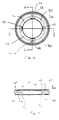
- Fig. 4 is a plan view of an exemplary valve member with spacer pads in accordance with the present invention;
- Fig. 5 is a cross sectional view taken along line 5-5 of Fig. 4;
- Fig. 6 is a cross sectional view taken along line 6-6 of Fig. 4;
- Fig. 7 is an enlarged view of the encircled area referenced as "A" of Fig. 6; and
- Fig. 8 is a cross sectional view of an alternative valve member.
-
- Fig. 1 is a cross sectional view of a primary valve assembly 2 for use in a homogenizing system (complete system not shown). The previous design of valve members is shown on the left side of longitudinal axis A-A while the inventive valve members of the present invention are illustrated on the right side.
- The prior art valve includes
valve members 4 constructed according to the principles disclosed in the '769 patent, many of the details of these members being better understood with reference to Fig. 2. - With reference to both Figs. 1 and 2, an
inlet port 6, formed in aninlet flange 8, conveys a high pressure fluid to avalve member stack 10. The high pressure fluid is introduced into aninner chamber 12 defined by thecentral holes 14 formed through the generallyannular valve members 4. The high pressure fluid is then expressed throughvalve gaps 16 into alow pressure chamber 18 that is defined by theaxial ports 20 through thevalve members 4 and theannular grooves 22 in thevalve members 4. The fluid passing into thelow pressure chamber 18 enters adischarge port 24 in adischarge flange assembly 25. - The
stack 10 ofvalve members 4 is sealed against theinlet flange 8 via abase valve member 26 using o-ring 30. Thebase valve member 26 is sealed against thehousing 28 via o-ring 31. Thisbase valve member 26 is costly to manufacture because of its complex shape. Thetop-most valve member 4 engages atop valve plug 32 that seals across theinner chamber 12. An o-ring 33 provides a fluid seal between thetop-most valve member 4 and thetop valve plug 32. Thistop valve plug 32 is hydraulically or pneumatically urged byactuator assembly 34, which comprises anactuator body 36 surrounding anactuator piston 38 sealed via an o-ring 40 and a backup o-ring 42. Avent plug 39 is provided in theactuator body 36 to bleed air from thecavity 48. - The
piston 38 is connected to thetop plug 32 via anactuator rod 44. An actuator guide plate 46 sits between theactuator body 36 and thedischarge flange assembly 25. Arod seal 45 provides a fluid seal between theactuator rod 44 and thedischarge flange assembly 25. By varying the pressure of a hydraulic fluid or pneumatically incavity 48 through a fluid port (not shown), the size of thevalve gaps 16 may be modulated by inducing the axial flexing of thevalve members 4. For example, as disclosed in the '769 patent, the downward force flexes the top valve members to close the desired number of valve gaps to adjust the pressure differential. This design has not been able to modulate substantially all of the gaps, which is desirable for optimal performance of the valve. - The
base valve member 26 andother valve members 4 are aligned with respect to each other and maintained in the stack formation by serpentine valve springs 50 that are confined within cooperating spring-grooves 52, 54 formed in the otherwise flat peripheral rim surfaces of eachvalve member 4. - The
inventive valve members 56 of the present invention also form a stack ofvalve members 58 as illustrated on the right side of the valve of Fig. 1 and Fig. 3. Generally, as will be described below, thevalve members 58 provide improved efficiency and reduced chattering of the stack due to the layout of the valve members. Beneficially, thesevalve members 58 are configured to be retrofitted within existing assemblies 2. - As illustrated, the
valve gaps 60 and valve springs 62 are provided between each valve member pair. Thegaps 60 provided between each valve member pair form a restricted passageway through which the emulsion or dispersion is expressed to thelow pressure chamber 65. Thegaps 60 can be formed as illustrated in Fig. 3 of the '769 patent. Preferably, thegaps 60 are formed as disclosed in commonly assigned U.S. Pat. 5,749,650, filed March 13, 1997, and U.S. Pat. 5,899,564 filed May 11, 1998. - More specifically, the height of the
gap 60 is preferably between 0.0013 and 0.0018 inches, usually about 0.0015 inches, but in any event less than 0.003 inches. This dimension is defined as the vertical distance between the valve seat or land and the opposed, largely flat, valve surface on opposite faces of the valve member. Experimentation has shown that the gap should not be simply increased beyond 0.003 inches to obtain higher flow rates since such increases will lead to lower homogenization efficiencies. - In the preferred embodiment, the valve seat is a knife-edge configuration. With reference to Figs. 5-7, on the upstream, high pressure side of the gap, the valve seat or land 64 is chamfered at 60° angle sloping toward the valve surface 66. In the gap, the valve seat 64 is flat across a distance of ideally approximately 0.015 to 0.020 inches, but less than 0.06 inches. On the downstream, low pressure side of the
gap 60, the valve seat 64 slopes away from the valve surface 66 at an angle from 5 to 90° or greater, approximately 60° in the illustrated embodiment. The valve surface 66 is similarly constructed. The downstream terminations of valve surfaces overlap valve seats or lands by no more than 0.025 inches. Preferably, the downstream terminations of the valve surfaces 66 overlap the valve seats 64 by at least a height of thevalve gaps 60. It has also been found that no overlap between the valve seats 64 and valve surfaces 66 can be effective as well. - It is significant that the valve springs 62 are positioned upstream from the
valve gaps 60, i.e., on the high pressure side of the valve gaps. Prior art designs have expressed the fluid into a closed environment between the valve members. In the present invention, however, the high pressure fluid passes through the spring region before being expressed through thevalve gaps 60. Accordingly, the turbulent expressed fluid is in the open chamber 64 and not over the springs, an arrangement which has been found to reduce chatter of thevalve members 56. Chattering of thevalve members 56 is undesirable as such can damage the valve members, emit noise, and produce other deleterious effects in the operation of the valve 2. - It should also be noted that the distance from the center of the
high pressure chamber 12 to thevalve gaps art valve members 4 can be replaced by theinventive valve members 56 without any or only minor adjustment to the actuator pressure required to adjust the valve gaps. - The
inventive valve members 56 include spacing elements or pads which allow the valve members to be compressed by theactuator 34 such that substantially all thevalve gaps 60 are adjusted to compensate for wear. This has the advantage of maintaining a separational distance (and often optimized) between the valve seat and valve surface for a preferred pressure despite wear which tends to widen the gaps. - Figs. 3-6 illustrate
exemplary spacer pads 68 that form part ofvalve member 56.Area 70 is machined off leaving thespacer pads 68.Valve members 56 are stacked on one another withspacer pads 68 of one valve member contacting theunderside 72 of a contiguous valve member to form thevalve gaps 60 between the valve seat 64 and opposing valve surface 66. Alternatively,spacers pads 68 can be a separate element coupled to or positioned adjacent thevalve members 56. Thespacer pads 68 are small enough such that they can be compressed by theactuator 34. In a preferred embodiment of the present invention, eachspacer pad 68 has a surface area of approximately 11 mm2 that touches theunderside 72 of acontiguous valve member 56 when assembled. This allows eachspacer pad 68 to be compressed up to about 0.002 inches (0.0508 mm). - In alternative embodiments, the spacer element can comprise a continuous, relatively thin, annular lip which is compressed to compensate for wear of the valve surfaces and seats.
- The valve springs 62 help align the stack formation as before. Additionally, the
valve spring 62 ends can be bent, for example, 90 degrees, and inserted into machined notches or pockets 74 (see Figs. 3, 4 and 6) in adjacent valve members such that the stack of valve members maintains preferable angular alignment. Such a configuration prevents rotation of thevalve members 56 relative to one another. That is to say, thespacer pads 68 are aligned in vertical rows when preferably aligned. - Returning to Fig. 1, the
base valve member 76 is an improvement over the prior artbase valve member 26. More particularly, themember 76 is similar to theother valve members 56 except that there is no machining on the bottom surface. Thus, an expensive part to machine is beneficially avoided. Avalve guide 78 sealed against thehousing 28 via o-ring 30 and against thebase valve member 76 viagasket 80 is provided to center the base valve member and hence thestack 58 of valve members. Preferably, thevalve guide 78 is formed from a less expensive material, such as stainless steel, thereby saving material cost over the prior artbase valve member 26. - Fig. 8 illustrates an alternative embodiment of the valve member, designated by reference numeral 56'. This valve member 56' illustrates the
spacer pads 68 adjacent thehigh pressure volume 12 and the valve seat 64 and valve surface 66 adjacent thelow pressure volume 65. The valve member 56' is formed from at least two materials: a hard, durable material forming the valve seat and surface to minimize wear thereof and a relatively soft, compressible material forming the spacer pads to allow compression without cracking thereof. Preferably, aninner ring 82 of a relatively soft material, such as stainless steel, is inserted into an outer ring 84 of a harder, more durable material, such as tungsten-carbide. In a preferred embodiment, the hard material has a Rockwell A-scale hardness number of greater than 90 and the compressible material has a Rockwell A-scale hardness number of not greater than 80. Therings 82, 84 are maintained in position by an interference fit or other suitable methods, such as welding. - It will be understood that the inventive concepts discussed supra can be applied to other homogenizing valve configurations, such as disclosed in U.S. Application Serial No. 09/350,503 entitled "HOMOGENIZATION VALVE WITH OUTSIDE HIGH PRESSURE VOLUME". More particularly, fluid can be expressed from an outside high pressure volume outside the stacked valve members to a low pressure volume inside the valve members. In that case, preferably the springs are configured to be within the high pressure volume and the spacing elements are adjacent the low pressure volume.
Claims (22)
- A valve member (56) for a stacked valve member homogenizing valve, the valve member (56) comprising a valve seat (64) to define a gap (60) with an opposed valve surface (66), characterised in that a part (68) of the valve member (56) is formed of a compressible material thereby forming compressible spacing means (68) for maintaining the gap (60).
- A homogenizing valve, comprising:characterised in that a part (68) of each valve member (56) is formed from a compressible material thereby forming a compressible spacing means (68) for maintaining the gaps (60).a housing (28);a plurality of valve members (56) within the housing (28) having valve seats (64) defining gaps with valve surfaces (66) when stacked on one another; andan actuator (34) which acts on the valve members (56) to control the width of the gaps (60),
- A homogenizing valve according to claim 2, wherein the compressible spacing means (68) comprises a plurality of circumferentially spaced, compressible spacing elements to maintain the gaps (60).
- A valve member according to claim 1, wherein the compressible spacing means (68) comprises a compressible spacing element to maintain the gap (60), wherein the spacing element is formed from a first material and the valve surface (66) and valve seat (64) are formed from a second material.
- A homogenizing valve according to claim 2, wherein the compressible spacing means (68) comprises a compressible spacing element to maintain the gaps (60), wherein the spacing elements are formed from a first material and the valve seats (64) and valve surfaces (66) are formed from a second material.
- The valve member or valve of claims 4 or 5, further comprising at least one circumferentially spaced, compressible spacing element (68) to maintain the gap or gaps.
- The valve of claim 2, 3 or 5, wherein the actuator (34) adjusts the width of substantially all of the gaps (60) by compressing the spacing elements (68).
- The valve member or valve of any preceding claim, wherein the or each valve member (56) includes opposite faces, the first face including the valve seat (64) and the second face including the valve surface (66) to define respective valve gaps (60) when valve members (56) are stacked on one another.
- The valve or valve member of claim 4 or 5, wherein the first material is stainless steel and the second material is tungsten-carbide.
- The valve or valve member of claim 4, 5 or 9, wherein the first material has a Rockwell A-scale hardness number of not greater than 80 and the second material has a Rockwell-A scale hardness number greater than 90.
- The valve or valve member of any preceding claim, wherein the spacing means (68) are integral to the valve members (56), the spacing means being formed by removing portions of the or each valve member.
- The valve or valve member of any preceding claim, wherein each valve member (56) includes four spacing elements (68).
- The valve or valve member of any preceding claim, further comprising a groove (52,54) for containing a spring (62).
- The valve or valve member of claim 13, further comprising annular springs (62) that align adjoining pairs of valve members (56), the springs (62) positioned within the grooves in the valve members (56).
- The homogenising valve of claim 14, wherein each spring (62) has a first end and a second end, each end being bent at an angle and positioned in notches of adjacent valve members (56) to maintain angular alignment of the valve members (56).
- The homogenizing valve of claim 14 or claim 15, wherein fluid to be homogenized is expressed through the gaps (60) radially from an inside high pressure volume to an outer low pressure volume, the springs (62) being positioned in the high pressure volume.
- A method of homogenizing a fluid with stacked valve members (56), comprising:expressing a fluid through a plurality of gaps (60) from a high pressure volume to a low pressure volume characterised in that a part (68) of each valve member (56) is formed of a compressible material forming spacing elements (68) of the valve members (56), the spacing elements (68) being compressed with an actuator (34) to control the width of substantially all of the gaps (60).
- A method according to claim 17, wherein adjoining pairs of valve members (56) are aligned with annular springs (62), the springs (62) being positioned within spring-grooves (52,54) in the high pressure volume.
- The method of claim 17 or claim 18, wherein the spacing elements (68) are circumferentially spaced thereby providing circumferentially spaced spacing elements, the circumferentially spaced spacing elements being formed by removing portions of each valve member (56).
- The method of any one of claims 17 to 19, wherein the spacing elements (68) are compressed between the valve members (56) with the actuator (34) to control the width of substantially all of the gaps (60).
- The method of claim 17 or 20, wherein the spacing elements (68) are integral within the valve members (56) thereby providing integral spacing elements, the integral spacing elements being formed by removing portions of each valve member (56).
- The method of claim 18, wherein each spring (62) has a first end and a second end, the springs being formed by bending each end at an angle and positioning each end in notches of adjacent valve members (56) to maintain angular alignment of the valve members (56).
Applications Claiming Priority (3)
| Application Number | Priority Date | Filing Date | Title |
|---|---|---|---|
| US09/350,504 US6244739B1 (en) | 1999-07-09 | 1999-07-09 | Valve members for a homogenization valve |
| US350504 | 1999-07-09 | ||
| PCT/US2000/018452 WO2001003818A1 (en) | 1999-07-09 | 2000-07-06 | Improved valve members for a homogenization valve |
Publications (2)
| Publication Number | Publication Date |
|---|---|
| EP1200181A1 EP1200181A1 (en) | 2002-05-02 |
| EP1200181B1 true EP1200181B1 (en) | 2005-05-25 |
Family
ID=23377015
Family Applications (1)
| Application Number | Title | Priority Date | Filing Date |
|---|---|---|---|
| EP00943396A Expired - Lifetime EP1200181B1 (en) | 1999-07-09 | 2000-07-06 | Improved valve members for a homogenization valve |
Country Status (6)
| Country | Link |
|---|---|
| US (1) | US6244739B1 (en) |
| EP (1) | EP1200181B1 (en) |
| AT (1) | ATE296158T1 (en) |
| AU (1) | AU5787200A (en) |
| DE (1) | DE60020373D1 (en) |
| WO (1) | WO2001003818A1 (en) |
Families Citing this family (13)
| Publication number | Priority date | Publication date | Assignee | Title |
|---|---|---|---|---|
| US20030155026A1 (en) * | 2002-02-21 | 2003-08-21 | Michlin Vladimir Abramovich | Asymmetrical interference pulsation dampener |
| GB0209986D0 (en) * | 2002-05-01 | 2002-06-12 | Alpha Thames Ltd | Choke valve |
| US8066425B2 (en) * | 2007-12-03 | 2011-11-29 | Chemical Services Limited | Homogenisation valve |
| SE531925C2 (en) * | 2008-01-29 | 2009-09-08 | Tetra Laval Holdings & Finance | homogenizer |
| SE535549C2 (en) * | 2010-12-22 | 2012-09-18 | Tetra Laval Holdings & Finance | homogenizer |
| BR112014033024A2 (en) * | 2012-07-05 | 2017-06-27 | Tetra Laval Holdings & Finance | homogenizing valve seat member, booster for a homogenizer, homogenizing device, and method for homogenizing a liquid |
| US9399201B1 (en) | 2012-09-28 | 2016-07-26 | Fristam Pumps, USA | Homogenizer for reducing the size of particles in fluids |
| ITPR20130081A1 (en) * | 2013-10-21 | 2015-04-22 | Gea mechanical equipment italia spa | HOMOGENIZING VALVE, IN PARTICULAR FOR APPLICATION TO FIBROUS FLUIDS |
| RU194618U1 (en) * | 2019-11-21 | 2019-12-17 | Ассоциация "Группа Компаний "Синтез" | HYDRODYNAMIC CAVITATION HOMOGENIZER |
| DE102021004243B4 (en) | 2021-08-20 | 2023-11-30 | Gea Mechanical Equipment Italia S.P.A. | Valve and use of a valve |
| IT202300000933A1 (en) | 2023-01-23 | 2024-07-23 | Gea Mech Equipment Italia S P A | MULTI-GAP VALVE AND HOMOGENIZING APPARATUS COMPRISING SAID MULTI-GAP VALVE |
| DE102023002857B4 (en) | 2023-07-14 | 2026-05-07 | Hst Maschinenbau Gmbh | Homogenizing valve |
| DE102024001822A1 (en) | 2024-06-06 | 2025-12-11 | Gea Mechanical Equipment Italia S.P.A. | Homogenizing valve |
Family Cites Families (35)
| Publication number | Priority date | Publication date | Assignee | Title |
|---|---|---|---|---|
| US1925787A (en) * | 1928-07-07 | 1933-09-05 | Carnation Co | Method of producing homogeneous liquids |
| US2504678A (en) * | 1947-10-13 | 1950-04-18 | Elizabeth Gardner | Milk and cream product emulsifier |
| US2882025A (en) * | 1955-06-16 | 1959-04-14 | Carnation Co | Homogenizing valve |
| US3601157A (en) | 1969-02-17 | 1971-08-24 | Rockwell Mfg Co | Pressure balanced valve |
| US3631891A (en) | 1970-02-26 | 1972-01-04 | Grove Valve & Regulator Co | Silent valve |
| US3746041A (en) | 1971-02-02 | 1973-07-17 | Process Systems | Fluid flow control system |
| FR2192263B3 (en) * | 1972-07-11 | 1976-07-23 | Samson Apparatebau Ag | |
| US3894716A (en) | 1973-12-26 | 1975-07-15 | Acf Ind Inc | Fluid control means having plurality discs |
| US4060099A (en) * | 1974-02-21 | 1977-11-29 | Bates Jr Charles L | Controlled pressure drop valve |
| US3995664A (en) * | 1975-03-13 | 1976-12-07 | Nelson Walter R | Flow control device |
| US4125129A (en) | 1975-04-04 | 1978-11-14 | Masoneilan International, Inc. | Fixed and variable resistance fluid throttling apparatus |
| US4011287A (en) | 1975-07-11 | 1977-03-08 | David John Marley | Steam conditioning valve |
| US4004613A (en) * | 1975-09-09 | 1977-01-25 | Dresser Industries, Inc. | Flow control valve |
| ZA784889B (en) * | 1977-09-20 | 1979-08-29 | Imp Group Ltd | Treatment of slurries and liquids |
| US4316478A (en) * | 1978-09-18 | 1982-02-23 | Innerspace Corporation | Fluid control valve |
| FR2469200A1 (en) | 1979-11-13 | 1981-05-22 | Fives Cail Babcock | HOMOGENEIZING DEVICE FOR LIQUID OR PASTY PRODUCTS |
| US4352573A (en) | 1980-01-29 | 1982-10-05 | Gaulin Corporation | Homogenizing method |
| US4429714A (en) | 1981-08-03 | 1984-02-07 | E. I. Du Pont De Nemours & Co. | Control valve |
| DE3244920A1 (en) | 1982-12-04 | 1984-06-07 | Wabco Westinghouse Steuerungstechnik GmbH & Co, 3000 Hannover | DEVICE FOR CHANGING THE FORCE ACTING ON AN ACTUATOR |
| US4585357A (en) * | 1984-10-18 | 1986-04-29 | Kazuo Ogata | Homogenizer |
| CH664613A5 (en) | 1985-05-09 | 1988-03-15 | Nestle Sa | COMPENSATOR DEVICE FOR PRESSURE AND FLOW RATE FLUCTUATIONS OF A LIQUID IN A CIRCULATION NETWORK. |
| US5018703A (en) | 1988-01-14 | 1991-05-28 | Teledyne Industries, Inc. | Valve design to reduce cavitation and noise |
| US4860993A (en) | 1988-01-14 | 1989-08-29 | Teledyne Industries, Inc. | Valve design to reduce cavitation and noise |
| DE3818237A1 (en) | 1988-05-28 | 1989-11-30 | Bran & Luebbe | HIGH PRESSURE HOMOGENIZER |
| US4938450A (en) * | 1989-05-31 | 1990-07-03 | Target Rock Corporation | Programmable pressure reducing apparatus for throttling fluids under high pressure |
| US4952067A (en) * | 1989-11-13 | 1990-08-28 | Dallas Tolbert H | Homogenizing apparatus |
| US5113908A (en) | 1990-09-04 | 1992-05-19 | Dresser Industries, Inc. | Multistep trim design |
| DE4305116A1 (en) | 1993-02-03 | 1994-08-04 | Holter Gmbh & Co | Injection-cooler for superheated steam |
| US5309934A (en) | 1993-05-21 | 1994-05-10 | Jaeger Robert A | Balanced piston fluid valve |
| US5782557A (en) | 1993-10-28 | 1998-07-21 | Eastman Kodak Company | Homogenizing apparatus |
| US5498075A (en) * | 1994-04-11 | 1996-03-12 | Apv Gaulin Gmbh | Premix homogenizing system |
| JP3188375B2 (en) | 1994-12-12 | 2001-07-16 | 日本エム・ケー・エス株式会社 | Laminar flow element |
| IT1282765B1 (en) | 1996-05-30 | 1998-03-31 | Niro Soavi Spa | HOMOGENIZATION VALVE |
| US5749650A (en) | 1997-03-13 | 1998-05-12 | Apv Homogenizer Group, A Division Of Apv North America, Inc. | Homogenization valve |
| SE513519C2 (en) | 1998-09-15 | 2000-09-25 | Tetra Laval Holdings & Finance | Method for homogenizing a pressurized liquid emulsion |
-
1999
- 1999-07-09 US US09/350,504 patent/US6244739B1/en not_active Expired - Fee Related
-
2000
- 2000-07-06 EP EP00943396A patent/EP1200181B1/en not_active Expired - Lifetime
- 2000-07-06 AU AU57872/00A patent/AU5787200A/en not_active Abandoned
- 2000-07-06 WO PCT/US2000/018452 patent/WO2001003818A1/en not_active Ceased
- 2000-07-06 AT AT00943396T patent/ATE296158T1/en not_active IP Right Cessation
- 2000-07-06 DE DE60020373T patent/DE60020373D1/en not_active Expired - Lifetime
Also Published As
| Publication number | Publication date |
|---|---|
| AU5787200A (en) | 2001-01-30 |
| US6244739B1 (en) | 2001-06-12 |
| EP1200181A1 (en) | 2002-05-02 |
| ATE296158T1 (en) | 2005-06-15 |
| WO2001003818A1 (en) | 2001-01-18 |
| DE60020373D1 (en) | 2005-06-30 |
| WO2001003818A9 (en) | 2002-07-25 |
Similar Documents
| Publication | Publication Date | Title |
|---|---|---|
| US4352573A (en) | Homogenizing method | |
| US6244739B1 (en) | Valve members for a homogenization valve | |
| DE69831756T2 (en) | SEALING SEAL WITH DIVIDED RINGS | |
| US5899564A (en) | Homogenization valve | |
| DE112005000997B4 (en) | Gas sealing device | |
| EP1196235B1 (en) | Homogenization valve | |
| US4383769A (en) | Homogenizing apparatus and method | |
| DE60213535T2 (en) | Friction-free high-pressure seal for a rotating shaft | |
| US20100326533A1 (en) | Flow control valve and method of use | |
| DE69818097T2 (en) | FEEDBACK PRESSURE CONTROL SYSTEM FOR MECHANICAL SEAL | |
| US6305836B1 (en) | Force absorbing homogenization valve | |
| EP1996850B1 (en) | Valve with a springy diaphragm | |
| JPH026951B2 (en) | ||
| EP1007861A1 (en) | Regulator for adjusting the fluid flow in a hydrostatic or aerostatic device | |
| KR100285080B1 (en) | Fluid Pressure Device | |
| JP4981760B2 (en) | Emulsifying and dispersing device | |
| AU2023426268B2 (en) | Multi-gap valve and homogenizing apparatus comprising said multi-gap valve | |
| EP0014277A1 (en) | Fluid pressure-operated valves | |
| EP1639282B1 (en) | Sensitive fluid balancing relief valve | |
| CA1119502A (en) | Fluid pressure-operated valves |
Legal Events
| Date | Code | Title | Description |
|---|---|---|---|
| PUAI | Public reference made under article 153(3) epc to a published international application that has entered the european phase |
Free format text: ORIGINAL CODE: 0009012 |
|
| 17P | Request for examination filed |
Effective date: 20020208 |
|
| AK | Designated contracting states |
Kind code of ref document: A1 Designated state(s): AT BE CH CY DE DK ES FI FR GB GR IE IT LI LU MC NL PT SE |
|
| AX | Request for extension of the european patent |
Free format text: AL;LT;LV;MK;RO;SI |
|
| 17Q | First examination report despatched |
Effective date: 20020627 |
|
| GRAP | Despatch of communication of intention to grant a patent |
Free format text: ORIGINAL CODE: EPIDOSNIGR1 |
|
| GRAS | Grant fee paid |
Free format text: ORIGINAL CODE: EPIDOSNIGR3 |
|
| GRAA | (expected) grant |
Free format text: ORIGINAL CODE: 0009210 |
|
| AK | Designated contracting states |
Kind code of ref document: B1 Designated state(s): AT BE CH CY DE DK ES FI FR GB GR IE IT LI LU MC NL PT SE |
|
| PG25 | Lapsed in a contracting state [announced via postgrant information from national office to epo] |
Ref country code: IT Free format text: LAPSE BECAUSE OF FAILURE TO SUBMIT A TRANSLATION OF THE DESCRIPTION OR TO PAY THE FEE WITHIN THE PRESCRIBED TIME-LIMIT;WARNING: LAPSES OF ITALIAN PATENTS WITH EFFECTIVE DATE BEFORE 2007 MAY HAVE OCCURRED AT ANY TIME BEFORE 2007. THE CORRECT EFFECTIVE DATE MAY BE DIFFERENT FROM THE ONE RECORDED. Effective date: 20050525 Ref country code: BE Free format text: LAPSE BECAUSE OF FAILURE TO SUBMIT A TRANSLATION OF THE DESCRIPTION OR TO PAY THE FEE WITHIN THE PRESCRIBED TIME-LIMIT Effective date: 20050525 Ref country code: CH Free format text: LAPSE BECAUSE OF FAILURE TO SUBMIT A TRANSLATION OF THE DESCRIPTION OR TO PAY THE FEE WITHIN THE PRESCRIBED TIME-LIMIT Effective date: 20050525 Ref country code: LI Free format text: LAPSE BECAUSE OF FAILURE TO SUBMIT A TRANSLATION OF THE DESCRIPTION OR TO PAY THE FEE WITHIN THE PRESCRIBED TIME-LIMIT Effective date: 20050525 Ref country code: FI Free format text: LAPSE BECAUSE OF FAILURE TO SUBMIT A TRANSLATION OF THE DESCRIPTION OR TO PAY THE FEE WITHIN THE PRESCRIBED TIME-LIMIT Effective date: 20050525 Ref country code: AT Free format text: LAPSE BECAUSE OF FAILURE TO SUBMIT A TRANSLATION OF THE DESCRIPTION OR TO PAY THE FEE WITHIN THE PRESCRIBED TIME-LIMIT Effective date: 20050525 Ref country code: NL Free format text: LAPSE BECAUSE OF FAILURE TO SUBMIT A TRANSLATION OF THE DESCRIPTION OR TO PAY THE FEE WITHIN THE PRESCRIBED TIME-LIMIT Effective date: 20050525 |
|
| REG | Reference to a national code |
Ref country code: GB Ref legal event code: FG4D |
|
| REG | Reference to a national code |
Ref country code: CH Ref legal event code: EP |
|
| REG | Reference to a national code |
Ref country code: IE Ref legal event code: FG4D |
|
| REF | Corresponds to: |
Ref document number: 60020373 Country of ref document: DE Date of ref document: 20050630 Kind code of ref document: P |
|
| PG25 | Lapsed in a contracting state [announced via postgrant information from national office to epo] |
Ref country code: LU Free format text: LAPSE BECAUSE OF NON-PAYMENT OF DUE FEES Effective date: 20050706 Ref country code: IE Free format text: LAPSE BECAUSE OF NON-PAYMENT OF DUE FEES Effective date: 20050706 Ref country code: CY Free format text: LAPSE BECAUSE OF FAILURE TO SUBMIT A TRANSLATION OF THE DESCRIPTION OR TO PAY THE FEE WITHIN THE PRESCRIBED TIME-LIMIT Effective date: 20050706 |
|
| PG25 | Lapsed in a contracting state [announced via postgrant information from national office to epo] |
Ref country code: MC Free format text: LAPSE BECAUSE OF NON-PAYMENT OF DUE FEES Effective date: 20050731 |
|
| PG25 | Lapsed in a contracting state [announced via postgrant information from national office to epo] |
Ref country code: DK Free format text: LAPSE BECAUSE OF FAILURE TO SUBMIT A TRANSLATION OF THE DESCRIPTION OR TO PAY THE FEE WITHIN THE PRESCRIBED TIME-LIMIT Effective date: 20050825 Ref country code: GR Free format text: LAPSE BECAUSE OF FAILURE TO SUBMIT A TRANSLATION OF THE DESCRIPTION OR TO PAY THE FEE WITHIN THE PRESCRIBED TIME-LIMIT Effective date: 20050825 Ref country code: SE Free format text: LAPSE BECAUSE OF FAILURE TO SUBMIT A TRANSLATION OF THE DESCRIPTION OR TO PAY THE FEE WITHIN THE PRESCRIBED TIME-LIMIT Effective date: 20050825 |
|
| PG25 | Lapsed in a contracting state [announced via postgrant information from national office to epo] |
Ref country code: DE Free format text: LAPSE BECAUSE OF FAILURE TO SUBMIT A TRANSLATION OF THE DESCRIPTION OR TO PAY THE FEE WITHIN THE PRESCRIBED TIME-LIMIT Effective date: 20050826 |
|
| PG25 | Lapsed in a contracting state [announced via postgrant information from national office to epo] |
Ref country code: ES Free format text: LAPSE BECAUSE OF FAILURE TO SUBMIT A TRANSLATION OF THE DESCRIPTION OR TO PAY THE FEE WITHIN THE PRESCRIBED TIME-LIMIT Effective date: 20050905 |
|
| PG25 | Lapsed in a contracting state [announced via postgrant information from national office to epo] |
Ref country code: PT Free format text: LAPSE BECAUSE OF FAILURE TO SUBMIT A TRANSLATION OF THE DESCRIPTION OR TO PAY THE FEE WITHIN THE PRESCRIBED TIME-LIMIT Effective date: 20051027 |
|
| REG | Reference to a national code |
Ref country code: CH Ref legal event code: PL |
|
| NLV1 | Nl: lapsed or annulled due to failure to fulfill the requirements of art. 29p and 29m of the patents act | ||
| PLBE | No opposition filed within time limit |
Free format text: ORIGINAL CODE: 0009261 |
|
| STAA | Information on the status of an ep patent application or granted ep patent |
Free format text: STATUS: NO OPPOSITION FILED WITHIN TIME LIMIT |
|
| REG | Reference to a national code |
Ref country code: IE Ref legal event code: MM4A |
|
| 26N | No opposition filed |
Effective date: 20060228 |
|
| EN | Fr: translation not filed | ||
| PG25 | Lapsed in a contracting state [announced via postgrant information from national office to epo] |
Ref country code: FR Free format text: LAPSE BECAUSE OF NON-PAYMENT OF DUE FEES Effective date: 20050731 |
|
| PG25 | Lapsed in a contracting state [announced via postgrant information from national office to epo] |
Ref country code: FR Free format text: LAPSE BECAUSE OF NON-PAYMENT OF DUE FEES Effective date: 20050525 |
|
| PGFP | Annual fee paid to national office [announced via postgrant information from national office to epo] |
Ref country code: GB Payment date: 20190729 Year of fee payment: 20 |
|
| REG | Reference to a national code |
Ref country code: GB Ref legal event code: PE20 Expiry date: 20200705 |
|
| PG25 | Lapsed in a contracting state [announced via postgrant information from national office to epo] |
Ref country code: GB Free format text: LAPSE BECAUSE OF EXPIRATION OF PROTECTION Effective date: 20200705 |