EP1199823A2 - Bidirectional wavelength division multiplexed optical transmission system - Google Patents
Bidirectional wavelength division multiplexed optical transmission system Download PDFInfo
- Publication number
- EP1199823A2 EP1199823A2 EP01105407A EP01105407A EP1199823A2 EP 1199823 A2 EP1199823 A2 EP 1199823A2 EP 01105407 A EP01105407 A EP 01105407A EP 01105407 A EP01105407 A EP 01105407A EP 1199823 A2 EP1199823 A2 EP 1199823A2
- Authority
- EP
- European Patent Office
- Prior art keywords
- band
- optical signal
- pumping light
- upstream
- pumping
- Prior art date
- Legal status (The legal status is an assumption and is not a legal conclusion. Google has not performed a legal analysis and makes no representation as to the accuracy of the status listed.)
- Withdrawn
Links
Images


Classifications
-
- H—ELECTRICITY
- H04—ELECTRIC COMMUNICATION TECHNIQUE
- H04B—TRANSMISSION
- H04B10/00—Transmission systems employing electromagnetic waves other than radio-waves, e.g. infrared, visible or ultraviolet light, or employing corpuscular radiation, e.g. quantum communication
- H04B10/29—Repeaters
- H04B10/291—Repeaters in which processing or amplification is carried out without conversion of the main signal from optical form
- H04B10/297—Bidirectional amplification
- H04B10/2971—A single amplifier for both directions
-
- H—ELECTRICITY
- H04—ELECTRIC COMMUNICATION TECHNIQUE
- H04B—TRANSMISSION
- H04B10/00—Transmission systems employing electromagnetic waves other than radio-waves, e.g. infrared, visible or ultraviolet light, or employing corpuscular radiation, e.g. quantum communication
- H04B10/25—Arrangements specific to fibre transmission
- H04B10/2589—Bidirectional transmission
-
- H—ELECTRICITY
- H04—ELECTRIC COMMUNICATION TECHNIQUE
- H04B—TRANSMISSION
- H04B10/00—Transmission systems employing electromagnetic waves other than radio-waves, e.g. infrared, visible or ultraviolet light, or employing corpuscular radiation, e.g. quantum communication
- H04B10/29—Repeaters
- H04B10/291—Repeaters in which processing or amplification is carried out without conversion of the main signal from optical form
- H04B10/2912—Repeaters in which processing or amplification is carried out without conversion of the main signal from optical form characterised by the medium used for amplification or processing
- H04B10/2916—Repeaters in which processing or amplification is carried out without conversion of the main signal from optical form characterised by the medium used for amplification or processing using Raman or Brillouin amplifiers
Definitions
- the present invention relates to bidirectionally transmittable optical wavelength division multiplexed (WDM) transmission systems.
- optical signals are optically amplified by the following methods.
- One method is to perform bidirectional WDM transmission in full duplex using two optical fibers.
- the other is, as disclosed in, for example, Japanese Patent Publication Laid-Open No. 11-284576, to separate an optical signal traveling through a single optical fiber into a plurality of separated optical signals respectively having different wavelength bands using WDM couplers or circulators, and thereafter to perform optical amplification using discrete amplifiers.
- Japanese Patent Publication Laid-Open No. 6-222412 discloses, in its latter part, a method of carrying out bidirectional pumping using distributed amplifiers for upstream and downstream optical signals each having the same wavelength band. That is, when distributed amplification is applied to bidirectional WDM transmission using a single fiber, pumping light sources are disposed at both ends of the transmission path, whereby the optical signals are pumped in both forward and backward directions.
- the "distributed amplifier” herein means a device that utilizes the characteristics of a transmission path itself and thus amplifies optical signals while transmitting the optical signals therethrough.
- a distributed Raman amplification is an example.
- the “discrete amplifier” means a device that amplifies optical signals using an amplifying medium independent of a transmission path.
- An erbium-doped fiber amplifier (EDFA) is an example of such a medium.
- the distributed amplifiers are effective in increasing optical repeater spacing and improving optical SNR, i.e., increasing transmission distance, as discussed, for example, by T. Terahara et al. in "128x10.66Gbit/s Transmission over 840-km Standard SMF with 140-km Optical Repeater Spacing (30.4-dB loss) Employing Bidirectional Distributed Raman Amplification" (OFC'00, PD28, 2000).
- a distributed amplifier can amplify an optical signal by two techniques: forward pumping shown in FIG. 1 in which pumping light is supplied codirectionally with the optical signal for pumping, and backward pumping shown in FIG. 2 in which pumping light is supplied counter-directionally to the optical signal.
- forward pumping causes the intensity of pumping light to exceed that of an incident optical signal in a transmission-path optical fiber, and would hence be affected largely by nonlinear optical effects, depending on the intensity of the incident optical signal.
- the distributed amplifier could produce gain differences among wavelengths (channels) multiplexed into a single wavelength band.
- An object of the present invention is, therefore, to provide a bidirectionally communicatable long-distance optical wavelength division multiplexed transmission system in which degradation in transmission quality is suppressed by using distributed amplifiers in a single optical fiber.
- the invention provides an optical wavelength division multiplexed transmission system in a bidirectional optical wavelength division multiplexed transmission system for transmitting an upstream optical signal and a downstream optical signal within a single line, the optical wavelength division multiplexed transmission system comprising transmission means for setting the upstream optical signal to a first band and transmitting the upstream optical signal set to the first band, and setting the downstream optical signal to a second band which is different from the first band and transmitting the downstream optical signal set to the second band, and distributed amplifier means having a first pumping light source for pumping only the upstream optical signal set to the first band, and a second pumping light source for pumping only the downstream optical signal set to the second band.
- the optical wavelength division multiplexed transmission system that transmits optical signals bidirectionally along a single optical fiber can amplify the optical signals using distributed amplifiers without degrading their transmission quality.
- each of the bidirectional optical wavelength division multiplexed (WDM) transmission systems according to embodiments of the present invention, different wavelength bands are allotted to optical signals propagating in upstream and downstream directions, respectively, and a distributed amplifier is used for each wavelength band.
- WDM wavelength division multiplexed
- Optical signals having two different wavelength bands are allotted respectively to upstream and downstream transmission paths, and distributed amplifiers that amplify the respective wavelength bands are arranged such that pumping light used by each distributed amplifier counterpropagates with respect to the corresponding optical signal, whereby only backward pumping is performed for each wavelength band.
- a bidirectional optical WDM transmission system can be implemented, which is free from forward pumping-derived degradation in transmission quality.
- two or more pumping light sources are employed for the distributed amplifier corresponding to each wavelength band so as to optimize wavelengths from the sources and their intensities.
- a bidirectional optical WDM transmission system By employing two or more pumping light sources in order to optimize the wavelengths and their intensities, a bidirectional optical WDM transmission system can be implemented, which produces less distributed amplifier-induced gain differences among wavelengths (channels) combined into a single wavelength band.
- amplifying nodes are arranged at one or both ends of the system. At each of such one or both amplifying nodes, discrete amplifiers corresponding to the respective wavelength bands are interposed between two wavelength-selective multiplexers/demultiplexers in such a manner that the discrete amplifiers face opposite to each other. As an alternative, at each similarly arranged amplifying node, oppositely facing discrete amplifiers corresponding to the respective wavelength bands may be interposed between two multilayer thin film filters. As a further alternative, at each similarly arranged amplifying node, oppositely facing discrete amplifiers corresponding to the respective wavelength bands may be interposed between two circulators.
- each discrete amplifier can be used exclusively for the corresponding wavelength band, whereby a satisfactory long-distance bidirectional optical WDM transmission system can be implemented even if the distributed amplifiers provide insufficient gain
- FIG. 3 is a diagram illustrating a first embodiment of the invention.
- Wavelength bands used are a C-band and an L-band, to which upstream and downstream paths are allotted, respectively. It is supposed that the C-band has a band of wavelengths ranging from 1529.55 nm to 1563.86 nm, and that the L band has a band of wavelengths ranging from 1567.95 nm to 1604.03 nm. Further, the wavelength of pumping light for distributed amplification of the C-band is in the 1435-1445 nm range, and the same wavelength for distributed amplification of the L-band is in the 1475-1485 nm range.
- L-band pumping light is combined with the C-band optical signal in a transmission-path optical fiber codirectionally with the C-band signal (in the upstream direction)
- the C-band signal is not affected by the L-band pumping light, because the C-band signal contains wavelengths for pumping which are different from the wavelength of the L-band pumping light, and hence amplified only through backward pumping implemented by a C-band distributed Raman pumping light source for continued transmission.
- the L-band signal is similarly amplified only through backward pumping implemented by an L-band distributed Raman pumping light source along the transmission-path optical fiber for further transmission in the downstream direction.
- the C-band optical signal enters, as viewed from the left in FIG. 3, into a multiplexer/demultiplexer 11 where it is combined with the L-band pumping light incident from an L-band pumping light source 10. Then, both the C-band optical signal and the L-band pumping light enter a transmission-path optical fiber 12 together. Since the L-band pumping light is not set so as to pump the C-band optical signal, the C-band optical signal is not pumped by the L-band pumping light. When a Raman amplifier is used, the optical signals are amplified utilizing Raman scattering which is a nonlinear effect along the transmission-path optical fiber 12.
- each optical signal for amplification is required to have wavelengths longer by approximately 100 nm than the wavelength of the corresponding pumping light.
- Most types of transmission-path optical fibers 12 generally meet this wavelength requirement. Therefore, the C-band optical signal is not amplified by the L-band pumping light, unless the C-band optical signal is in a band of wavelengths longer by approximately 100 nm than the wavelength of the L-band pumping light.
- C-band pumping light from a C-band pumping light source 14 enters first a multiplexer/demultiplexer 13 and then the transmission-path optical fiber 12, while counterpropagating with respect to the C-band optical signal.
- the C-band pumping light is set to a wavelength shorter by approximately 100 nm than the wavelengths of the C-band optical signal. Therefore, the C-band optical signal is amplified while receiving energy from the C-band pumping light based on the Raman scattering effect.
- the C-band optical signal and the C-band pumping light are in a backward pumping relationship with each other.
- the C-band optical signal amplified in this way exits from the optical fiber 12 via the multiplexer/demultiplexer 13.
- the L-band optical signal and the C-band pumping light are combined by the multiplexer/demultiplexer 13.
- the L-band optical signal is set so as not to be in a band of wavelengths longer by approximately 100 nm than the wavelength of the C-band pumping light, and hence is not pumped by the C-band pumping light.
- the L-band pumping light entering the transmission-path optical fiber 12 via the multiplexer/demultiplexer 11 has a wavelength shorter by approximately 100 nm than the wavelengths belonging to the wavelength band of the corresponding L-band optical signal entering the same fiber 12 from the multiplexer/demultiplexer 13, thereby amplifying the L-band optical signal through the Raman scattering effect.
- the L-band pumping light and the L-band optical signal have a likewise backward pumping relationship with each other.
- FIG. 4 is a diagram showing a second embodiment of the invention.
- the wavelength of pumping light for amplifying a C-band optical signal using a distributed amplifier is selected from 1435 nm to 1445 nm, and the wavelength of pumping light for amplifying an L-band optical signal using a distributed amplifier is selected from 1475 nm to 1485 nm.
- Each selected wavelength is optimized together with its intensity, through observation of the gain differences of the corresponding received optical signal.
- an optical signal to be amplified by pumping light contains a band of wavelengths longer by about 100 nm than the wavelength of the pumping light as described above.
- each pumping light source is assigned to amplify a half portion of an optical signal, which is a WDM optical signal, in such a way that the lower-half wavelength band of the optical signal is amplified by pumping light from one of the two pumping light sources, and that its upper-half wave length band of the optical signal is amplified by pumping light from the other pumping light source.
- a C-band pumping light source 14-1 is responsible for amplifying the lower-half wavelengths of the C-band optical signal
- a C-band pumping light source 14-2 is responsible for amplifying the upper-half wavelengths, for example.
- the L-band optical signal is divided into two wavelength bands, upper and lower, and an arrangement is made such that an L-band pumping light source 10-1 amplifies the upper band of the L-band optical signal and that an L-band pumping light source 10-2 amplifies its lower band, for example.
- Beams of pumping light from the L-band pumping light sources 10-1 and 10-2 are combined together by a coupler 15, and then supplied to the multiplexer/demultiplexer 11 for further transmission along the transmission-path optical fiber 12.
- beams of pumping light from the C-band pumping light sources 14-1 and 14-2 are combined together by a coupler 16, and then supplied to the multiplexer/demultiplexer 13 for subsequent transmission through the same fiber 12.
- the number of pumping light sources is not necessarily limited to two, but may be three or four.
- a larger number of pumping light sources would enable the user to more finely adjust gain differences in Raman amplification, provided that the wavelength of pumping light from each pumping light source must be selected in consideration of the fact that the wavelengths of an optical signal to be amplified by the pumping light should be longer by about 100 nm than the wavelength of the pumping light.
- FIG. 5 is a diagram showing a third embodiment of the invention.
- a C-band optical signal is transmitted in the direction of the solid arrow and that an L-band optical signal is transmitted in the direction of the dotted arrow.
- the C-band be taken as an example.
- a C-band optical signal from a C-band transmitter is separated from an L-band optical signal by a WDM coupler 20 (or awavelength-selectivemultiplexer/demultiplexer), and then amplified by a C-band EDFA and combined by the WDM coupler 20 again with the L-band optical signal.
- the combined optical signals enter the transmission-path optical fiber 12, where the same signals are amplified by Raman amplifying action.
- Pumping light used for the amplification of the C-band optical signal is supplied from a pumping laser 23.
- a WDM coupler 21 thereafter separates the C-band optical signal from the L-band optical signal, and the separated C-band optical signal is then amplified by a C-band EDFA and further combined by the WDM coupler 21 again for continuous transmission to a C-band receiver.
- an L-band optical signal from an L-band transmitter is separated from a C-band optical signal by the WDM coupler 21, and then amplified by an L-band EDFA and combined by the WDM coupler 21 again with the C-band optical signal.
- the L-band optical signal is amplified by pumping light from a pumping laser 22.
- the L-band signal thus processed is separated again by the WDM coupler 20, then amplified by an L-band EDFA, and thereafter combined by the WDM coupler 20 for further propagation to an L-band receiver.
- a combination of distributed Raman amplification with EDFAs allows optical signals to be amplified satisfactorily even if the gain of the distributed Raman amplification is insufficient.
- FIG. 6 is a diagram showing a modified example of the third embodiment shown in FIG. 5.
- FIG. 6 shows a configuration in which multilayer thin film filters are provided in place of the WDM couplers of FIG. 5.
- AC-band optical signal from the C-band transmitter is separated from an L-band optical signal by a multilayer thin film filter 20a, then amplified by the C-band EDFA, and thereafter combined by the filter 20a again with the L-band optical signal.
- the combined optical signals enter the transmission-path optical fiber 12, where the same signals are subjected to distributed amplification through the Raman amplifying action. It is the pumping light from the pumping laser 23 that is used for the amplification of the C-band optical signal.
- the resulting C-band optical signal is amplified by a multilayer thin film filter 21a and the C-band EDFA, and thereafter transmitted to be received by the C-band receiver.
- an L-band optical signal which is amplified by a discrete amplifier formed of the multilayer thin film filter 21a and the L-band EDFA, is transmitted along the transmission-path optical fiber 12.
- the L-band optical signal is subjected to Raman amplification by the pumping light from the pumping laser 22.
- the L-band optical signal thus processed is then amplified by a discrete amplifier formed of the multilayer thin film filter 20a and the L-band EDFA, from which the amplified L-band signal exits to be received by the L-band receiver.
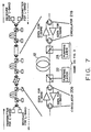
- FIG. 7 is a diagram showing another modified example of the third embodiment shown in FIG. 5.
- FIG. 7 shows a configuration in which circulators are provided in place of the WDM couplers of FIG. 5.
- AC-band optical signal is transmitted in the direction of the solid arrow and an L-band optical signal is transmitted in the direction of the dotted arrow.
- a C-band optical signal from the C-band transmitter enters the C-band EDFA via a circulator 20b for amplification.
- the amplified C-band optical signal then enters the circulator 20b again for continuous propagation over the transmission-path optical fiber 12.
- the C-band optical signal is subjected to distributed amplification by the pumping light from the pumping laser 23 based on the Raman amplifying action.
- the C-band optical signal thus processed is similarly amplified by the C-band EDFA via a circulator 21b, and transmitted via the circulator 21b to be received by the C-band receiver.
- An L-band optical signal from the L-band transmitter is amplified by the L-band EDFA via the circulator 21b, and then enters the transmission-path optical fiber 12 via the circulator 21b.
- the L-band optical signal is Raman-amplified by the pumping light from the pumping laser 22, and then enters the circulator 20b.
- the L-band optical signal exits from the optical fiber 12 via the circulator 20b to be received by the L-band receiver.
- the C-band optical signal is separated from the L-band optical signal using circulators. Since circulators separate optical signals codirectionally with the optical signals, they can reduce the system performance degradation due to variations in wavelength characteristics better than multilayer thin film filters and WDM couplers that separate optical signals by wavelength.
- optical signals are Raman-amplified in the backward pumping configuration.
- a bidirectional optical wavelength division multiplexed transmission system can be constructed using distributed amplifiers, while suppressing the degradation of its transmission quality.
Landscapes
- Physics & Mathematics (AREA)
- Electromagnetism (AREA)
- Engineering & Computer Science (AREA)
- Computer Networks & Wireless Communication (AREA)
- Signal Processing (AREA)
- Optical Communication System (AREA)
- Optical Modulation, Optical Deflection, Nonlinear Optics, Optical Demodulation, Optical Logic Elements (AREA)
- Lasers (AREA)
- Bidirectional Digital Transmission (AREA)
Abstract
Description
Claims (7)
- An optical wavelength division multiplexed transmission system in a bidirectional optical wavelength division multiplexed transmission system for transmitting an upstream optical signal and a downstream optical signal along a single line,
said optical wavelength multiplexed transmission system comprising:transmitting means for setting the upstream optical signal to a first band and transmitting the upstream optical signal set to the first band, and setting the downstream optical signal to a second band which is different from the first band and transmitting the downstream optical signal set to the second band; anddistributed amplifier means (12) having a first pumping light source (14) for pumping only the upstream optical signal set to the first band, and a second pumping light source (10) for pumping only the downstream optical signal set to the second band. - The optical wavelength division multiplexed transmission system according to claim 1, wherein said distributed amplifier means (12) performs distributed Raman amplification.
- The optical wavelength division multiplexed transmission systemaccording to claim 1, wherein said first pumping light source (14) amplifies the upstream optical signal set to the first band through backward pumping, and said second pumping light source (10) amplifies the downstream optical signal set to the second band through backward pumping.
- The optical wavelength division multiplexed transmission system according to claim 1, wherein each of said first and second pumping light sources (10, 14) includes a plurality of light sources (10-1, 10-2, 14-1, 14-2), each of said plurality of light sources having a different wavelength.
- The optical wavelength division multiplexed transmission system according to claim 1, comprising:a wavelength-selective multiplexing/demultiplexing means (20,21), located at one or both ends of said distributed amplifier means (12), for separating the upstream and downstream optical signals from each other and combining the separated upstream and downstream optical signals with each other; anddiscrete amplifier means (EDFA) for amplifying each of the up stream and downstream optical signals respectively set to the first and second bands.
- The optical wavelength division multiplexed transmission system according to claim 1, comprising:multilayer thin film filter means (20a, 21a), located at one or both ends of said distributed amplifier means (20), for separating the upstream and downstream optical signals from each other and combining the separated upstream and downstream optical signals with each other; anddiscrete amplifier means (EDFA) for amplifying each of the upstream and downstream optical signals respectively set to the first and second bands.
- The optical wavelength division multiplexed transmission system according to claim 1, comprising:circulator means (20b, 21b), located at one or both ends of said distributed amplifier means (12), for separating the upstream and downstream optical signals from each other and combining the separated upstream and downstream optical signals with each other; anddiscrete amplifier (EDFA) for amplifying each of the upstream and downstream optical signals respectively set to the first and second bands.
Applications Claiming Priority (2)
| Application Number | Priority Date | Filing Date | Title |
|---|---|---|---|
| JP2000321666A JP2002135212A (en) | 2000-10-20 | 2000-10-20 | Optical wavelength division multiplexing transmission system capable of bidirectional transmission |
| JP2000321666 | 2000-10-20 |
Publications (2)
| Publication Number | Publication Date |
|---|---|
| EP1199823A2 true EP1199823A2 (en) | 2002-04-24 |
| EP1199823A3 EP1199823A3 (en) | 2004-03-17 |
Family
ID=18799746
Family Applications (1)
| Application Number | Title | Priority Date | Filing Date |
|---|---|---|---|
| EP01105407A Withdrawn EP1199823A3 (en) | 2000-10-20 | 2001-03-12 | Bidirectional wavelength division multiplexed optical transmission system |
Country Status (3)
| Country | Link |
|---|---|
| US (1) | US6941074B2 (en) |
| EP (1) | EP1199823A3 (en) |
| JP (1) | JP2002135212A (en) |
Cited By (1)
| Publication number | Priority date | Publication date | Assignee | Title |
|---|---|---|---|---|
| WO2003079583A1 (en) | 2002-03-15 | 2003-09-25 | Mitsubishi Denki Kabushiki Kaisha | One-core two-way optical transmission system |
Families Citing this family (25)
| Publication number | Priority date | Publication date | Assignee | Title |
|---|---|---|---|---|
| KR100325687B1 (en) * | 1999-12-21 | 2002-02-25 | 윤덕용 | A low-cost WDM source with an incoherent light injected Fabry-Perot semiconductor laser diode |
| JP3831227B2 (en) * | 2001-10-30 | 2006-10-11 | 三菱電機株式会社 | Single core bidirectional transmission equipment |
| KR100496710B1 (en) * | 2002-01-21 | 2005-06-28 | 노베라옵틱스코리아 주식회사 | Bi-directional wavelength-division-multiplexing passive optical network utilizing wavelength-locked light sources by injected incoherent light |
| KR100454887B1 (en) * | 2002-01-30 | 2004-11-06 | 한국과학기술원 | The wavelength-division multiplexed passive optical network apparatus |
| US7346280B1 (en) * | 2002-03-15 | 2008-03-18 | Cisco Technology, Inc. | Bi-directional long haul/ultra long haul optical communication link |
| US20040208585A1 (en) * | 2002-03-20 | 2004-10-21 | Sycamore Networks, Inc. | Systems and methods for minimizing signal power and providing reduced Raman pump depletion for WDM optical system |
| KR100515259B1 (en) * | 2002-05-03 | 2005-09-15 | 한국과학기술원 | Wavelength-tunable light source and wavelength-division multiplexed transmission system with the sources |
| JP4176527B2 (en) * | 2003-03-31 | 2008-11-05 | 富士通株式会社 | Raman amplifier and optical transmission system using the same |
| KR100955129B1 (en) * | 2003-05-30 | 2010-04-28 | 정보통신연구진흥원 | Implementation Method of Wavelength Division Multiplexing Passive Network Using Incoherent Wideband Light Source |
| US7593641B2 (en) * | 2003-11-10 | 2009-09-22 | Harris Corporation | System and method of free-space optical satellite communications |
| US7313157B2 (en) * | 2003-12-19 | 2007-12-25 | Novera Optics, Inc. | Integration of laser sources and detectors for a passive optical network |
| DE102004037549A1 (en) * | 2004-08-03 | 2006-03-16 | Deutsche Telekom Ag | Device for generating and modulating a high-frequency signal |
| KR100584350B1 (en) * | 2004-08-09 | 2006-05-26 | 삼성전자주식회사 | Broadband Optical Module and Passive Optical Subscriber Network Using the Same |
| DE102005028844B4 (en) * | 2005-06-22 | 2007-07-05 | Luk Lamellen Und Kupplungsbau Beteiligungs Kg | Method and device for controlling a non-self-locking coupling |
| KR100698766B1 (en) * | 2005-09-07 | 2007-03-23 | 한국과학기술원 | Obstacle location monitoring device for wavelength division multiplex passive optical subscriber network system and wavelength division multiplex passive optical subscriber network system having same |
| KR100785436B1 (en) * | 2005-09-20 | 2007-12-13 | 한국과학기술원 | Wavelength Division Multiple Passive Optical Subscriber Network Converging Broadcast Service and Communication Service |
| US8571410B2 (en) * | 2006-10-11 | 2013-10-29 | Novera Optics, Inc. | Mutual wavelength locking in WDM-PONS |
| US8055130B2 (en) * | 2008-01-03 | 2011-11-08 | Dowslake Microsystems Corp. | Optical transceiver amplifier |
| ES2388629B1 (en) * | 2009-05-22 | 2013-08-27 | Consejo Superior De Investigaciones Científicas (Csic) | SYSTEM FOR IMPROVING THE DYNAMIC RANGE AND REDUCTION OF THE UNCERTAINTY OF MEASUREMENT IN DISTRIBUTED SENSORS ON OPTICAL FIBER. |
| EP2375602B1 (en) * | 2010-04-03 | 2019-12-18 | ADVA Optical Networking SE | Optical network element and optical transmission system |
| JP5699760B2 (en) * | 2011-04-04 | 2015-04-15 | 富士通株式会社 | Optical amplification device, optical amplification device control method, optical receiving station, and optical transmission system |
| US8849119B2 (en) | 2012-02-09 | 2014-09-30 | Electronics And Telecommunications Research Institute | Wavelength-shifted bidirectional wavelength division multiplexing optical network |
| US8855494B2 (en) * | 2012-07-24 | 2014-10-07 | Verizon Patent And Licensing Inc. | Multi-band reconfigurable optical add-drop multiplexer (ROADM) system |
| EP2854310B1 (en) * | 2013-09-30 | 2017-07-12 | Alcatel Lucent | Optical line terminal for a passive optical wavelength division multiplex network |
| US10340649B2 (en) * | 2017-03-07 | 2019-07-02 | Nec Corporation | C-band and L band amplifier design with increased power efficiency and reduced complexity |
Family Cites Families (10)
| Publication number | Priority date | Publication date | Assignee | Title |
|---|---|---|---|---|
| US4373782A (en) * | 1980-06-03 | 1983-02-15 | Optical Coating Laboratory, Inc. | Non-polarizing thin film edge filter |
| US4699452A (en) * | 1985-10-28 | 1987-10-13 | American Telephone And Telegraph Company, At&T Bell Laboratories | Optical communications system comprising Raman amplification means |
| DE69224340T2 (en) | 1991-09-30 | 1998-06-04 | Nippon Electric Co | Two-way repeater with optical amplification |
| IL106766A (en) | 1992-08-28 | 1995-12-31 | Hughes Aircraft Co | Bi-directional optical fiber amplifier for missile guidance data link repeater |
| EP0590379B1 (en) | 1992-09-30 | 1997-07-02 | Siemens Aktiengesellschaft | Optical transmission device for the transmission of optical signals in wavelength division multiplexing on a plurality of adjacent optical carrier wavelengths |
| AU1296695A (en) | 1993-12-01 | 1995-06-19 | Williams Telecommunications Group, Inc. | Bidirectional optical amplifier |
| DE69637562D1 (en) * | 1995-03-20 | 2008-07-24 | Fujitsu Ltd | Method and device for optical signal processing |
| GB2327546A (en) * | 1997-07-18 | 1999-01-27 | Northern Telecom Ltd | Optical frequency channel assignment plan and filtering technique to support it |
| KR100259268B1 (en) * | 1997-09-30 | 2000-06-15 | 강병호 | Optical circulator and wavelength splitter of integrated optical amplifier for bidirectional communication |
| US6163636A (en) | 1999-01-19 | 2000-12-19 | Lucent Technologies Inc. | Optical communication system using multiple-order Raman amplifiers |
-
2000
- 2000-10-20 JP JP2000321666A patent/JP2002135212A/en active Pending
-
2001
- 2001-03-08 US US09/800,891 patent/US6941074B2/en not_active Expired - Lifetime
- 2001-03-12 EP EP01105407A patent/EP1199823A3/en not_active Withdrawn
Cited By (2)
| Publication number | Priority date | Publication date | Assignee | Title |
|---|---|---|---|---|
| WO2003079583A1 (en) | 2002-03-15 | 2003-09-25 | Mitsubishi Denki Kabushiki Kaisha | One-core two-way optical transmission system |
| EP1387510A4 (en) * | 2002-03-15 | 2006-10-25 | Mitsubishi Electric Corp | One-core two-way optical transmission system |
Also Published As
| Publication number | Publication date |
|---|---|
| JP2002135212A (en) | 2002-05-10 |
| EP1199823A3 (en) | 2004-03-17 |
| US6941074B2 (en) | 2005-09-06 |
| US20020051267A1 (en) | 2002-05-02 |
Similar Documents
| Publication | Publication Date | Title |
|---|---|---|
| US6941074B2 (en) | Bidirectionally transmittable optical wavelength division multiplexed transmission system | |
| US5563733A (en) | Optical fiber amplifier and optical fiber transmission system | |
| EP1248392B1 (en) | Optical amplifier device and bidirectional wavelength division multiplexing optical communication system using the same | |
| EP1263096B1 (en) | Improved wide band erbium-doped fiber amplifier (EDFA) | |
| US12597752B2 (en) | Gain equalization in C+L erbium-doped fiber amplifiers | |
| JP3779691B2 (en) | Broadband erbium-doped optical fiber amplifier and wavelength division multiplexing optical transmission system employing the same | |
| US7075709B2 (en) | Optical transmission system, optical repeater, and optical transmission method | |
| US7346280B1 (en) | Bi-directional long haul/ultra long haul optical communication link | |
| JP4798997B2 (en) | Method and apparatus for distributing pump energy from a single pump device to optical fibers located in different pairs of fibers | |
| US20020064340A1 (en) | Optical wavelength-multiplexing technique | |
| US6549315B1 (en) | Optical transmission system and optical amplifying apparatus, optical amplifying unit, and optical coupler for the same | |
| EP0943192B1 (en) | Method and apparatus for saturating an optical amplifier chain to prevent over amplification of a wavelength division multiplexed signal | |
| JP3745721B2 (en) | Dispersion compensation optical fiber amplifier | |
| WO2005004356A1 (en) | Optical fiber communication system using remote pumping | |
| US6441952B1 (en) | Apparatus and method for channel monitoring in a hybrid distributed Raman/EDFA optical amplifier | |
| US20170214483A1 (en) | Efficient optical signal amplification systems and methods | |
| JP2713396B2 (en) | Optical fiber amplifier and optical fiber transmission system | |
| US6456425B1 (en) | Method and apparatus to perform lumped raman amplification | |
| JPH1174595A (en) | Optical fiber amplifier | |
| US7145716B2 (en) | Multiple stage Raman optical amplifier | |
| JPH07245436A (en) | Dual wavelength band amplifier and wavelength multiplexing transmission apparatus using the same | |
| JP2001028569A (en) | Hybrid Raman amplifier | |
| US6567208B1 (en) | Amplification of a C-band and L-band of a optical signal using a common laser signal | |
| JP2026013597A (en) | Optical transmission device, optical transmission system, and optical transmission method | |
| JPH02282226A (en) | System for compensating optical branching loss |
Legal Events
| Date | Code | Title | Description |
|---|---|---|---|
| PUAI | Public reference made under article 153(3) epc to a published international application that has entered the european phase |
Free format text: ORIGINAL CODE: 0009012 |
|
| AK | Designated contracting states |
Kind code of ref document: A2 Designated state(s): AT BE CH CY DE DK ES FI FR GB GR IE IT LI LU MC NL PT SE TR |
|
| AX | Request for extension of the european patent |
Free format text: AL;LT;LV;MK;RO;SI |
|
| PUAL | Search report despatched |
Free format text: ORIGINAL CODE: 0009013 |
|
| AK | Designated contracting states |
Kind code of ref document: A3 Designated state(s): AT BE CH CY DE DK ES FI FR GB GR IE IT LI LU MC NL PT SE TR |
|
| AX | Request for extension of the european patent |
Extension state: AL LT LV MK RO SI |
|
| RIC1 | Information provided on ipc code assigned before grant |
Ipc: 7H 01S 3/30 B Ipc: 7H 04B 10/24 A |
|
| 17P | Request for examination filed |
Effective date: 20040423 |
|
| 17Q | First examination report despatched |
Effective date: 20040602 |
|
| GRAP | Despatch of communication of intention to grant a patent |
Free format text: ORIGINAL CODE: EPIDOSNIGR1 |
|
| AKX | Designation fees paid |
Designated state(s): DE FR GB |
|
| STAA | Information on the status of an ep patent application or granted ep patent |
Free format text: STATUS: THE APPLICATION IS DEEMED TO BE WITHDRAWN |
|
| 18D | Application deemed to be withdrawn |
Effective date: 20050301 |