Technical Field
The present invention relates to a method and apparatus for
recording multi-valued information on an optical information recording
medium that allows information to be recorded/reproduced optically, such as
an optical disk.
Background Art
In recent years, optical disks, optical cards, optical tapes, or the like
have been proposed and under development as media for recording
information optically. Of the above media, the optical disks have drawn
attention, on which information can be recorded/reproduced with large
capacity and high density.
One type of rewritable optical disks is a phase change optical disk.
The phase change optical disk includes a recording film that is changed to
be in the amorphous or crystalline state depending on thermal and cooling
conditions by a laser beam. The amorphous and crystalline states can be
reversed. The recording film has optical constants (refractive index and
extinction coefficient) that differ in the amorphous and crystalline states.
In the phase change optical disk, the two states are provided selectively on
the recording film according to information signals so that the resultant
optical change (a change in transmissivity or reflectivity) is used to
record/reproduce the information signals.
To obtain the two states, information signals are recorded in the
following manner. The recording film of an optical disk is irradiated with a
laser beam in pulse form (with a power level of P1) focused by an optical
head. When the temperature of the recording film is raised to exceed the
melting point, the molten portion is cooled rapidly with the passage of the
laser beam to form an amorphous mark. The power level P1 is called a
recording power. For irradiation of the recording film with a focused laser
beam (with a power level of P2, P2 < P1) having an intensity that increases
the recording film temperature to temperatures ranging from the
crystallization temperature to the melting point, the irradiated portion of
the recording film is crystallized. The power level P2 is called an erasing
power.
In this manner, a recording pattern, including a mark of the
amorphous area and a non-mark portion of the crystalline area (referred to
as a space) that correspond to the information signals, is formed on a track
of the optical disk. The information signal can be reproduced by utilizing a
difference in the optical characteristics between the crystalline and
amorphous areas.
Recently, a mark edge recording (also referred to as PWM recording)
system is often used instead of a mark position recording (also referred to as
PPM recording) system. In the mark position recording, information is
represented by only the mark position itself. On the other hand, in the
mark edge recording, it is represented by both the leading and trailing edges
of a mark. Thus, the latter has the advantage of improving the recording
linear density.
To achieve further improvement in the recording density, a
multi-value recording method has been proposed, in which information of
three or more values is recorded on a single mark. For example, JP 4
(1992) - 209319 A discloses a method for recording multi-valued information
by forming marks having different sizes with laser beam irradiation of at
least three power levels.
However, the conventional multi-value recording method described
above has a problem in that, particularly when used with the mark edge
recording, information cannot be reproduced accurately due to an increase
in the jitter of a reproduced signal. This is because the leading and trailing
edges of an area in the mark where a width of the mark is constant and a
space area where the width is zero (hereinafter, each of those areas is
referred to as a unit recording area) are not formed at the precise positions.
For example, when a unit recording area with a large mark width is
recorded according to multi-valued information, the recording power of a
laser beam is increased, causing an increase in energy applied to a recording
film. Since thermal diffusion in the recording film is isotropic substantially
on the disk plane, the length of the unit recording area tends to be longer
than a predetermined length. On the other hand, when a unit recording
area with a small mark width is recorded, the recording power of the laser
beam is reduced. Therefore, the length of the unit recording area tends to
be shorter than a predetermined length. As a result, the leading and
trailing edges of the unit recording area thus formed are shifted variously
from the predetermined positions depending on the width thereof, which
corresponds to a value of the multi-valued information. This prevents
accurate reproduction of information that is represented by each edge of a
unit recording area.
Disclosure of Invention
Therefore, with the foregoing in mind, it is an object of the present
invention to provide a method and apparatus for recording optical
information that can record multi-valued information with accuracy and
high density by setting the leading and trailing edges of a recording pulse
appropriately.
To achieve the above object, a first optical information recording
method of the present invention includes irradiating an optical information
recording medium with a laser beam to cause a change in the optical
characteristics of a photosensitive recording film so that information is
recorded as a mark. An area in the mark where a width of the mark is
constant and a space area where the width is zero each are defined as a unit
recording area. Information is represented by at least three different
widths (i.e., three or more widths, including zero; the same is true in the
following) of the unit recording areas. The unit recording area having a
predetermined length and a predetermined width is formed by correcting
the leading and trailing edge positions of a recording pulse for recording the
unit recording area other than the space area in accordance with a width of
the unit recording area to be recorded.
This method can set both the recording power and the pulse
waveform of a laser beam according to the width of a unit recording area to
be recorded. Therefore, even if the unit recording area has any width, its
leading and trailing edges can be formed at predetermined positions,
resulting in accurate recording/reproduction of information.
In the first optical information recording method, it is preferable
that the unit recording area having a predetermined length and a
predetermined width is formed by correcting the leading and trailing edge
positions of the recording pulse in accordance with a combination of a width
and a length of the unit recording area to be recorded.
Moreover, it is preferable that the unit recording area having a
predetermined length and a predetermined width is formed by correcting
the leading edge position of the recording pulse in accordance with a
combination of a width of the unit recording area to be recorded, a length
thereof and a length of the preceding unit recording area and by correcting
the trailing edge position of the recording pulse in accordance with a
combination of a width of the unit recording area to be recorded, a length
thereof and a length of the next unit recording area.
These methods can set the waveform of a recording pulse according
to the length of a unit recording area to be recorded as well as the lengths of
the preceding and next unit recording areas, each having a different width.
Therefore, the leading and trailing edges of the unit recording area can be
formed more precisely at predetermined positions.
To achieve the above object, a second optical information recording
method of the present invention includes irradiating an optical information
recording medium with a laser beam to cause a change in the optical
characteristics of a photosensitive recording film so that information is
recorded as a mark. An area in the mark where a width of the mark is
constant and a space area where the width is zero each are defined as a unit
recording area. Information is represented by at least three different
widths of the unit recording areas. The unit recording area having a
predetermined length and a predetermined width is formed by correcting
the leading edge position of a recording pulse for recording the unit
recording area other than the space area in accordance with a combination
of a width of the unit recording area to be recorded and a width of the
preceding unit recording area and by correcting the trailing edge position of
the recording pulse in accordance with a combination of a width of the unit
recording area to be recorded and a width of the next unit recording area.
This method can set the edge positions of a recording pulse
according to the width of a unit recording area to be recorded as well as the
widths of the preceding and next unit recording areas. Therefore, even if
any combination of widths is provided, the leading and trailing edges of the
unit recording area can be formed at predetermined positions, resulting in
more accurate recording/reproduction of information.
In the second optical information recording method, it is preferable
that the unit recording area having a predetermined length and a
predetermined width is formed by correcting the leading edge position of the
recording pulse in accordance with a combination of a width of the unit
recording area to be recorded, a width of the preceding unit recording area
and a length of the unit recording area to be recorded and by correcting the
trailing edge position of the recording pulse in accordance with a
combination of a width of the unit recording area to be recorded, a width of
the next unit recording area and a length of the unit recording area to be
recorded.
Moreover, it is preferable that the unit recording area having a
predetermined length and a predetermined width is formed by correcting
the leading edge position of the recording pulse in accordance with a
combination of a width of the unit recording area to be recorded, a width of
the preceding unit recording area, a length of the unit recording area to be
recorded and a length of the preceding unit recording area and by correcting
the trailing edge position of the recording pulse in accordance with a
combination of a width of the unit recording area to be recorded, a width of
the next unit recording area, a length of the unit recording area to be
recorded and a length of the next unit recording area.
These methods can set the edge positions of a recording pulse
according to the length of a unit recording area to be recorded as well as the
lengths of the preceding and next unit recording areas, each having a
different width. Therefore, the leading and trailing edges of the unit
recording area can be formed more precisely at predetermined positions.
In the first and second optical information recording methods, it is
preferable that the amounts of correction of the leading and trailing edge
positions of the recording pulse are determined by recording and
reproducing a predetermined recording test pattern before recording the
information.
This method can determine the optimum amount of correction for an
optical information recording medium to be used in recording information.
Therefore, even if the optical information recording medium has recording
characteristic variations, information can be recorded accurately.
In the first and second optical information recording methods, it is
preferable that a predetermined reproduction test pattern is recorded on the
optical information recording medium so as to determine reproduction
conditions of the information by reproducing the reproduction test pattern
before reproducing the information.
This method can determine the optimum reproduction conditions for
an optical information recording medium to be used in recording
information. Therefore, information can be reproduced accurately even if
the shapes of marks are varied due to the recording characteristic variations
of the optical information recording medium.
The first and second optical information recording methods are
suitable particularly for the case where information is further represented
by the leading and trailing edges of the unit recording area as described
above.
In the first and second optical information recording methods, it is
preferable that the power of the laser beam is lowered to a bias level in the
portion between a first recording pulse for recording a first unit recording
area and a second recording pulse for recording a second unit recording area
when the first and second unit recording areas, each having a different
mark width other than zero, are recorded continuously as the unit recording
areas.
Conventionally, the power level of a laser beam is changed simply
according to the width of a mark to be formed without lowering to a bias
level. The above method is one aspect of the present invention, in which a
pulse is separated by temporarily lowering the level so that the edge
positions are corrected precisely.
It is preferable that the first and second optical information
recording methods further include selecting whether the information is
represented by a width of the unit recording area in accordance with the
type of information.
This method allows information to be represented by only edge
positions or the like instead of a mark width, e.g., when the information to
be recorded requires particularly low error rate. Therefore, the method can
select recording with high recording density or low error rate according to
information to be recorded, thus providing optimum recording based on the
information.
The present invention also provides an optical information recording
medium suitable for recording information with the above optical
information recording methods.
A first optical information recording medium of the present
invention includes a photosensitive recording film whose optical
characteristics are changed by laser beam irradiation. An area where a
width of a mark that is formed on the photosensitive recording film by the
laser beam irradiation is constant and a space area where the width is zero
each are defined as a unit recording area. An identifier for identifying
whether information is represented by a width of the unit recording area is
recorded previously on a predetermined area.
A recording/reproducing apparatus that uses this medium can
recognize easily whether information recorded on the medium is
represented by the width of a unit recording area by reproducing the
identifier.
A second optical information recording medium of the present
invention includes a photosensitive recording film whose optical
characteristics are changed by laser beam irradiation. An area where a
width of a mark that is formed on the photosensitive recording film by the
laser beam irradiation is constant and a space area where the width is zero
each are defined as a unit recording area. The amounts of correction of the
leading and trailing edge positions of a recording pulse for recording the
unit recording area other than the space area that are determined by a
width of the unit recording area to be recorded are recorded previously on a
predetermined area as information.
The use of this medium enables recording with the optimum amount
of correction that has been recorded thereon. Thus, even if the optical
information recording medium has recording characteristic variations,
information can be recorded accurately without determining the amount of
correction by recording/reproducing a test pattern.
To achieve the above object, a first optical information recording
apparatus of the present invention is an apparatus for recording
information on an optical information recording medium. The optical
information recording medium is irradiated with a laser beam having a
plurality of powers while switching the power of the laser beam to cause a
change in the optical characteristics of a photosensitive recording film so
that a mark is formed. An area in the mark where a width of the mark is
constant and a space area where the width is zero each are defined as a unit
recording area, and information is represented by at least three different
widths of the unit recording areas. The apparatus includes a modulation
means for modulating recording information to provide modulated
information, a multi-valued means for converting the modulated
information to multi-valued information, a recording pulse generation
means for generating a recording pulse based on the multi-valued
information, a recording power control means for controlling a recording
power in accordance with a width of the unit recording area to be recorded
that corresponds to the multi-valued information, an edge position
correction means for correcting leading and trailing edge positions of the
recording pulse in accordance with the width of the unit recording area to be
recorded, and a recording means for recording the information on the optical
information recording medium by irradiation of the laser beam based on the
recording power and the corrected recording pulse.
This apparatus can set both the recording power and the pulse
waveform of a laser beam according to the width of a unit recording area to
be recorded. Therefore, even if the unit recording area has any width, its
leading and trailing edges can be formed at predetermined positions,
resulting in accurate recording/reproduction of information.
In the first optical information recording apparatus, it is preferable
that the edge position correction means corrects the leading and trailing
edge positions of the recording pulse in accordance with a combination of a
width and a length of the unit recording area to be recorded.
Moreover, it is preferable that the edge position correction means
corrects the leading edge position of the recording pulse in accordance with
a combination of a width of the unit recording area to be recorded, a length
thereof and a length of the preceding unit recording area and the trailing
edge position of the recording pulse in accordance with a combination of a
width of the unit recording area to be recorded, a length thereof and a
length of the next unit recording area.
These apparatuses can set the waveform of a recording pulse
according to the length of a unit recording area to be recorded as well as the
lengths of the preceding and next unit recording areas, each having a
different width. Therefore, the leading and trailing edges of the unit
recording area can be formed more precisely at predetermined positions.
To achieve the above object, a second optical information recording
apparatus of the present invention is an apparatus for recording
information on an optical information recording medium. The optical
information recording medium is irradiates with a laser beam having a
plurality of powers while switching the power of the laser beam to cause a
change in the optical characteristics of a photosensitive recording film so
that a mark is formed. An area in the mark where a width of the mark is
constant and a space area where the width is zero each are defined as a unit
recording area, and information is represented by at least three different
widths of the unit recording areas. The apparatus includes a modulation
means for modulating recording information to provide modulated
information, a multi-valued means for converting the modulated
information to multi-valued information, a recording pulse generation
means for generating a recording pulse based on the multi-valued
information, a recording power control means for controlling a recording
power in accordance with a width of the unit recording area to be recorded
that corresponds to the multi-valued information, an edge position
correction means for correcting the leading edge position of the recording
pulse in accordance with a combination of a width of the unit recording area
to be recorded and a width of the preceding unit recording area and for
correcting the trailing edge position of the recording pulse in accordance
with a combination of a width of the unit recording area to be recorded and
a width of the next unit recording area, and a recording means for recording
the information on the optical information recording medium by irradiation
of the laser beam based on the recording power and the corrected recording
pulse.
This apparatus can set both the recording power and the pulse
waveform of a laser beam according to the width of a unit recording area to
be recorded as well as the widths of the preceding and next unit recording
areas. Therefore, even if the unit recording area has any width, its leading
and trailing edges can be formed at predetermined positions, resulting in
accurate recording/reproduction of information.
In the second optical information recording apparatus, it is
preferable that the edge position correction means corrects the leading edge
position of the recording pulse in accordance with a combination of a width
of the unit recording area to be recorded, a width of the preceding unit
recording area and a length of the unit recording area to be recorded, and
the trailing edge position of the recording pulse in accordance with a
combination of a width of the unit recording area to be recorded, a width of
the next unit recording area and a length of the unit recording area to be
recorded.
Moreover, it is preferable that the edge position correction means
corrects the leading edge position of the recording pulse in accordance with
a combination of a width of the unit recording area to be recorded, a width of
the preceding unit recording area, a length of the unit recording area to be
recorded and a length of the preceding unit recording area, and the trailing
edge position of the recording pulse in accordance with a combination of a
width of the recording unit area to be recorded, a width of the next unit
recording area, a length of the unit recording area to be recorded and a
length of the next unit recording area.
These apparatuses can set the edge positions of a recording pulse
according to the length of a unit recording area to be recorded as well as the
lengths of the preceding and next unit recording areas, each having a
different width. Therefore, the leading and trailing edges of the unit
recording area can be formed more precisely at predetermined positions.
Brief Description of Drawings
FIG. 1 is a block diagram showing the configuration of an
embodiment of a recording apparatus of the present invention.
FIGS. 2(a) to 2(e) are signal waveform diagrams and a track state
diagram that illustrate a recording operation of an embodiment of a
recording method of the present invention:
FIG. 2(a) illustrates four-valued information; FIG. 2(b) is a waveform diagram of a recording pulse; FIG. 2(c) is a waveform diagram of a corrected recording pulse to be
input to a laser driving circuit; FIG. 2(d) is a waveform diagram illustrating a change in the
emission power of a laser beam; and FIG. 2(e) illustrates the recorded state of marks on a track.
FIGS. 3(a) to 3(d) are a track state diagram and signal waveform
diagrams that illustrate an example of operation for reproducing
information recorded according to the present invention:
FIG. 3(a) illustrates the recorded state of marks on a track; FIG. 3(b) is a waveform diagram of a reproduced signal; FIG. 3(c) is a waveform diagram of a four-valued signal; and FIG. 3(d) shows four-valued information.
FIGS. 4(a) to 4(d) are signal waveform diagrams and a track state
diagram that illustrate a conventional recording method:
FIG. 4(a) illustrates four-valued information; FIG. 4(b) is a waveform diagram of a recording pulse; FIG. 4(c) is a waveform diagram of a recording pulse to be input to a
laser driving circuit; FIG. 4(d) is a waveform diagram illustrating a change in the
emission power of a laser beam; and FIG. 4(e) illustrates the recorded state of marks on a track.
FIGS. 5(a) to 5(e) are signal waveform diagrams and a track state
diagram that illustrate a recording operation of another embodiment of a
recording method of the present invention:
FIG. 5(a) illustrates four-valued information; FIG. 5(b) is a waveform diagram of a recording pulse; FIG. 5(c) is a waveform diagram of a corrected recording pulse to be
input to a laser driving circuit; FIG. 5(d) is a waveform diagram illustrating a change in the
emission power of a laser beam; and FIG. 5(e) illustrates the recorded state of marks on a track.
FIGS. 6(a) to 6(e) are signal waveform diagrams and a track state
diagram that illustrate a recording operation of yet another embodiment of
a recording method of the present invention:
FIG. 6(a) illustrates four-valued information; FIG. 6(b) is a waveform diagram of a recording pulse; FIG. 6(c) is a waveform diagram of a corrected recording pulse to be
input to a laser driving circuit; FIG. 6(d) is a waveform diagram illustrating a change in the
emission power of a laser beam; and FIG. 6(e) illustrates the recorded state of marks on a track.
FIG. 7 shows the relationship between the recording power and the
reproduced signal amplitude of an optical disk.
Detailed Description of the Invention
Hereinafter, embodiments of the present invention will be described
with reference to the accompanying drawings.
FIG. 1 is a block diagram showing the schematic configuration of a
recording/reproducing apparatus (optical information recording apparatus)
of an embodiment of the present invention.
The recording/reproducing apparatus of this embodiment uses an
optical disk 1 to record/reproduce information. Examples of the optical disk
1 include a phase change optical disk, a magneto-optical disk, and a disk
employing dye as a recording layer. Alternatively, the master of a stamper
with a photoresist coating for producing a read-only disk may be used.
The recording/reproducing apparatus includes a spindle motor 2 and
an optical head 10: the spindle motor 2 rotates the optical disk 1; the optical
head 10 includes a laser source (not shown) and focuses a laser beam on the
desired portion of the optical disk 1. The whole operation of the
recording/reproducing apparatus is controlled by a system control circuit 3.
The recording/reproducing apparatus includes a modulation circuit 4,
a multi-valued circuit 5, a recording pulse generation circuit 6, and an edge
position correction circuit 7 as a recording means. The modulation circuit 4
modulates recording information according to a predetermined modulation
rule to provide modulated information. The multi-valued circuit 5
generates multi-valued information according to the modulated information.
The recording pulse generation circuit 6 generates a recording pulse
according to the multi-valued information. The edge position correction
circuit 7 corrects the edge positions of the recording pulse. The
recording/reproducing apparatus further includes a power control circuit 9
that sets the power of the laser beam based on the multi-valued information.
Moreover, it is provided with a laser driving circuit 8 that modulates the
current for driving the laser source in the optical head 10 according to a
recording pulse output from the edge position correction circuit 7 and a
control signal from the power control circuit 9.
The recording/reproducing apparatus includes a reproduced signal
processing circuit 11, a multi-valued information generation circuit 12, and
a demodulation circuit 13 as a reproduction means for reproducing
information from the optical disk 1. The reproduced signal processing
circuit 11 performs waveform processing (such as equalizing) of a
reproduced signal based on the reflected light from the optical disk 1. The
multi-valued information generation circuit 12 generates four-valued
information from the reproduced signal. The demodulation circuit 13
demodulates reproduced information from the multi-valued information.
Next, the operation of the recording/reproducing apparatus of this
embodiment will be described with reference to signal waveform diagrams
and track state diagrams in FIGS. 2 and 3. FIG. 2 corresponds to the
operation for recording four-valued information, and FIG. 3 corresponds to
the operation for reproducing four-valued information.
For recording, first, the system control circuit 3 rotates the spindle
motor 2 so that the optical head 10 seeks a predetermined track on the
optical disk 1, and thus the system control circuit 3 determines a set value
of recording power in the power control circuit 9. Then, the system control
circuit 3 generates recording information based on data from a host
processor and sends it to the modulation circuit 4. The modulation circuit
4 transmits modulated information to the multi-valued circuit 5. The
multi-valued circuit 5 outputs four-valued information as shown in FIG. 2(a)
to each of the recording pulse generation circuit 6, the edge position
correction circuit 7, and the power control circuit 9.
The recording pulse generation circuit 6 generates a recording pulse
as shown in FIG. 2(b) based on the four-valued information. The recording
pulse may be produced with two-bit signals (i.e., two binary information
signals).
The recording
pulse generation circuit 6 transmits the recording
pulse to the edge position correction circuit 7. According to the four-valued
information from the
multi-valued circuit 5, the edge position correction
circuit 7 corrects the waveform of the recording pulse transmitted from the
recording pulse generation circuit as shown in FIG. 2(c). The amount of
correction (Δ
1F, Δ
1L, Δ
2F, Δ
2L, Δ
3F, Δ
3L) is registered on a memory within the
edge position correction circuit 7 as information shown in Tables 1 and 2.
The recording pulse waveform is corrected by referring to the memory. For
example, when the four-valued information is "3", the leading edge of the
recording pulse is delayed by Δ
3F and the trailing edge is advanced by Δ
3L.
When the four-valued information is "2" or "1", both edges are corrected in
the same manner, respectively. When the four-valued information is "0", it
corresponds to a space (i.e., a non-mark portion) in this embodiment, where
no recording pulse is present that requires edge correction. Therefore, the
recording pulse is not corrected.
| Four-valued information | Amount of correction of a leading edge |
| "0" | - |
| "1" | Δ1F |
| "2" | Δ2F |
| "3" | Δ3F |
| Four-valued information | Amount of correction of a trailing edge |
| "0" | - |
| "1" | Δ1L |
| "2" | Δ2L |
| "3" | Δ3L |
The power control circuit 9 determines a recording power of a laser
beam based on the four-valued information. In this embodiment, the
four-valued information is related to the recording power, as shown in Table
3.
For example, when information is recorded on a phase change
optical disk with the same recording pulse width, the relationship between
the recording power and the reproduced signal amplitude is such as to be
shown in FIG. 7, and the width of a mark is increased with increasing
reproduced signal amplitude. Therefore, the recording powers Pp1, Pp2, and
Pp3 can be selected so as to differ in reproduced signal amplitude, as
indicated by the three points of A1, A2, and A3 in FIG. 7.
The laser driving circuit modulates the current for driving the laser
based on a control signal from the
power control circuit 9 and the recording
pulse whose edge positions have been corrected. Consequently, the laser
beam emitted has a waveform as shown in FIG. 2(d).
| Four-valued information | Recording power |
| "0" | - |
| "1" | Pp1 |
| "2" | Pp2 |
| "3" | Pp3 |
The optical head 10 performs a recording operation on a
predetermined track. Thus, as shown in FIG. 2(e), recording marks 202,
203 and unit recording areas 204, 205, 206, and 207, each having a
predetermined length based on the four-valued information, are formed on a
track 201. Since the width of a unit recording area is determined by a
recording power, each of the unit recording areas has a predetermined width
based on the four-valued information (i.e., the mark areas with widths of W1,
W2, and W3 and the space area with zero width).
For reproduction, the track 201, on which the unit recording areas
204, 205, 206, and 207 are formed as shown in FIG. 3(a), is irradiated with
reproduction power by the laser in the optical head 10. Then, a
photodetector in the optical head 10 receives the reflected light and converts
it to an electric signal. FIG. 3(b) shows the waveform of the reproduced
signal thus converted, indicating that the signal of levels corresponding to
the widths of the unit recording areas is reproduced. The reproduced
signal processing circuit 11 equalizes the reproduced signal waveform and
slices the signal levels, so that the reproduced signal is converted to a
four-valued signal (see FIG. 3(c)). This embodiment employs three slice
levels (i.e., S1, S2, and S3 in FIG. 3(b)) to detect the levels of four values.
The multi-valued information generation circuit 12 generates four-valued
information as shown in FIG. 3(d), and the demodulation circuit 13
demodulates reproduced information.
As described above, the reason why the leading and trailing edges of
a recording pulse are corrected according to the width of a unit recording
area to be recorded is that the length of the unit recording area is shifted
variously from a predetermined length to be recorded when the unit
recording areas with different widths are recorded.
Generally, a higher recording power is necessary to record the unit
recording area having a large width. Increased recording power causes an
increase in energy to be applied to the recording film. Therefore, the length
of the unit recording area tends to be longer than a predetermined length.
This phenomenon will be described below by illustrating a conventional
example.
FIGS. 4(a) to 4(e) show signal waveforms and the state of marks
recorded on a track in a conventional multi-value recording method and
correspond to FIGS. 2(a) to 2(e) of this embodiment, respectively.
In the conventional multi-value recording method, when four-valued
information as shown in FIG. 4(a) is recorded, a recording pulse (FIG. 4(b))
is not corrected by the four-valued information. Therefore, the laser beam
emitted has a waveform as shown in FIG. 4(d) and produces a recording
power Pp3 for the four-valued information of "3", resulting in large energy
application to the recording film of an optical disk. Thus, the length of
each recording mark 401, 402 becomes longer than a predetermined length,
as shown in FIG. 4(e). Specifically, elongations 407 and 408 appear at the
leading edge of a unit recording area 403 and the trailing edge of a unit
recording area 404, respectively; also, elongations 409 and 410 appear at
both edges of a unit recording area 406 that is separated by a unit recording
area (space area) 405.
Similarly, the leading and trailing edges elongate when the
four-valued information is "2". However, since the recording power Pp2 is
lower than Pp3, the tendency to elongation is reduced, compared with the
four-valued information of "3". When the four-valued information is "1",
the leading and trailing edges elongate as well. However, the tendency is
smaller than that for the four-valued information of "2" for the same reason.
As described above, the tendency of a unit recording area to elongate
differs depending on four-valued information (i.e., the width of a unit
recording area to be recorded). This leads to the deviation of a reproduced
signal from a predetermined timing during reproduction, which in turn
causes various timing deviations of the four-valued signal that is converted
from the reproduced signal. Consequently, jitter is increased, making
accurate reproduction of information impossible.
On the other hand, this embodiment corrects the leading and
trailing edges of a recording pulse so that the unit recording having a
predetermined length can be recorded. The amount of correction of each
edge is set so as to record the unit recording area with a predetermined
length. Since high power recording generally tends to increase the length
of a unit recording area, the amount of correction of a recording pulse for
high power recording is larger than that for low power recording.
As described above, this embodiment corrects the leading and
trailing edges of a recording pulse according to the width of a unit recording
area to be recorded (i.e., four-valued information). Thus, even if the unit
recording area has any width, its edges can be formed at the precise
positions. Therefore, this embodiment has a special effect of recording and
reproducing multi-valued information accurately.
Also, this embodiment performs the above correction in the following
manner: when the unit recording areas 204 and 205, each having a different
mark width other than zero, are recorded continuously as shown in FIG. 2,
the power of a laser beam is lowered to a bias level of Pb in the portion
between a recording pulse for recording the unit recording area 204 and that
for the unit recording area 205.
In this embodiment, the waveform of a recording pulse is corrected
according to the width of a unit recording area to be recorded. It is
preferred to correct the recording pulse waveform as follows.
The first method is such that the recording pulse waveform is
corrected according to the length of a unit recording area to be recorded, in
addition to the width thereof. Generally, the length of a unit recording area
tends to be longer than a predetermined length because the amount of heat
accumulated increases with irradiation time even under the same recording
power. Thus, the correction according to not only the width but also the
length of a unit recording area enables more precise formation of the edges.
The second method is such that the leading and trailing edge
positions of a recording pulse are corrected respectively by combining the
width of a unit recording area to be recorded with both a width of the
preceding unit recording area and a width of the next unit recording area.
Considering the mutual influence of the adjacent unit recording areas
enables more precise formation of the edges. Here, the second method will
be described.
The amount of correction in this case is registered on a memory
within the edge position correction circuit 7 in FIG. 1 as information shown
in Tables 4 and 5. The leading and trailing edges of a recording pulse are
corrected by referring to the memory. The same correction is made when
the second information has different combinations. FIGS. 5(a) to 5(e) show
signal waveforms and the state of marks recorded on a track in a
multi-value recording method of this embodiment and correspond to FIGS.
2(a) to 2(e), respectively. In FIG. 5, e.g., when four-valued information to
be recorded is "3" and the preceding information is "0", the leading edge of a
recording pulse is delayed by Δ03F. When the four-valued information to be
recorded is "3" and the next information is "2", the trailing edge is advanced
by Δ32L.
In this manner, recording marks 501 and 502, each having a
predetermined length, are formed on a
track 201, which enables precise
formation of unit recording areas 503 (with a width of W
3), 504 (with a
width of W
2), 505 (with zero width) and 506 (with a width of W
1).
| Amount of correction of a leading edge |
| | Four-valued information |
| | "0" | "1" | "2" | "3" |
| The preceding four-valued information | "0" | - | Δ01F | Δ02F | Δ03F |
| "1" | - | Δ11F | Δ12F | Δ13F |
| "2" | - | Δ21F | Δ22F | Δ23F |
| "3" | - | Δ31F | Δ32F | Δ33F |
| Amount of correction of a trailing edge |
| | Four-valued information |
| | "0" | "1" | "2" | "3" |
| The next four-valued information | "0" | - | Δ10L | Δ20L | Δ30L |
| "1" | - | Δ11L | Δ21L | Δ31L |
| "2" | - | Δ12L | Δ22L | Δ32L |
| "3" | - | Δ13L | Δ23L | Δ33L |
The above operation can correct the variation in thermal
interference resulting from various differences in widths of the preceding
and next unit recording areas. Therefore, the unit recording area can be
recorded at more precise edge positions. In this case, the amount of
correction is increased with increasing width of a unit recording area to be
recorded (e.g., Δ01F < Δ02F < Δ03F holds in the first row of Table 4).
Moreover, it is preferred to use the above method with the following
method: the leading and trailing edges of a recording pulse are corrected
according to the length of a unit recording area as well as the lengths of the
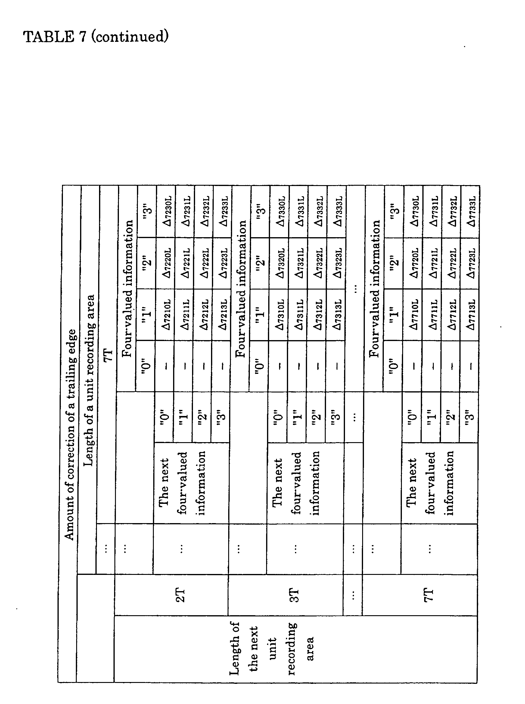
preceding and next unit recording areas. The amount of correction in this
case is registered on a memory within the edge position correction circuit 7
in FIG. 1 as information shown in Tables 6 and 7. The leading and trailing
edges of a recording pulse are corrected by referring to the memory. The
same correction is made when the second information has different
combinations. Tables 6 and 7 show a modulation system in which the
length of a unit recording area can range from 2T to 7T (T indicates a clock
cycle).
FIGS. 6(a) to 6(e) show signal waveforms and the state of marks
recorded on a track in a multi-value recording method of this embodiment
and correspond to FIG. 2(a) to 2(e), respectively. In FIG. 6, e.g., when
four-valued information to be recorded is "3", the preceding information is
"0", the length of a unit recording area to be recorded is 3T and the length of
the preceding unit recording area is 5T, the leading edge of a recording pulse
is delayed by Δ5303F. When the four-valued information to be recorded is "3",
the next information is "2", the length of the unit recording area to be
recorded is 3T and the length of the next unit recording area is 2T, the
trailing edge is advanced by Δ3232L.
The above operation can correct the variation in thermal
interference resulting from various differences in lengths of a unit recording
area itself and the preceding and next unit recording areas. Therefore,
marks can be recorded at more precise edge positions.
The embodiment shown in FIG. 6 also allows recording marks 601
and 602, each having a predetermined length, to be formed on a track 201,
which enables precise formation of unit recording areas 603 (with a width of
W3), 604 (with a width of W2), 605 (with zero width) and 606 (with a width
of W1).
In an optical information recording method of this embodiment, it is
preferable that prior to recording information, the amount of correction of
the leading and trailing edge positions of a recording pulse is determined by
recording and reproducing a predetermined recording test pattern. This
method can determine the optimum amount of correction for an optical
information recording medium to be used in recording information.
Therefore, even if the optical information recording medium has recording
characteristic variations, information can be recorded accurately.
In an optical information recording method of this embodiment, it is
preferable that prior to reproducing information, reproduction conditions for
the information are determined by reproducing a predetermined
reproduction test pattern recorded on the optical information recording
medium. This method can determine the optimum reproduction conditions
(such as equalizer characteristics) for an optical information recording
medium to be used in recording information. Therefore, information can be
reproduced accurately even if the shapes of marks are varied due to the
recording characteristic variations of the optical information recording
medium.
It is preferable that an optical information recording method of this
embodiment includes a process for selecting whether information is
represented by the width of a unit recording area according to the type of
information. This method allows information to be represented by only
mark edge positions when the information to be recorded requires a
particularly low error rate. Therefore, the method can select recording
with high recording density or low error rate according to the information to
be recorded, thus providing optimum recording based on the information.
For an optical information recording medium on which information
is recorded with an optical information recording method of this
embodiment, it is preferable that an identifier for identifying whether
information is represented by the width of a unit recording area is recorded
on a predetermined area of the medium. A recording/reproducing
apparatus that uses this medium can recognize easily whether information
recorded on the medium is represented by the width of a unit recording area
by reproducing the identifier.
For an optical information recording medium on which information
is recorded with an optical information recording method of this
embodiment, it is preferable that the amount of correction of the leading
and trailing edge positions of a recording pulse is recorded previously on a
predetermined area of the medium as information. The use of this medium
enables recording with the optimum amount of correction that has been
recorded thereon. Thus, even if the optical information recording medium
has recording characteristic variations, information can be recorded
accurately without determining the amount of correction by
recording/reproducing a test pattern.
A material for the optical disk is not limited to that described above,
and the above method can be applied to any media, as long as they have
optical characteristics that differ in the recording mark and non-mark
portions, such as made of a magneto-optical material, dye material, or the
like. The number of values that information has after conversion, the
above recording power, modulation system, length and position of each pulse,
or the like are not limited to those mentioned in the present embodiments; it
should be noted that the invention can set these elements appropriately
according to recording conditions or media. For example, in the above
embodiments, each of the unit recording areas is recorded with a single
recording pulse. However, the recording pulse may be composed of a
multipulse.
Industrial Applicability
As described above, the present invention selects at least one
appropriate factor from the widths and lengths of a unit recording area to be
recorded and the preceding and next unit recording areas, and corrects the
leading and/or trailing edge positions of a recording pulse according to the
factor (when a plurality of factors are selected, a combination of those
factors is used). The present invention can provide a special effect of
recording and reproducing multi-valued information accurately with the
position correction. In view of such effect, it is obvious that the present
invention is very useful in the field of optical information recording.