EP1199676A1 - Multi-level printing process reducing aliasing - Google Patents
Multi-level printing process reducing aliasing Download PDFInfo
- Publication number
- EP1199676A1 EP1199676A1 EP00203620A EP00203620A EP1199676A1 EP 1199676 A1 EP1199676 A1 EP 1199676A1 EP 00203620 A EP00203620 A EP 00203620A EP 00203620 A EP00203620 A EP 00203620A EP 1199676 A1 EP1199676 A1 EP 1199676A1
- Authority
- EP
- European Patent Office
- Prior art keywords
- resolution
- level
- bitmap
- pixels
- low
- Prior art date
- Legal status (The legal status is an assumption and is not a legal conclusion. Google has not performed a legal analysis and makes no representation as to the accuracy of the status listed.)
- Granted
Links
Images


Classifications
-
- G—PHYSICS
- G06—COMPUTING OR CALCULATING; COUNTING
- G06K—GRAPHICAL DATA READING; PRESENTATION OF DATA; RECORD CARRIERS; HANDLING RECORD CARRIERS
- G06K15/00—Arrangements for producing a permanent visual presentation of the output data, e.g. computer output printers
- G06K15/02—Arrangements for producing a permanent visual presentation of the output data, e.g. computer output printers using printers
-
- G—PHYSICS
- G06—COMPUTING OR CALCULATING; COUNTING
- G06K—GRAPHICAL DATA READING; PRESENTATION OF DATA; RECORD CARRIERS; HANDLING RECORD CARRIERS
- G06K15/00—Arrangements for producing a permanent visual presentation of the output data, e.g. computer output printers
- G06K15/02—Arrangements for producing a permanent visual presentation of the output data, e.g. computer output printers using printers
- G06K15/18—Conditioning data for presenting it to the physical printing elements
- G06K15/1835—Transforming generic data
- G06K15/1842—Geometric transformations, e.g. on raster data
- G06K15/1843—Changing size or raster resolution
-
- G—PHYSICS
- G06—COMPUTING OR CALCULATING; COUNTING
- G06K—GRAPHICAL DATA READING; PRESENTATION OF DATA; RECORD CARRIERS; HANDLING RECORD CARRIERS
- G06K15/00—Arrangements for producing a permanent visual presentation of the output data, e.g. computer output printers
- G06K15/02—Arrangements for producing a permanent visual presentation of the output data, e.g. computer output printers using printers
- G06K15/18—Conditioning data for presenting it to the physical printing elements
- G06K15/1835—Transforming generic data
- G06K15/1844—Anti-aliasing raster data
Definitions
- This invention relates to systems and procedures for printing documents.
- These documents can contain all types of visual information, such as text, graphics, images, etc, further commonly referred to as "image"
- This problem can be cured in two ways. The first one is to increase the spatial resolution of the recording device. This is often a technically difficult and costly solution.
- a second approach, and this is the approach to which the present invention relates, is to trade spatial resolution with tonal resolution in order to improve the visual quality. This approach is common for font rendering on computer displays. Here black pixels are surrounded by grey pixels. This results in visual smoothing of the edges, rendering the edges in a way more pleasing to the human eye.
- a procedure will be disclosed that creates multi-level gradation data from an abstract page description to achieve a similar result.
- Most documents to be printed contain a mixture of text, graphics and images and are given in the form of an page description. These documents may be PDF documents, PostScriptTM files, MS-OfficeTM documents and so on.
- spatial resolution and tonal resolution are to some extent interchangeable and that lack of spatial resolution can be compensated by improved tonal resolution.
- the use of multiple gradation levels enhances the tonal resolution in portions of the document where the data is highly discretised, such as text, drawings, etc. This technique requires that the recording engine has a means of rendering more than two different levels of grey or some other colour, i.e. more than 0%ink and 100%ink.
- An image as referred to hereinafter can be anything on a document such as text, graphics, images, etc.
- the page data describes the layout and content of the page to be reproduced, this data can be supplied in various formats.
- Rendering an image is the process of reproducing the image or document on a medium or on a display screen.
- the output bitmap is a bitmap which is sent to the printer for rendering of the image by the printer.
- the resolution of an image is the number of pixels used to represent a linear size of the image. For a physical representation of an image this is expressed as the number of pixels or dots per unit of length, e.g. 16 dots/mm or 400 dots/inch(dpi).
- the resolution can be defined as the physical resolution if the image would be rendered on a certain size.
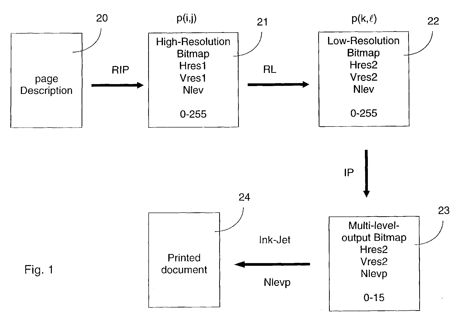
- Fig. 1 the page description 20 to be printed is processed by a Raster Image Processor (RIP) to produce high-resolution multi-level bitmap data 21 at a horizontal resolution Hres1, a vertical resolution Vres1, and a number of gradation levels Nlev.
- a resolution-lowering (RL) procedure converts the high-resolution multi-level bitmap data 21 to low-resolution multi-level bitmap data 22 from horizontal resolution Hres1 to Hres2 and from vertical resolution Vres1 to Vres2, where Hres1 ⁇ Hres2 and Vres1 ⁇ Vres2 and Hres2 xVres2 ⁇ Hres1 x Vres1.
- Hres2 and Vres2 correspond preferably to the horizontal and vertical spatial resolution of the printer by which the document will be printed.
- An image-processing (IP) step reduces the number of gradation levels from Nlev to Nlevp thereby converting the low resolution multi-level bitmap 22 to a low-gradation low-resolution output bitmap 23.
- Nlevp is preferebly the number of levels that can be printed with one single ink on a single pixel or microdot.
- a microdot is the smallest addressable unit on the substrate to be printed by the output device or printer.
- the multi-level output bitmap 23 is then sent to the printer for printing.
- Most documents to be printed contain a mixture of text, graphics and images and are given in the form of a page description 20.
- the page description 20 is device independent.
- To print the document the page description 20 has to be converted to a device dependent bitmap 23.
- the required number of pixels in the output bitmap 23 depends on the output resolution of the output device.
- the required number of levels for each pixel in that output bitmap 23 depends on the tone level capability of the output device.
- Such an output bitmap is preferably provided for each colour used to print out the document.
- the first step of a printing procedure according to the current invention is carried out by a RIP that transforms the page description 20 into a high-resolution multi-level bitmap 21 or rasterised data. This is done e.g.
- the horizontal and vertical size Hsize and Vsize are also specified and determine the number of pixels Hnpix1 and Vnpix1 in horizontal and vertical direction.
- the spatial resolution Hres and Vres for a continuous tone image may be expressed in pixels per millimetre.
- the spatial resolution Hres and Vres for a printing device is also expressed in pixels per millimetre, or sometimes (micro)dots per inch.
- the inkjet device can address per linear millimetre twelve microdots.
- mm 2 a total of 144 microdots can be addressed individually.
- the spatial resolution of the high-resolution bitmap 21 is eight times higher than that of the printing device.
- Hres1 may take the value of 96 microdots per mm. If the size of the printed image is known, e.g.
- Hnpix1 Hsize x Hres1
- Vnpix1 Vsize x Vres1.
- the Nlev different gradation levels are preferably represented in the interval [0.0, 1.0] by the numbers 0.0, 1.0/(Nlev-1), 2.0/(Nlev-1),..., 1.0.
- Hf x Vf pixels in the high-resolution (hi-res) bitmap 21 are mapped onto a single multi-level microdot.
- the hi-res bitmap 21 may be grouped in blocks of Hf x Vf pixels. Each block is mapped onto a pixel in the low-resolution (lo-res) bitmap 22 by the RL procedure.
- Nlevp is preferably the number of gradation levels of the output device. This has the following advantage :
- the reduction factors are chosen as to comply the conditions set by the above equation.
- the number of achieved density levels thus determines the used reduction factors.
- a few possible combinations for Nlevp, Hf and Vf that achieve the above equation are listed in the table 1 below. Choices for Hf and Vf combining with to specific Nlevp values. Nlevp Hf Vf 3 2 1 1 2 4 3 1 1 3 5 4 1 1 4 2 2 6 5 1 1 5 7 6 1 3 2 2 3 1 6 8 7 1 1 7 16 15 1 5 3 3 5 1 15
- the block of pixels from the hi-res bitmap 21 corresponding to a pixel p( k ,l) in the lo-res bitmap 22 is denoted by B(p). It is convenient to identify the pixel p( k ,l) in the lo-res bitmap with the centre of its block B(p) in the hi-res bitmap.
- the gradation level for the pixel p( k ,l) in the lo-res bitmap 22 is calculated from the pixel values in its corresponding block B(p).
- the gradation level Lp( k ,l) for the pixel p( k ,l) is taken equal to the average of the gradation levels of the pixels in B(p) or equal to the gradation level closest to this mean value.
- the hi-res bitmap 21 is converted to the lo-res bitmap 22, which has lower spatial resolution.
- the hi-res bitmap 21 will only contain levels 0 and 1, but the lo-res bitmap 22 will contain also other grey levels in the range 0.0, 1.0/(Nlev-1), 2.0/(Nlev-1), ..., 1.0.
- the font edges will appear softer after this operation.
- this operation combines local averaging and subsampling, and that the local averaging operation can be replaced by other filtering methods, linear or non-linear. This is especially advantageous if the hi-res bitmap 21 contains continuous tone data values, i.e. values within the interval [0.0, 1.0].
- a linear filter e.g. a gaussian filter and allow the blocks to overlap.
- W represents a weight function.
- linear filtering or convolution is meant a mathematical operation that produces a weighted local average value L of the pixel values Lq in the hi-res block B(p) i.e.
- W is called the filter or convolution mask.
- ⁇ q-p ⁇ is equal to the distance between p and q.
- a non-linear function is also conceivable.
- An example of such a non-linear function is median filtering of the values of the block.
- Hf and Vf there is the possibility in the algorithm to choose Hf and Vf (see table 1).
- the first option will guarantee the vertical stems to remain balanced, while the latter option keeps the horizontal stems, e.g. in the letter 'E', balanced.
- the chosen low-pass filter involved in the above described resampling procedure can be larger in the horizontal direction than in the vertical direction or vice versa.
- the above resampling operation can be followed by an additional non-linear mapping from 0.0, 1.0/(Nlev-1), 2.0/(Nlev-1), ..., 1.0 to 0.0, 1.0/(Nlev-1), 2.0/(Nlev-1), ..., 1.0.
- This mapping can compensate for the fact that the multiple levels, which the printer is capable to produce, are not necessarily linearly related in luminance. For colour documents, it is not necessary to treat all bitmaps of the colour separation in the same way.
- the above outlined procedure can e.g. be applied to the bitmaps in the colour separation using different block sizes and number of levels for different bitmaps, only to the black component, etc.
- a third step in the printing process according to an embodiment of the current invention is an image-processing step that reduces the number of gradation levels from Nlev to Nlevp and which converts (IP) the lo-res high-gradation multi-level bitmap 22 into a lo-res output bitmap 23.
- Nlevp is preferably the number of levels that can be printed with one ink on a single pixel or microdot.
- IP multi-level screening procedure or multi-level error diffusion.
- multi-level error diffusion is multi-level Floyd-Steinberg error diffusion, an extension of the algorithm by Floyd and Steinberg, see FLOYD R W and STEINBERG L, An adaptive algorithm for spatial grey scale, Society for Information Display 1975 Symposium Digest of Technical Papers, 36-37 (1975).
- FLOYD R W and STEINBERG L An adaptive algorithm for spatial grey scale, Society for Information Display 1975 Symposium Digest of Technical Papers, 36-37 (1975).
- the image pixels are processed in a sequential way.
- a pixel value 25 in the range 0.0, 1.0/(Nlev-1), 2.0/(Nlev-1), ..., 1.0 is set to its nearest value for the output 26 in the range 0.0, 1.0/(Nlevp-1), 2.0/(Nlevp-1), ..., 1.0 by quantizer 27.
- the error made by this quantisation is calculated by the error calculation circuit 28 and is distributed over its neighbours 29, 30, 31, 32 that have not yet been processed.
- An alternative way to reduce the number of gradation levels is the use of binary or multi-level screening techniques instead of error diffusion. As shown in Fig.4 screening may be performed by defining a (preferably periodic) screen function S( k,l ) and adding this function to the pixel data level L( k ,l) that is to be screened. The result of this addition L( k ,l)+S( k ,l) is then thresholded by a constant function T to yield binary pixel values B( k ,l).
- S( k,l) preferably periodic
- the screening operation S( k ,l) is represented in only one dimension instead of two. This procedure can be extended to multi-level screening in the following way.
- N 4.
- N 3 (three levels 0, 1/2, 1, two screening functions S 1 ( k ,l), S 2 ( k ,l)).
- the fourth step is the printing of the output bitmap by a multi-level reproduction device such as an ink-jet printing head.
- Printing heads exist today that can deliver variable drop sizes of a single ink, thereby giving the opportunity to create multiple grey or colour levels.
- the XaarJet 500 printheads which are available in binary and greyscale versions are an example of these.
- the printhead specification includes a printing width of 70 mm with 500 nozzles, and a printing resolution of 180 dpi (7 dots/mm) or 360 dpi (14 dots/mm).
- the image processing procedures as outlined in the first three steps can be combined with a printing step by such a printhead to print out the obtained multi-level bitmap data.
- This technique may also be used in electrographic or electrophotographic printers having multi-level capabilities as described e.g. in EP 0 634 862.
- Fig. 7a-7c give an example of the effect of the different methods used in the process on a text sample.
- Fig. 7a depicts the text sample as it would be printed without making use of the present invention.
- the page data is converted to a lo-res bitmap and the text is merely printed by the low resolution printhead using binary microdots.
- the binary dots can only have minimum and maximum density. This gives an unfavourable result with dominant aliasing distortion.
- Fig. 7b gives the image obtained after the first step of the method, i.e. the page data is converted to a hi-res, multi-level bitmap.
- the hi-res bitmap has a resolution three times higher in the horizontal and the vertical direction.
- the microdots still show only two levels, i.e. the minimum and maximum density because the text in page data corresponds to a black text on a white background. This image exists only in an electronic form and can not be printed out by the low-res printhead.
- the bitmap is multi-level, the microdots only take the minimum and maximum density value.
- the multi-level bitmap is converted to a multi-level bitmap (Nlev levels) at the resolution of the printhead.
- the horizontal and vertical reduction factor is set to 3. This is not shown in a figure.
- the obtained lo-res, multi-level bitmap can be printed by the printhead resulting in the image of Fig. 7c.
- an optimum use is made of the printhead's multi-level capability in combination with the resolution of the printer. Due to this method a smoother image is obtained avoiding aliasing effects.
Landscapes
- Engineering & Computer Science (AREA)
- General Engineering & Computer Science (AREA)
- Physics & Mathematics (AREA)
- General Physics & Mathematics (AREA)
- Theoretical Computer Science (AREA)
- Image Processing (AREA)
- Editing Of Facsimile Originals (AREA)
- Facsimile Image Signal Circuits (AREA)
- Dot-Matrix Printers And Others (AREA)
- Color, Gradation (AREA)
Abstract
Description
- This invention relates to systems and procedures for printing documents. These documents can contain all types of visual information, such as text, graphics, images, etc, further commonly referred to as "image"
- A well-known problem that is common to all recording systems, that convert image data into discretised pixel information, is the occurrence of reconstruction errors, commonly called 'aliasing'. It results in jagged edges at lines or curves that are not aligned with the discrete pixel grid of the recording apparatus or printer.
This problem can be cured in two ways. The first one is to increase the spatial resolution of the recording device. This is often a technically difficult and costly solution.
A second approach, and this is the approach to which the present invention relates, is to trade spatial resolution with tonal resolution in order to improve the visual quality.
This approach is common for font rendering on computer displays. Here black pixels are surrounded by grey pixels. This results in visual smoothing of the edges, rendering the edges in a way more pleasing to the human eye.
A procedure will be disclosed that creates multi-level gradation data from an abstract page description to achieve a similar result. Most documents to be printed contain a mixture of text, graphics and images and are given in the form of an page description. These documents may be PDF documents, PostScript™ files, MS-Office™ documents and so on. We have found that spatial resolution and tonal resolution are to some extent interchangeable and that lack of spatial resolution can be compensated by improved tonal resolution. The use of multiple gradation levels enhances the tonal resolution in portions of the document where the data is highly discretised, such as text, drawings, etc.
This technique requires that the recording engine has a means of rendering more than two different levels of grey or some other colour, i.e. more than 0%ink and 100%ink. However most ink-jet and bubble-jet printing devices can only deliver fixed-size drops of ink making the printing of multi-level pixel data without reducing the spatial resolution impossible.
Solutions to this problem have been proposed in terms of using multiple inks of the same colour, but different density. We refer to the documents WO 96/12251,EP 0 850 767 A1 and US 5,966,507. A method of surrounding black pixels by grey pixels for use in a 3-level electrophotographic printer was disclosed inEP 0 082 281 A1. - Further developments in electrophotographic printing allow the pixel size to be adapted. Procedures to enhance the resolution in that way, working by comparing the neighbourhood of a pixel with pre-existing templates, are described in US 4,847,641, US 5,193,008 and US 5,134,495.
This invention however differs from the above approaches in that it combines a number of image processing steps, different from the ones described in the above-cited references, with a technology to record multiple gradation levels at a single pixel, with the same ink. - It is an object of the present invention to provide a printing process in which the visual quality of the obtained image is enhanced.
It is a further object to enable the softening of jagged edges at lines or curves that are not aligned with the discrete pixel grid of the recording apparatus or printer. - The above mentioned objects are realised by a method having the specific features set out in
claim 1. Specific features for preferred embodiments of the invention are set out in the dependent claims. These objects are also realised by a system having specific features of claim 11
The above objects are mainly released by combining: - a process for printing multiple gradation levels at a single pixel, with the same ink and
- a procedure for obtaining multi-level gradation data from an abstract page description of the document to be printed.
-
- An image as referred to hereinafter can be anything on a document such as text, graphics, images, etc...
The page data describes the layout and content of the page to be reproduced, this data can be supplied in various formats. - Rendering an image is the process of reproducing the image or document on a medium or on a display screen.
- A bitmap is typically a two-dimensional array of pixels. Each pixel represents a small square or rectangular portion of an image. In grey images, each pixel may be represented by one value e.g. in the range of 0-255. Such a bitmap is called a multi-level bitmap as every pixel in the bitmap may take one of several available density values or gradation levels.
In colour images, each pixel is typically represented by three or more colour components. For each colour component of each pixel a value is required. In a system with three colour components, where each colour pixel value is represented by 8 bits, each colour pixel may take 256 different values for each component. Consequently each pixel may take 2563 = 16,777,216 possible values.
Besides the three colour values, extra bitmap values can be calculated for the black colour component.
The output bitmap is a bitmap which is sent to the printer for rendering of the image by the printer.
The resolution of an image is the number of pixels used to represent a linear size of the image. For a physical representation of an image this is expressed as the number of pixels or dots per unit of length, e.g. 16 dots/mm or 400 dots/inch(dpi). For electronic image data, the resolution can be defined as the physical resolution if the image would be rendered on a certain size. -
- Figure 1
- shows various steps in a printing process according to the invention.
- Figure 2
- shows the subdivision of a high-
resolution bitmap 21 into blocks. - Figure 3
- illustrates multi-level error diffusion.
- Figure 4
- shows how a screening function S(k,ℓ) is superposed on the continuous tone pixel L(k,ℓ) data and is thresholded to get bi-level output B(k,ℓ).
- Figure 5
- shows multi-level screening using one screening function S(k,ℓ).
- Figure 6
- shows how three-level screening with two screening functions can be done.
- Figure 7
- shows the effect of the processing on text.
- Figure 7a
- shows the text printed without making use of the present invention.
- Figure 7b
- shows the text printed at higher resolution.
- Figure 7c
- shows the text after an anti-aliasing procedure according to the invention.
- According to Fig. 1 the
page description 20 to be printed is processed by a Raster Image Processor (RIP) to produce high-resolutionmulti-level bitmap data 21 at a horizontal resolution Hres1, a vertical resolution Vres1, and a number of gradation levels Nlev.
Then a resolution-lowering (RL) procedure converts the high-resolutionmulti-level bitmap data 21 to low-resolutionmulti-level bitmap data 22 from horizontal resolution Hres1 to Hres2 and from vertical resolution Vres1 to Vres2, where
Hres1 ≥ Hres2 and Vres1 ≥ Vres2 and Hres2 xVres2 < Hres1 x Vres1. Hres2 and Vres2 correspond preferably to the horizontal and vertical spatial resolution of the printer by which the document will be printed.
An image-processing (IP) step reduces the number of gradation levels from Nlev to Nlevp thereby converting the low resolutionmulti-level bitmap 22 to a low-gradation low-resolution output bitmap 23. Nlevp is preferebly the number of levels that can be printed with one single ink on a single pixel or microdot.
A microdot is the smallest addressable unit on the substrate to be printed by the output device or printer.
Themulti-level output bitmap 23 is then sent to the printer for printing. - Most documents to be printed contain a mixture of text, graphics and images and are given in the form of a
page description 20. Thepage description 20 is device independent. To print the document thepage description 20 has to be converted to a devicedependent bitmap 23. The required number of pixels in theoutput bitmap 23 depends on the output resolution of the output device. The required number of levels for each pixel in thatoutput bitmap 23 depends on the tone level capability of the output device. Such an output bitmap is preferably provided for each colour used to print out the document. The first step of a printing procedure according to the current invention is carried out by a RIP that transforms thepage description 20 into a high-resolutionmulti-level bitmap 21 or rasterised data.
This is done e.g. by Adobe's Configurable PostScript Interpreter (CPSI). Horizontal and vertical resolution Hres1 and Vres1 can be specified to the RIP as well as the number of gradation levels Nlev to be used. Typically we take Nlev=256. The horizontal and vertical size Hsize and Vsize are also specified and determine the number of pixels Hnpix1 and Vnpix1 in horizontal and vertical direction.
The spatial resolution Hres and Vres for a continuous tone image may be expressed in pixels per millimetre. The spatial resolution Hres and Vres for a printing device is also expressed in pixels per millimetre, or sometimes (micro)dots per inch. A typical value for the spatial resolution of an inkjet printer is Hres2=Vres2= 300 dpi (dots per inch) which corresponds to about 12 microdots per mm. This means that the inkjet device can address per linear millimetre twelve microdots. Thus per square mm (mm2) a total of 144 microdots can be addressed individually. According to a preferred embodiment of the invention, the spatial resolution of the high-resolution bitmap 21 is eight times higher than that of the printing device. As such, Hres1 may take the value of 96 microdots per mm.
If the size of the printed image is known, e.g. the horizontal size Hsize=12 mm and the vertical size Vsize=20 mm, then also the number of pixels Hnpix1 and lines Vnpix1 or microdots required to represent the image at a resolution of Hres1, Vres1 by a matrix may be computed by the equations. - The Nlev different gradation levels are preferably represented in the interval [0.0, 1.0] by the numbers 0.0, 1.0/(Nlev-1), 2.0/(Nlev-1),..., 1.0.
- The second step is a resolution-lowering procedure RL. It converts the high-
resolution bitmap data 21 from a first spatial resolution (Hres1,Vres1) and tonal resolution Nlev to a low-resolution bitmap 22 with second spatial resolution (Hres2,Vres2), the same tonal resolution Nlev and the same spatial dimensions Hsize2=Hsize1=Hsize and Vsize2=Vsize1=Vsize preferably in the following way.
Let Hf = Hres1/Hres2 and Vf = Vres1/Vres2 be integer numbers.
Hf is the horizontal reduction factor and Vf is the vertical reduction factor.
Let Hnpix2 = Hsize x Hres2, Vnpix2 = Vsize x Vres2.
As shown in Fig. 2 to achieve the reduction, Hf x Vf pixels in the high-resolution (hi-res)bitmap 21 are mapped onto a single multi-level microdot. When converting, the hi-res bitmap 21 may be grouped in blocks of Hf x Vf pixels. Each block is mapped onto a pixel in the low-resolution (lo-res)bitmap 22 by the RL procedure. Preferably Hf and Vf are selected such that Hf x Vf = Nlevp-1.
Nlevp is preferably the number of gradation levels of the output device. This has the following advantage : - When using reduction factors Hf and Vf, generally a rectangular area containing Hf x Vf pixels of the hi-
res bitmap 21 is transformed to one pixel in the lo-res bitmap 22. The original pixels of a hi-res text normally have only minimum or maximum value, i.e. the pixel is blank or it is filled "full density". Within the hi-res rectangular area the number of pixels which can be filled, is within therange
When Hf x Vf = Nlevp-1 the fill number of the pixels within the area can simply be converted into a density level of the lo-res pixel representing the rectangular area.
Preferably the reduction factors are chosen as to comply the conditions set by the above equation. The number of achieved density levels thus determines the used reduction factors.
A few possible combinations for Nlevp, Hf and Vf that achieve the above equation are listed in the table 1 below.Choices for Hf and Vf combining with to specific Nlevp values. Nlevp Hf Vf 3 2 1 1 2 4 3 1 1 3 5 4 1 1 4 2 2 6 5 1 1 5 7 6 1 3 2 2 3 1 6 8 7 1 1 7 16 15 1 5 3 3 5 1 15 - Indicating the pixels in the hi-
res bitmap 21 by p(i,j), with 0 ≤ i ≤ Hnpix1-1 and 0 ≤ j ≤ Vnpix1-1, all pixels p(i,j) for which
(i div Hf) = k
(j div Vf) = ℓ
for someinteger numbers 0 ≤ k ≤ Hnpix2-1 and 0 ≤ ℓ ≤ Vnpix2-1 are grouped in one block and will be mapped onto the pixel p(k,ℓ) in the lo-res bitmap 22. The operation (a div b) is the result of integer division of a by b.
10 The block of pixels from the hi-res bitmap 21 corresponding to a pixel p(k,ℓ) in the lo-res bitmap 22 is denoted by B(p). It is convenient to identify the pixel p(k,ℓ) in the lo-res bitmap with the centre of its block B(p) in the hi-res bitmap. The gradation level for the pixel p(k,ℓ) in the lo-res bitmap 22 is calculated from the pixel values in its corresponding block B(p). Preferably the gradation level Lp(k,ℓ) for the pixel p(k,ℓ) is taken equal to the average of the gradation levels of the pixels in B(p) or equal to the gradation level closest to this mean value.
In this way the hi-res bitmap 21 is converted to the lo-res bitmap 22, which has lower spatial resolution.
When the document consists e.g. out of pure black text fonts, the hi-res bitmap 21 will only containlevels res bitmap 22 will contain also other grey levels in the range 0.0, 1.0/(Nlev-1), 2.0/(Nlev-1), ..., 1.0.
The font edges will appear softer after this operation.
It is clear that this operation combines local averaging and subsampling, and that the local averaging operation can be replaced by other filtering methods, linear or non-linear. This is especially advantageous if the hi-res bitmap 21 contains continuous tone data values, i.e. values within the interval [0.0, 1.0].
Alternatively we may want to use a linear filter, e.g. a gaussian filter and allow the blocks to overlap. Let p represent the location of the lo-res pixel (the centre of B(p)) and q represent the location of a hi-res pixel in block B(p). W represents a weight function. By linear filtering or convolution is meant a mathematical operation that produces a weighted local average valueL of the pixel values Lq in the hi-res block B(p) i.e.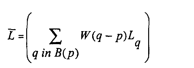
- Preferably for the weights W(q-p), 0 ≤ W(q-p)≤ 1.0 and Σ W(q-p)= 1.0 but W(q-p) may also take negative values. W is called the filter or convolution mask.
A gaussian filter is a linear filter for which the weights Wq have gaussian values e.g. W(q-p) = t.exp (-∥q-p∥2/s), with t and s scaling factors. ∥q-p∥ is equal to the distance between p and q.
Instead of taking a linear function to obtainL , a non-linear function is also conceivable. An example of such a non-linear function is median filtering of the values of the block. More detailed information can be found in "A simplified approach to image processing, Randy Crane, Prentice Hall, New Jersey (1997)".
In fact, these operations are all special cases of the more general procedure of resampling.
According to the sampling theory, to regain a continuous signal from its sampled version, it is advantageous to pass this signal through an ideal low-pass filter, to reconstruct the continuous signal exactly when this continuous signal is band-limited in frequency space. Since images are always limited in spatial extent, they can never really be band-limited in frequency space, but low-pass filtering nevertheless provides an approximation of the continuous signal. To resample a signal, the appropriate strategy is to first try to approximate the continuous signal and then sample this continuous signal.
The RL process described herein above amounts thus to low-pass filtering followed by sampling.
When the operation is viewed in this way, there is no need to restrict the method according to the current invention to the case where Hf = Hres1/Hres2 and Vf = Vres1/Vres2 are integer numbers and Hf x Vf = Nlevp-1.
The sampling operation can be interpreted as a geometric shrinking of the image wherein a pixel (i,j) is mapped onto (k,ℓ)=(i/Hf,j/Vf). But in general k and ℓ are not integer values.
To determine the pixel value for a pixel(k, ℓ) of the sampled image interpolation between the pixels lying close to (Hf*k,Vf*ℓ) in the hi-res image is advantageous. To this end nearest neighbour interpolation, bilinear interpolation, bicubic interpolation, etc.. may be used. These techniques are described in the book by "Crane" referred to before.
A possible draw-back of this procedure is the following. Most conversions from abstract page data to bitmap characters use so-called font hinting. This font hinting guarantees that vertical or horizontal lines within the same character and among different characters are all equally thick, e.g. all three stems in the letter 'm' are equally thick, and they are equally thick as the stems of the letter 'n'. The conservation of this property is not guaranteed by the above procedure. In practice however, this seems to be not of major importance, and the benefits of the current procedure outweigh this possible drawback.
Moreover, there is the possibility in the algorithm to choose Hf and Vf (see table 1). For Nlevp=4, one can choose Hf=3, Vf=1 or Hf=1, Vf=3. The first option will guarantee the vertical stems to remain balanced, while the latter option keeps the horizontal stems, e.g. in the letter 'E', balanced. Alternatively, the chosen low-pass filter involved in the above described resampling procedure can be larger in the horizontal direction than in the vertical direction or vice versa.
The above resampling operation can be followed by an additional non-linear mapping from 0.0, 1.0/(Nlev-1), 2.0/(Nlev-1), ..., 1.0 to 0.0, 1.0/(Nlev-1), 2.0/(Nlev-1), ..., 1.0. This mapping can compensate for the fact that the multiple levels, which the printer is capable to produce, are not necessarily linearly related in luminance.
For colour documents, it is not necessary to treat all bitmaps of the colour separation in the same way. The above outlined procedure can e.g. be applied to the bitmaps in the colour separation using different block sizes and number of levels for different bitmaps, only to the black component, etc. - A third step in the printing process according to an embodiment of the current invention is an image-processing step that reduces the number of gradation levels from Nlev to Nlevp and which converts (IP) the lo-res high-gradation
multi-level bitmap 22 into a lo-res output bitmap 23. Nlevp is preferably the number of levels that can be printed with one ink on a single pixel or microdot. For this conversion (IP) one can use a multi-level screening procedure or multi-level error diffusion.
An example of multi-level error diffusion is multi-level Floyd-Steinberg error diffusion, an extension of the algorithm by Floyd and Steinberg, see FLOYD R W and STEINBERG L, An adaptive algorithm for spatial grey scale, Society for Information Display 1975 Symposium Digest of Technical Papers, 36-37 (1975). In this algorithm the image pixels are processed in a sequential way. As shown in Fig.3 apixel value 25 in the range 0.0, 1.0/(Nlev-1), 2.0/(Nlev-1), ..., 1.0 is set to its nearest value for theoutput 26 in the range 0.0, 1.0/(Nlevp-1), 2.0/(Nlevp-1), ..., 1.0 byquantizer 27. The error made by this quantisation is calculated by theerror calculation circuit 28 and is distributed over itsneighbours
An alternative way to reduce the number of gradation levels is the use of binary or multi-level screening techniques instead of error diffusion.
As shown in Fig.4 screening may be performed by defining a (preferably periodic) screen function S(k,ℓ) and adding this function to the pixel data level L(k,ℓ) that is to be screened. The result of this addition L(k,ℓ)+S(k,ℓ) is then thresholded by a constant function T to yield binary pixel values B(k,ℓ). When e.g. both the screen function S(k,ℓ) and pixel data levels L(k,ℓ) take values in [0,1], the following binary value B(k,ℓ) may be assigned to the pixel (k,ℓ) :
This procedure can be extended to multi-level screening in the following way.
In Fig.5 the situation is shown for mapping continuous tone pixel data L(k,ℓ) (0 ≤ L(k,ℓ) ≤ 1) to 4-level data N(k,ℓ)= 0, 1/3, 2/3, 1 by using a screen function S(k,ℓ) (0 ≤ S(k,ℓ) ≤ 1)
N(k,ℓ) can be calculated as follows: let K ∈ { 0,1,2,...,N-1},
Alternatively, it is possible to use N-1 screening functions S1,...,SN-1, chosen such that for all pixels (k,ℓ)levels - The fourth step is the printing of the output bitmap by a multi-level reproduction device such as an ink-jet printing head. Printing heads exist today that can deliver variable drop sizes of a single ink, thereby giving the opportunity to create multiple grey or colour levels. The XaarJet 500 printheads, which are available in binary and greyscale versions are an example of these. The printhead specification includes a printing width of 70 mm with 500 nozzles, and a printing resolution of 180 dpi (7 dots/mm) or 360 dpi (14 dots/mm).
The image processing procedures as outlined in the first three steps can be combined with a printing step by such a printhead to print out the obtained multi-level bitmap data. This technique may also be used in electrographic or electrophotographic printers having multi-level capabilities as described e.g. inEP 0 634 862. - Fig. 7a-7c give an example of the effect of the different methods used in the process on a text sample.
Fig. 7a depicts the text sample as it would be printed without making use of the present invention. The page data is converted to a lo-res bitmap and the text is merely printed by the low resolution printhead using binary microdots. The binary dots can only have minimum and maximum density. This gives an unfavourable result with dominant aliasing distortion.
Fig. 7b gives the image obtained after the first step of the method, i.e. the page data is converted to a hi-res, multi-level bitmap. In this example the hi-res bitmap has a resolution three times higher in the horizontal and the vertical direction. The microdots still show only two levels, i.e. the minimum and maximum density because the text in page data corresponds to a black text on a white background. This image exists only in an electronic form and can not be printed out by the low-res printhead. Although the bitmap is multi-level, the microdots only take the minimum and maximum density value.
In the second step the multi-level bitmap is converted to a multi-level bitmap (Nlev levels) at the resolution of the printhead. The horizontal and vertical reduction factor is set to 3. This is not shown in a figure.
In the third step the number of levels of the multi-resolution bitmap is reduced to the number of levels (here Nlevp = 10 levels) which can be printed by the printhead. To obtain an easy conversion, the reduction factors Hf and Vf and Nlevp fulfil the requirements of Hf x Vf = Nlevp - 1 (3 x 3 = 10 - 1).
The obtained lo-res, multi-level bitmap can be printed by the printhead resulting in the image of Fig. 7c. As can be seen an optimum use is made of the printhead's multi-level capability in combination with the resolution of the printer. Due to this method a smoother image is obtained avoiding aliasing effects.
Claims (11)
- A method for rendering an image comprising the steps of :is characterised in that Hres1 ≥ Hres2 and Vres1 ≥ Vres2 and Hres2xVres2 < Hres1xVres1.converting page data (20) to a high-resolution multi-level bitmap (21), comprising pixels p(i,j), having a vertical resolution Vres1 and a horizontal resolution Hres1,converting the high-resolution multi-level bitmap (21) to a low-resolution multi-level bitmap (22) comprising pixels p(k,ℓ), having a vertical resolution Vres2 and a horizontal resolution Hres2,rendering the low-resolution multi-level bitmap (22) with a multi-level output device,
- The method according to claim 1 wherein said high-resolution multi-level bitmap (21) has Nlev gradation levels and said low-resolution multi-level bitmap (22) has Nlev gradation levels and wherein the step of rendering said low-resolution multi-level bitmap (22) comprises the steps of :processing the low-resolution multi-level bitmap (22) to reduce the number of gradation levels Nlev to a number of gradation levels Nlevp to obtain an low-gradation, low-resolution output bitmap (23) wherein Nlev > Nlevp;printing said output bitmap (23) on said output device.
- Method according to claim 2 comprising the steps ofdefining a horizontal reduction factor Hfselecting Nlevp such that Hf x Vf = Nlevp - 1
- Method according to claim 3 wherein the reduction factors Hf and Vf have integer values.
- Method according to any one of the preceding claims wherein the low-resolution multi-level bitmap (22) is a resampled version of the high-resolution multi-level bitmap (21).
- Method according to any one of the preceding claims wherein the gradation level of said pixel p(k,ℓ) is determined by a local average of the gradation levels of pixels p(i,j).
- Method according to any one of the preceding claims wherein the gradation level of said pixel p(k,ℓ) is determined by a weighted local average, using a linear filter function or convolution mask, of the gradation levels of pixels p(i,j).
- Method according to claims 1 to 5 wherein the gradation level of pixel p(k,ℓ) is determined by a non-linear filter function of the gradation levels of pixels p(i,j).
- A method for rendering a colour image from a plurality of colour bitmaps (21) wherein at least one colour bitmap (21) is treated by the method according to any one of the preceding claims.
- Method according to any one of the preceding claims wherein the multi-level output device is an inkjet printer.
- A system for rendering an image from page data (20) comprising :means for converting said page data (20) to a high-resolution multi-level bitmap (21) comprising pixels p(i,j) and having a vertical resolution Vres1 and a horizontal resolution Hres1,means for converting the high-resolution multi-level bitmap (21) to a low-resolution multi-level bitmap (22) comprising pixels p(k,ℓ), and having a vertical resolution Vres2, a horizontal resolution Hres2 wherein Hres1 ≥ Hres2 and Vres1 ≥ Vres2 and Hres2xVres2 < Hres1xVres1,multi-level output means for rendering the low-resolution multi-level bitmap (22).
Priority Applications (4)
| Application Number | Priority Date | Filing Date | Title |
|---|---|---|---|
| DE2000611904 DE60011904T2 (en) | 2000-10-17 | 2000-10-17 | Multi-color printing process to reduce aliasing noise |
| EP20000203620 EP1199676B1 (en) | 2000-10-17 | 2000-10-17 | Multi-level printing process reducing aliasing |
| US09/981,056 US6725779B2 (en) | 2000-10-17 | 2001-10-16 | Multi-level printing process reducing aliasing in graphics |
| JP2001318022A JP3900252B2 (en) | 2000-10-17 | 2001-10-16 | Multi-level printing method to reduce graphics aliasing |
Applications Claiming Priority (1)
| Application Number | Priority Date | Filing Date | Title |
|---|---|---|---|
| EP20000203620 EP1199676B1 (en) | 2000-10-17 | 2000-10-17 | Multi-level printing process reducing aliasing |
Publications (2)
| Publication Number | Publication Date |
|---|---|
| EP1199676A1 true EP1199676A1 (en) | 2002-04-24 |
| EP1199676B1 EP1199676B1 (en) | 2004-06-30 |
Family
ID=8172153
Family Applications (1)
| Application Number | Title | Priority Date | Filing Date |
|---|---|---|---|
| EP20000203620 Expired - Lifetime EP1199676B1 (en) | 2000-10-17 | 2000-10-17 | Multi-level printing process reducing aliasing |
Country Status (3)
| Country | Link |
|---|---|
| EP (1) | EP1199676B1 (en) |
| JP (1) | JP3900252B2 (en) |
| DE (1) | DE60011904T2 (en) |
Cited By (2)
| Publication number | Priority date | Publication date | Assignee | Title |
|---|---|---|---|---|
| US6725779B2 (en) | 2000-10-17 | 2004-04-27 | Agfa-Gevaert | Multi-level printing process reducing aliasing in graphics |
| EP1492331A3 (en) * | 2003-06-23 | 2007-09-05 | Xerox Corporation | Methods and apparatus for antialiasing using selective implementation of logical and averaging filter operations |
Citations (5)
| Publication number | Priority date | Publication date | Assignee | Title |
|---|---|---|---|---|
| EP0651557A1 (en) * | 1993-11-01 | 1995-05-03 | Xerox Corporation | Apparatus and method for arbitrary binary resolution conversion |
| US5455681A (en) * | 1992-11-16 | 1995-10-03 | Eastman Kodak Company | Low resolution grey level printing method from high resolution binary input file |
| GB2294427A (en) * | 1994-10-12 | 1996-05-01 | Canon Res Ct Europe Ltd | Anti-aliasing printer |
| EP0786757A1 (en) * | 1996-01-25 | 1997-07-30 | Adobe Systems Incorporated | Adjusting contrast in antialiasing |
| US5862257A (en) * | 1995-04-25 | 1999-01-19 | Fuji Xerox Co., Ltd. | Image processing apparatus and image forming apparatus |
-
2000
- 2000-10-17 EP EP20000203620 patent/EP1199676B1/en not_active Expired - Lifetime
- 2000-10-17 DE DE2000611904 patent/DE60011904T2/en not_active Expired - Fee Related
-
2001
- 2001-10-16 JP JP2001318022A patent/JP3900252B2/en not_active Expired - Fee Related
Patent Citations (5)
| Publication number | Priority date | Publication date | Assignee | Title |
|---|---|---|---|---|
| US5455681A (en) * | 1992-11-16 | 1995-10-03 | Eastman Kodak Company | Low resolution grey level printing method from high resolution binary input file |
| EP0651557A1 (en) * | 1993-11-01 | 1995-05-03 | Xerox Corporation | Apparatus and method for arbitrary binary resolution conversion |
| GB2294427A (en) * | 1994-10-12 | 1996-05-01 | Canon Res Ct Europe Ltd | Anti-aliasing printer |
| US5862257A (en) * | 1995-04-25 | 1999-01-19 | Fuji Xerox Co., Ltd. | Image processing apparatus and image forming apparatus |
| EP0786757A1 (en) * | 1996-01-25 | 1997-07-30 | Adobe Systems Incorporated | Adjusting contrast in antialiasing |
Cited By (2)
| Publication number | Priority date | Publication date | Assignee | Title |
|---|---|---|---|---|
| US6725779B2 (en) | 2000-10-17 | 2004-04-27 | Agfa-Gevaert | Multi-level printing process reducing aliasing in graphics |
| EP1492331A3 (en) * | 2003-06-23 | 2007-09-05 | Xerox Corporation | Methods and apparatus for antialiasing using selective implementation of logical and averaging filter operations |
Also Published As
| Publication number | Publication date |
|---|---|
| DE60011904D1 (en) | 2004-08-05 |
| EP1199676B1 (en) | 2004-06-30 |
| DE60011904T2 (en) | 2005-08-25 |
| JP3900252B2 (en) | 2007-04-04 |
| JP2002218227A (en) | 2002-08-02 |
Similar Documents
| Publication | Publication Date | Title |
|---|---|---|
| US6725779B2 (en) | Multi-level printing process reducing aliasing in graphics | |
| EP0707410B1 (en) | Improved adaptive filtering and thresholding arrangement for reducing graininess of images | |
| CA2132248C (en) | Apparatus and method for arbitrary binary resolution conversion | |
| US5949964A (en) | Method and apparatus for halftoning of images in a printer | |
| US5727137A (en) | Printer driver architecture for reducing band memory | |
| US5245678A (en) | Image conversion with lossy adaptive error diffusion | |
| JPH11331581A (en) | Method for optimizing rendition of tone and edge | |
| US5956470A (en) | Text quality enhancement via resolution enhancement technique based on separating jaggedness detection and filtering | |
| US20120113477A1 (en) | Laser print apparatus with dual half tones | |
| US20080260284A1 (en) | Edge contrast adjustment filter | |
| US20080266580A1 (en) | Scaling methods for binary image data | |
| US7961962B2 (en) | Method, apparatus and computer program for halftoning digital images | |
| US6437872B1 (en) | Multibit screening of print documents in a PDL environment | |
| EP1411713B1 (en) | Bit-map decompression | |
| EP1199676B1 (en) | Multi-level printing process reducing aliasing | |
| JP2009071831A (en) | Image processing apparatus, image processing method, and image forming apparatus | |
| JP4333990B2 (en) | Inkjet recording apparatus and inkjet recording method | |
| US7236268B2 (en) | Adaptive screening in raster image processing of complex pages | |
| US9036212B2 (en) | Halftone screen generation mechanism | |
| EP2884730A1 (en) | Binary periodic to multibit aperiodic halftone and resolution conversion | |
| US8004721B2 (en) | Halftone apparatus that provides simultaneous, multiple lines per inch screens | |
| JP2001018455A (en) | Processing device for gradation image | |
| US7345790B2 (en) | Method and apparatus for simulating 2 bit-per-pel printing on a bi-level printer using intelligent double dotting | |
| CA2049393C (en) | Method for making image conversions with error diffusion | |
| WO1991010312A2 (en) | False density contour suppression using stored random probabilities to form print/no print decisions |
Legal Events
| Date | Code | Title | Description |
|---|---|---|---|
| PUAI | Public reference made under article 153(3) epc to a published international application that has entered the european phase |
Free format text: ORIGINAL CODE: 0009012 |
|
| AK | Designated contracting states |
Kind code of ref document: A1 Designated state(s): AT BE CH CY DE DK ES FI FR GB GR IE IT LI LU MC NL PT SE Kind code of ref document: A1 Designated state(s): BE DE FR GB |
|
| AX | Request for extension of the european patent |
Free format text: AL;LT;LV;MK;RO;SI |
|
| 17P | Request for examination filed |
Effective date: 20021024 |
|
| AKX | Designation fees paid |
Free format text: BE DE FR GB |
|
| 17Q | First examination report despatched |
Effective date: 20030120 |
|
| GRAP | Despatch of communication of intention to grant a patent |
Free format text: ORIGINAL CODE: EPIDOSNIGR1 |
|
| GRAS | Grant fee paid |
Free format text: ORIGINAL CODE: EPIDOSNIGR3 |
|
| GRAA | (expected) grant |
Free format text: ORIGINAL CODE: 0009210 |
|
| AK | Designated contracting states |
Kind code of ref document: B1 Designated state(s): BE DE FR GB |
|
| PG25 | Lapsed in a contracting state [announced via postgrant information from national office to epo] |
Ref country code: BE Free format text: LAPSE BECAUSE OF FAILURE TO SUBMIT A TRANSLATION OF THE DESCRIPTION OR TO PAY THE FEE WITHIN THE PRESCRIBED TIME-LIMIT Effective date: 20040630 |
|
| REG | Reference to a national code |
Ref country code: GB Ref legal event code: FG4D |
|
| REG | Reference to a national code |
Ref country code: IE Ref legal event code: FG4D |
|
| REF | Corresponds to: |
Ref document number: 60011904 Country of ref document: DE Date of ref document: 20040805 Kind code of ref document: P |
|
| ET | Fr: translation filed | ||
| PLBE | No opposition filed within time limit |
Free format text: ORIGINAL CODE: 0009261 |
|
| STAA | Information on the status of an ep patent application or granted ep patent |
Free format text: STATUS: NO OPPOSITION FILED WITHIN TIME LIMIT |
|
| 26N | No opposition filed |
Effective date: 20050331 |
|
| REG | Reference to a national code |
Ref country code: GB Ref legal event code: 732E |
|
| PGFP | Annual fee paid to national office [announced via postgrant information from national office to epo] |
Ref country code: GB Payment date: 20070831 Year of fee payment: 8 |
|
| PGFP | Annual fee paid to national office [announced via postgrant information from national office to epo] |
Ref country code: DE Payment date: 20070918 Year of fee payment: 8 |
|
| PGFP | Annual fee paid to national office [announced via postgrant information from national office to epo] |
Ref country code: FR Payment date: 20070829 Year of fee payment: 8 |
|
| REG | Reference to a national code |
Ref country code: FR Ref legal event code: TP |
|
| GBPC | Gb: european patent ceased through non-payment of renewal fee |
Effective date: 20081017 |
|
| REG | Reference to a national code |
Ref country code: FR Ref legal event code: ST Effective date: 20090630 |
|
| PG25 | Lapsed in a contracting state [announced via postgrant information from national office to epo] |
Ref country code: DE Free format text: LAPSE BECAUSE OF NON-PAYMENT OF DUE FEES Effective date: 20090501 |
|
| PG25 | Lapsed in a contracting state [announced via postgrant information from national office to epo] |
Ref country code: FR Free format text: LAPSE BECAUSE OF NON-PAYMENT OF DUE FEES Effective date: 20081031 |
|
| PG25 | Lapsed in a contracting state [announced via postgrant information from national office to epo] |
Ref country code: GB Free format text: LAPSE BECAUSE OF NON-PAYMENT OF DUE FEES Effective date: 20081017 |