EP1199612A2 - Method for controlling the temperature of a fixing unit, controlling apparatus, image forming apparatus and computer program product - Google Patents
Method for controlling the temperature of a fixing unit, controlling apparatus, image forming apparatus and computer program product Download PDFInfo
- Publication number
- EP1199612A2 EP1199612A2 EP01124324A EP01124324A EP1199612A2 EP 1199612 A2 EP1199612 A2 EP 1199612A2 EP 01124324 A EP01124324 A EP 01124324A EP 01124324 A EP01124324 A EP 01124324A EP 1199612 A2 EP1199612 A2 EP 1199612A2
- Authority
- EP
- European Patent Office
- Prior art keywords
- temperature
- fixing unit
- stand
- forming apparatus
- image forming
- Prior art date
- Legal status (The legal status is an assumption and is not a legal conclusion. Google has not performed a legal analysis and makes no representation as to the accuracy of the status listed.)
- Granted
Links
Images




Classifications
-
- G—PHYSICS
- G03—PHOTOGRAPHY; CINEMATOGRAPHY; ANALOGOUS TECHNIQUES USING WAVES OTHER THAN OPTICAL WAVES; ELECTROGRAPHY; HOLOGRAPHY
- G03G—ELECTROGRAPHY; ELECTROPHOTOGRAPHY; MAGNETOGRAPHY
- G03G15/00—Apparatus for electrographic processes using a charge pattern
- G03G15/20—Apparatus for electrographic processes using a charge pattern for fixing, e.g. by using heat
- G03G15/2003—Apparatus for electrographic processes using a charge pattern for fixing, e.g. by using heat using heat
-
- G—PHYSICS
- G03—PHOTOGRAPHY; CINEMATOGRAPHY; ANALOGOUS TECHNIQUES USING WAVES OTHER THAN OPTICAL WAVES; ELECTROGRAPHY; HOLOGRAPHY
- G03G—ELECTROGRAPHY; ELECTROPHOTOGRAPHY; MAGNETOGRAPHY
- G03G15/00—Apparatus for electrographic processes using a charge pattern
- G03G15/20—Apparatus for electrographic processes using a charge pattern for fixing, e.g. by using heat
- G03G15/2003—Apparatus for electrographic processes using a charge pattern for fixing, e.g. by using heat using heat
- G03G15/2014—Apparatus for electrographic processes using a charge pattern for fixing, e.g. by using heat using heat using contact heat
- G03G15/2039—Apparatus for electrographic processes using a charge pattern for fixing, e.g. by using heat using heat using contact heat with means for controlling the fixing temperature
- G03G15/205—Apparatus for electrographic processes using a charge pattern for fixing, e.g. by using heat using heat using contact heat with means for controlling the fixing temperature specially for the mode of operation, e.g. standby, warming-up, error
-
- G—PHYSICS
- G03—PHOTOGRAPHY; CINEMATOGRAPHY; ANALOGOUS TECHNIQUES USING WAVES OTHER THAN OPTICAL WAVES; ELECTROGRAPHY; HOLOGRAPHY
- G03G—ELECTROGRAPHY; ELECTROPHOTOGRAPHY; MAGNETOGRAPHY
- G03G2215/00—Apparatus for electrophotographic processes
- G03G2215/20—Details of the fixing device or porcess
Definitions
- the present invention relates to a copier, printer, facsimile apparatus or similar image forming apparatus.
- Optics included in an image forming apparatus has been improved in various ways in order to meet an increasing demand for higher resolutions.
- optics with an advanced function is essential, resulting an increase in cost.
- some image forming apparatuses are configured to realize a high resolution by varying the sheet conveying speed. For example, the sheet conveying speed is halved to double the resolution, as proposed in the past.
- a target fixing temperature may be raised when the sheet conveying speed is high, i.e., when the resolution is low or lowered when the sheet conveying speed is low, i.e., when the resolution is high.
- This kind of scheme brings about another problem that at the time when the sheet conveying speed is varied, fixation has already started or a sheet has already been driven out of the apparatus. The resulting excessive heat or short heat renders the resulting image defective. While sheet feed may begin after the temperature has reached a target fixing temperature, the operator of the apparatus must simply waste such a period of time, resulting in low productivity.
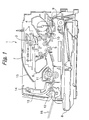
- a pickup roller 9 pays out the top sheet from the sheet cassette 8 toward a registration roller pair 10.
- the registration roller pair 10 once stops the sheet and then conveys it to a position below the belt 2 at a preselected timing.
- the image transfer charger 5 transfers the toner image from the belt 2 to the sheet.
- the sheet with the toner image is conveyed to a fixing unit 11. After the image transfer, the cleaning unit 6 removes the toner left on the belt 2.
- the fixing unit 11 fixes the toner image on the sheet.
- a solenoid-operated FD/FU (Face-UP/Face-Down) path selector 12 steers the sheet coming out of the fixing unit 11 to either one of a face-down print tray 15 and a face-up print tray 16.
- a face-down outlet roller pair 14 conveys the sheet introduced into a face-down path 13 by the path selector 12 to the face-down print tray 15 face down, i.e., with the image surface of the sheet facing downward.
- the sheet not steered into the face-down path 13 is directly driven out to the face-up print tray 16.
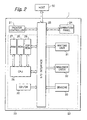
- the memory 39 is mounted on a circuit board 41 together with a thermistor 42.
- the circuit board 41 is positioned in a chamber 40 isolated from the fixing rollers 36 and 37 by a heat-insulating wall 43.
- a fan 44 is also disposed in the chamber 40 in order to cool off the circuit board 41 when temperature around the circuit board 41 rises above a preselected temperature, as determined by the thermistor 42.
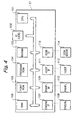
- the host IF 111 allows the printer controller 21 to interchange information with the host 112 and is usually implemented by an interface having Centronics specifications or an RS232C board.
- the host 112 is a host computer or similar host connected to the laser printer 1.
- the disk IF 113 communicates with a disk drive 114.
- the disk drive 114 may be implemented as a floppy disk drive or a hard disk drive that stores various data and print data and a program.
- the illustrative embodiment is capable of varying a sheet conveying speed in order to cope with a high resolution. For example, the illustrative embodiment lowers a linear velocity of 92 mm/sec for a resolution of 600 dpi (dots per inch) to 46 mm/sec for a resolution of 1,200 dpi. At the same time, the illustrative embodiment assigns a target fixing temperature of 180°C to 92 mm/sec and a target fixing temperature of 140°C to 46 mm/sec.
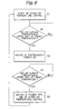
- step S10 After a sheet or print has been driven out of the printer (step S10), the engine 22 sets up a stand-by temperature newly calculated by taking account of the result of this time of operation (step S11).
- This specific procedure is also practicable with the configuration shown in FIGS. 1 through 4 and shares the sequence of steps of FIG. 6 with the previous specific procedure.
Landscapes
- Physics & Mathematics (AREA)
- General Physics & Mathematics (AREA)
- Fixing For Electrophotography (AREA)
- Control Or Security For Electrophotography (AREA)
Abstract
Description
Claims (12)
- A method for controlling the temperature of a thermal fixing unit (11) of an image forming apparatus, a sheet conveying speed of said image forming apparatus being varied in accordance with a resolution selected, comprising the steps of:varying a target fixing temperature of said fixing unit (11) in accordance with the sheet conveying speed and setting said target fixing temperature for image formation;setting a stand-by temperature of said fixing unit (11) after image formation in accordance with the resolution selected; andcontrolling the stand-by temperature of said fixing unit in accordance with the stand-by temperature set.
- A method for controlling the temperature of a thermal fixing unit (11) of an image forming apparatus, a sheet conveying speed of said image forming apparatus being varied in accordance with a resolution selected, comprising the steps of:varying a target fixing temperature of said fixing unit (11) in accordance with the sheet conveying speed and setting said target fixing temperature for image formation;setting a stand-by temperature of said fixing unit (11) after image formation adequately in accordance with a history of use of said fixing unit; andcontrolling the stand-by temperature of said fixing unit in accordance with the stand-by temperature set.
- The method according to claim 2, wherein the stand-by temperature is set on the basis of the frequency of use of an individual person using the image forming apparatus.
- The method according to claim 2, wherein said image forming apparatus is shared by a plurality of persons, in particular in a network environment, wherein for setting said stand-by temperature said stand-by temperature is varied stepwise by taking into account resolutions selected by a plurality of persons.
- The method according to claim 4, wherein said stand-by temperature to be set is calculated as an arithmetic average of the resolutions set by said plurality of persons.
- A method for controlling the temperature of a thermal fixing unit (11) of an image forming apparatus, a sheet conveying speed of said image forming apparatus being varied in accordance with a resolution selected, comprising the steps of:setting a desired resolution before an image formation;varying a target fixing temperature of said fixing unit (11) in accordance with the sheet conveying speed and setting said target fixing temperature for image formation;setting a stand-by temperature of said fixing unit (11) before and after image formation in accordance with a fixing temperature matching with said desired resolution; andcontrolling the stand-by temperature of said fixing unit before and after image formation in accordance with the stand-by temperature set.
- The method according to any of the preceding claims, wherein the stand-by temperature set is written to a nonvolatile memory (39) of said fixing unit (11).
- The method according to any of the preceding claims, wherein the stand-by temperature is input on an operation panel or a host computer connected with said image forming apparatus.
- A controlling apparatus for controlling the temperature of a thermal fixing unit (11) of an image forming apparatus, said controlling apparatus being adapted for performing the steps according to any of the preceding claims.
- An image forming apparatus for forming an image on a sheet being conveyed, said image forming apparatus being capable of varying a sheet conveying speed,
characterized by a controlling apparatus according to the preceding claim for controlling a thermal fixing unit (11) of said image forming apparatus in accordance with the method steps according to any of claims 1 to 8. - A computer program product comprising program code means for performing the steps according to any of claims 1 to 8, when said program is run on a controller (21) of a thermal fixing unit (11) of an image forming apparatus.
- A computer program product comprising program code means according to the preceding claim that are recorded on a data recording medium readable by a processor controlling a thermal fixing unit of an image forming apparatus.
Applications Claiming Priority (2)
| Application Number | Priority Date | Filing Date | Title |
|---|---|---|---|
| JP2000320999A JP2002132087A (en) | 2000-10-20 | 2000-10-20 | Image forming device |
| JP2000320999 | 2000-10-20 |
Publications (3)
| Publication Number | Publication Date |
|---|---|
| EP1199612A2 true EP1199612A2 (en) | 2002-04-24 |
| EP1199612A3 EP1199612A3 (en) | 2002-06-26 |
| EP1199612B1 EP1199612B1 (en) | 2006-05-10 |
Family
ID=18799197
Family Applications (1)
| Application Number | Title | Priority Date | Filing Date |
|---|---|---|---|
| EP01124324A Expired - Lifetime EP1199612B1 (en) | 2000-10-20 | 2001-10-19 | Method for controlling the temperature of a fixing unit, controlling apparatus, image forming apparatus and computer program product |
Country Status (4)
| Country | Link |
|---|---|
| US (1) | US6529696B2 (en) |
| EP (1) | EP1199612B1 (en) |
| JP (1) | JP2002132087A (en) |
| DE (1) | DE60119471T2 (en) |
Cited By (3)
| Publication number | Priority date | Publication date | Assignee | Title |
|---|---|---|---|---|
| EP2911009A3 (en) * | 2014-02-24 | 2015-11-25 | Konica Minolta, Inc. | Image forming apparatus |
| US20160274524A1 (en) * | 2011-09-05 | 2016-09-22 | Canon Kabushiki Kaisha | Image forming apparatus, control method therefor, and storage medium |
| EP1445666B1 (en) * | 2003-02-05 | 2018-06-06 | Brother Kogyo Kabushiki Kaisha | Multi-function processing apparatus |
Families Citing this family (4)
| Publication number | Priority date | Publication date | Assignee | Title |
|---|---|---|---|---|
| US6968137B2 (en) * | 2002-02-28 | 2005-11-22 | Matsushita Electric Industrial Co., Ltd. | Image heating device, image forming apparatus, image copying machine, and method for controlling temperature |
| JP4031416B2 (en) * | 2002-09-05 | 2008-01-09 | 株式会社リコー | File transfer system, file management server, file transfer method, program for computer to execute the method, image forming system, stored document management server, and image forming apparatus |
| JP2007078755A (en) * | 2005-09-12 | 2007-03-29 | Ricoh Co Ltd | Transfer device and image forming apparatus |
| JP5892457B2 (en) * | 2010-08-23 | 2016-03-23 | 株式会社リコー | Fixing apparatus and image forming apparatus |
Family Cites Families (10)
| Publication number | Priority date | Publication date | Assignee | Title |
|---|---|---|---|---|
| JPH02120781A (en) | 1988-10-31 | 1990-05-08 | Kyocera Corp | Temperature control method for heat fixing device |
| JP3148089B2 (en) * | 1995-03-06 | 2001-03-19 | シャープ株式会社 | Image forming device |
| JPH09233314A (en) * | 1996-02-20 | 1997-09-05 | Konica Corp | Image forming device and its control method |
| JPH09297492A (en) | 1996-05-08 | 1997-11-18 | Ricoh Co Ltd | Recording device |
| JPH10198214A (en) * | 1997-01-08 | 1998-07-31 | Canon Inc | Image forming device |
| JPH10233276A (en) * | 1997-02-18 | 1998-09-02 | Canon Inc | Heating device, image heating device, and image forming device |
| JP2000131997A (en) * | 1998-10-28 | 2000-05-12 | Casio Electronics Co Ltd | Image forming device |
| JP2000181275A (en) * | 1998-12-16 | 2000-06-30 | Fuji Xerox Co Ltd | Image forming device |
| JP3829047B2 (en) | 1999-07-01 | 2006-10-04 | 株式会社リコー | Image forming apparatus |
| JP2002040873A (en) * | 2000-05-19 | 2002-02-06 | Ricoh Co Ltd | Image forming device |
-
2000
- 2000-10-20 JP JP2000320999A patent/JP2002132087A/en active Pending
-
2001
- 2001-10-19 US US09/982,014 patent/US6529696B2/en not_active Expired - Lifetime
- 2001-10-19 EP EP01124324A patent/EP1199612B1/en not_active Expired - Lifetime
- 2001-10-19 DE DE60119471T patent/DE60119471T2/en not_active Expired - Lifetime
Cited By (5)
| Publication number | Priority date | Publication date | Assignee | Title |
|---|---|---|---|---|
| EP1445666B1 (en) * | 2003-02-05 | 2018-06-06 | Brother Kogyo Kabushiki Kaisha | Multi-function processing apparatus |
| US20160274524A1 (en) * | 2011-09-05 | 2016-09-22 | Canon Kabushiki Kaisha | Image forming apparatus, control method therefor, and storage medium |
| US10895839B2 (en) * | 2011-09-05 | 2021-01-19 | Canon Kabushiki Kaisha | Image forming apparatus, control method therefor, and storage medium |
| EP2911009A3 (en) * | 2014-02-24 | 2015-11-25 | Konica Minolta, Inc. | Image forming apparatus |
| US9395664B2 (en) | 2014-02-24 | 2016-07-19 | Konica Minolta, Inc. | Image forming apparatus |
Also Published As
| Publication number | Publication date |
|---|---|
| EP1199612A3 (en) | 2002-06-26 |
| US20020048465A1 (en) | 2002-04-25 |
| US6529696B2 (en) | 2003-03-04 |
| JP2002132087A (en) | 2002-05-09 |
| EP1199612B1 (en) | 2006-05-10 |
| DE60119471D1 (en) | 2006-06-14 |
| DE60119471T2 (en) | 2007-04-19 |
Similar Documents
| Publication | Publication Date | Title |
|---|---|---|
| KR100400908B1 (en) | Method and apparatus for image forming capable of appropriately changing a fixing temperature | |
| US20080226323A1 (en) | Image forming apparatus and control method thereof | |
| JP2941827B2 (en) | Recording device | |
| US8351073B2 (en) | Image forming apparatus and color deviation correcting method and program | |
| CN103870217B (en) | Printing apparatus and control method of the printing apparatus | |
| US20110229183A1 (en) | Image processing device for processing jobs to be executed by image forming device including fixing unit | |
| US11360415B2 (en) | Image forming apparatus and method of controlling image forming apparatus | |
| US6529696B2 (en) | Image forming apparatus having variable sheet-conveying speed | |
| US5081493A (en) | Method of controlling thermal fixing unit for electronic transfer printer | |
| US8179557B2 (en) | Image forming apparatus for reading information from and writing information to a non-contact medium | |
| JP7814909B2 (en) | Image forming device | |
| JPH10288911A (en) | Electrophotographic device | |
| JPH1195626A (en) | Image forming device | |
| US20070041742A1 (en) | Image forming apparatus and fixing apparatus thereof | |
| JP4696791B2 (en) | Image forming apparatus and control method thereof | |
| JP4417790B2 (en) | Image forming method and image forming apparatus | |
| US7680423B2 (en) | Image forming apparatus and method for controlling wear of a photoconductor drum | |
| JPH07181830A (en) | Image forming device | |
| JP2003280447A (en) | Image forming device | |
| JP2003202777A (en) | Image forming device | |
| JP2003131467A (en) | Printing apparatus and density correction method thereof | |
| JP2018025645A (en) | Image forming apparatus | |
| JP2003151720A (en) | Heating device and image forming apparatus provided with the same | |
| EP0559121A1 (en) | Image forming apparatus and method | |
| JP2021173772A (en) | Image forming apparatus and image forming method |
Legal Events
| Date | Code | Title | Description |
|---|---|---|---|
| PUAI | Public reference made under article 153(3) epc to a published international application that has entered the european phase |
Free format text: ORIGINAL CODE: 0009012 |
|
| 17P | Request for examination filed |
Effective date: 20011019 |
|
| AK | Designated contracting states |
Kind code of ref document: A2 Designated state(s): AT BE CH CY DE DK ES FI FR GB GR IE IT LI LU MC NL PT SE TR |
|
| AX | Request for extension of the european patent |
Free format text: AL;LT;LV;MK;RO;SI |
|
| PUAL | Search report despatched |
Free format text: ORIGINAL CODE: 0009013 |
|
| AK | Designated contracting states |
Kind code of ref document: A3 Designated state(s): AT BE CH CY DE DK ES FI FR GB GR IE IT LI LU MC NL PT SE TR |
|
| AX | Request for extension of the european patent |
Free format text: AL;LT;LV;MK;RO;SI |
|
| 17Q | First examination report despatched |
Effective date: 20020918 |
|
| AKX | Designation fees paid |
Designated state(s): DE FR GB |
|
| GRAP | Despatch of communication of intention to grant a patent |
Free format text: ORIGINAL CODE: EPIDOSNIGR1 |
|
| GRAS | Grant fee paid |
Free format text: ORIGINAL CODE: EPIDOSNIGR3 |
|
| GRAA | (expected) grant |
Free format text: ORIGINAL CODE: 0009210 |
|
| AK | Designated contracting states |
Kind code of ref document: B1 Designated state(s): DE FR GB |
|
| REG | Reference to a national code |
Ref country code: GB Ref legal event code: FG4D |
|
| REF | Corresponds to: |
Ref document number: 60119471 Country of ref document: DE Date of ref document: 20060614 Kind code of ref document: P |
|
| ET | Fr: translation filed | ||
| PLBE | No opposition filed within time limit |
Free format text: ORIGINAL CODE: 0009261 |
|
| STAA | Information on the status of an ep patent application or granted ep patent |
Free format text: STATUS: NO OPPOSITION FILED WITHIN TIME LIMIT |
|
| 26N | No opposition filed |
Effective date: 20070213 |
|
| REG | Reference to a national code |
Ref country code: FR Ref legal event code: PLFP Year of fee payment: 15 |
|
| REG | Reference to a national code |
Ref country code: FR Ref legal event code: PLFP Year of fee payment: 16 |
|
| PGFP | Annual fee paid to national office [announced via postgrant information from national office to epo] |
Ref country code: GB Payment date: 20161020 Year of fee payment: 16 |
|
| REG | Reference to a national code |
Ref country code: FR Ref legal event code: PLFP Year of fee payment: 17 |
|
| PGFP | Annual fee paid to national office [announced via postgrant information from national office to epo] |
Ref country code: FR Payment date: 20171024 Year of fee payment: 17 Ref country code: DE Payment date: 20171019 Year of fee payment: 17 |
|
| GBPC | Gb: european patent ceased through non-payment of renewal fee |
Effective date: 20171019 |
|
| PG25 | Lapsed in a contracting state [announced via postgrant information from national office to epo] |
Ref country code: GB Free format text: LAPSE BECAUSE OF NON-PAYMENT OF DUE FEES Effective date: 20171019 |
|
| REG | Reference to a national code |
Ref country code: DE Ref legal event code: R119 Ref document number: 60119471 Country of ref document: DE |
|
| PG25 | Lapsed in a contracting state [announced via postgrant information from national office to epo] |
Ref country code: DE Free format text: LAPSE BECAUSE OF NON-PAYMENT OF DUE FEES Effective date: 20190501 |
|
| PG25 | Lapsed in a contracting state [announced via postgrant information from national office to epo] |
Ref country code: FR Free format text: LAPSE BECAUSE OF NON-PAYMENT OF DUE FEES Effective date: 20181031 |