EP1199491A1 - Block of friction material with integrated wear sensor - Google Patents
Block of friction material with integrated wear sensor Download PDFInfo
- Publication number
- EP1199491A1 EP1199491A1 EP00309146A EP00309146A EP1199491A1 EP 1199491 A1 EP1199491 A1 EP 1199491A1 EP 00309146 A EP00309146 A EP 00309146A EP 00309146 A EP00309146 A EP 00309146A EP 1199491 A1 EP1199491 A1 EP 1199491A1
- Authority
- EP
- European Patent Office
- Prior art keywords
- block
- sheet
- foil
- friction material
- friction
- Prior art date
- Legal status (The legal status is an assumption and is not a legal conclusion. Google has not performed a legal analysis and makes no representation as to the accuracy of the status listed.)
- Withdrawn
Links
- 239000002783 friction material Substances 0.000 title claims abstract description 34
- 239000011888 foil Substances 0.000 claims abstract description 20
- 238000012544 monitoring process Methods 0.000 abstract 1
- 239000011236 particulate material Substances 0.000 description 7
- KXGFMDJXCMQABM-UHFFFAOYSA-N 2-methoxy-6-methylphenol Chemical compound [CH]OC1=CC=CC([CH])=C1O KXGFMDJXCMQABM-UHFFFAOYSA-N 0.000 description 3
- 238000005259 measurement Methods 0.000 description 3
- 239000005011 phenolic resin Substances 0.000 description 3
- 229920001568 phenolic resin Polymers 0.000 description 3
- 229910001006 Constantan Inorganic materials 0.000 description 2
- 229910045601 alloy Inorganic materials 0.000 description 2
- 239000000956 alloy Substances 0.000 description 2
- 238000009413 insulation Methods 0.000 description 2
- 229910001018 Cast iron Inorganic materials 0.000 description 1
- 230000001154 acute effect Effects 0.000 description 1
- 239000000853 adhesive Substances 0.000 description 1
- 230000001070 adhesive effect Effects 0.000 description 1
- 239000011230 binding agent Substances 0.000 description 1
- 239000003990 capacitor Substances 0.000 description 1
- 238000005266 casting Methods 0.000 description 1
- 230000000694 effects Effects 0.000 description 1
- 239000012777 electrically insulating material Substances 0.000 description 1
- 239000012774 insulation material Substances 0.000 description 1
- 238000003754 machining Methods 0.000 description 1
- 238000004519 manufacturing process Methods 0.000 description 1
- 239000000463 material Substances 0.000 description 1
- 238000012986 modification Methods 0.000 description 1
- 230000004048 modification Effects 0.000 description 1
- 239000004033 plastic Substances 0.000 description 1
- 229920003023 plastic Polymers 0.000 description 1
- 238000003825 pressing Methods 0.000 description 1
- 230000000750 progressive effect Effects 0.000 description 1
- 230000003313 weakening effect Effects 0.000 description 1
Images

Classifications
-
- F—MECHANICAL ENGINEERING; LIGHTING; HEATING; WEAPONS; BLASTING
- F16—ENGINEERING ELEMENTS AND UNITS; GENERAL MEASURES FOR PRODUCING AND MAINTAINING EFFECTIVE FUNCTIONING OF MACHINES OR INSTALLATIONS; THERMAL INSULATION IN GENERAL
- F16D—COUPLINGS FOR TRANSMITTING ROTATION; CLUTCHES; BRAKES
- F16D66/00—Arrangements for monitoring working conditions, e.g. wear, temperature
- F16D66/02—Apparatus for indicating wear
Definitions
- This invention is concerned with a block of friction material.
- a frictional braking force is applied to a moving member by pressing a block of friction material into engagement with the member.
- a block of friction material is pressed against an annular planar side surface of the moving disc.
- a similar block of friction material is pressed against an opposite side surface of the disc.
- the blocks are supported against movement circumferentially of the disc so that frictional braking forces are created on both sides of the disc, reducing its rotational speed.
- a block of friction material defines a surface, referred to herein as "a friction surface", which is for engaging a member to apply a frictional force to the member.
- the friction surface is usually parallel to the surface of the member which the block engages.
- the friction surfaces of the blocks are planar.
- the friction surface In blocks intended to engage the inner surface of a drum of a drum brake, the friction surface is in the form of part of a convex cylinder.
- the friction surface In blocks intended to engage a convex surface, for example the periphery of a wheel, the friction surface is in the form of part of a concave cylinder.
- the block is mounted on a backing plate which extends parallel to the friction surface on the opposite side of the block. In some cases, for example where the block is mounted between two discs of a multi-disc disc brake, the block has more than one friction surface.
- the invention is applicable to blocks of friction material for brakes of any of these types and for other purposes.
- an electrically-conductive wire is contained within the block of friction material. An end of the wire is positioned at a distance from the friction surface, said distance being judged to correspond to an approach to critical wear.
- the wire is connected, through the support of the block, to an electrical circuit to which the disc is also connected. When sufficient wear has occurred, the disc contacts the end of the wire, completing the circuit and thereby causing operation of a warning device.
- this type of monitor has the disadvantage that it can only provide an indication that wear has progressed to a particular extent at a particular point.
- the invention provides a block of friction material, the block defining a friction surface for engaging a member to apply a frictional force to the member, the block having an electrically-conducting member contained therein, characterised in that the electrically-conducting member is in the form of a sheet of foil.
- a block according to the invention can be used with an automatically-operating monitor of the wear of the block of friction material of the type referred to above.
- the sheet of foil can cover a greater area than the afore-mentioned wire, by being arranged so that the sheet is equi-distant from the friction surface, ie so that the plane of the sheet is substantially parallel to the friction surface.
- an area may be covered by the sheet being arranged so that the sheet extends in a direction which is towards-and-away from the friction surface, ie so that the plane of the sheet is substantially normal to the friction surface or makes an angle, preferably an acute angle, to the normal to the friction surface, and the edge of the sheet which is nearest to the friction surface following a path around and/or through said area.
- a block according to the invention can, alternatively, be used with an automatically-operating monitor of the wear of the block of friction material which is different from the type referred to above.
- a monitor may be arranged to detect continuously, or on demand the amount of wear which has occurred in the block.
- Such a monitor may detect change of electrical resistance as the sheet of foil wears away.
- the sheet may taper in width either towards or away from the friction surface.
- Such a monitor may, alternatively, detect change of inductance as the foil wears away.
- the sheet may be formed into a closed loop, eg a flat loop, such as an annular loop, or an elongated loop such as a cylinder, a cone, or a frusto-cone.
- a closed loop eg a flat loop, such as an annular loop, or an elongated loop such as a cylinder, a cone, or a frusto-cone.
- the sheet may be die-cut or otherwise formed into a multi-component portion of an electrical component and the connections between the components.
- the sheet may be formed as a plurality of resistors, capacitors, or inductors connected in series or parallel, or as resistors arranged in a Wheatstone bridge.
- the sheet of foil may be perforated by holes in which friction material is received.
- the sheet of foil is preferably of substantially constant thickness and less than 1mm thick. Preferably, the sheet is less than 0.5mm, more preferably less than 0,2mm, in thickness. A sheet 0.1mm in thickness and made from the alloy known as "Constantan" is suitable in some cases.
- the sheet of foil may be coated with electrically-insulating material, in order to prevent electrically-conducting components in the friction material or its backing plate from affecting the monitor's output.
- the sheet of foil is electrically connected to a plug or a socket.
- a plug or socket may be mounted in a recess in the backing plate of the friction material.
- a recess may be cast-in if the plate is a casting.
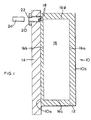
- the first illustrative block 10 shown in Figure 1 is a block of friction material 12 for use in a disc brake.
- the friction material 12 is of the conventional type which comprises particulate materials bonded together by phenolic resin.
- the friction material 12 is adhered to a cast iron backing plate 14.
- the block 10 is generally rectangular in transverse cross-section as shown in Figure 1 and, in plan view, has the same shape as the block shown in Figure 2.
- the block 10 is bounded by a planar surface 10a which engages and is adhered to the backing plate 14 and a planar surface 10b which extends parallel to the surface 10a on the opposite side of the block 10, ie the surfaces 10a and 10b are spaced from one another by the thickness of the block 10 and face in opposite directions.
- the surface 10b is a friction surface of the block 10 for engaging a rotor of the disc brake (not shown) to apply a frictional force to the rotor.
- the block 10 has an electrically-conducting member in the form of a rectangular sheet of foil 16 contained therein.
- the sheet 16 is made of the alloy known as Constantan and is 0.1mm in thickness.
- the sheet 16 is coated on both of its major surfaces with a thin layer of electrically-insulating plastics material.
- the sheet 16 extends through most of the thickness of the friction material 12 but without reaching the surfaces 10a and 10b.
- the sheet 16 is arranged so that the plane of the sheet 16, ie the plane of its major surfaces, is substantially normal to the friction surface 10b.
- one of the longer edges 16a of the sheet 16 extends parallel to the friction surface 10b and is adjacent thereto and the other longer edge 16b of the sheet 16 extends parallel to the surface 10a and is adjacent thereto.
- the sheet 16 extends in a substantially straight line across most of the width of the block 10 so that the shorter edges 16c and 16d of the sheet extend parallel to and are adjacent to the sides of the block 10.
- the shorter edges 16c and 16d are both connected to electrically-conducting wires 18 which extend through the friction material 12 to a socket 20 which is mounted on the backing plate 14.
- the socket 20 is mounted in a recess 22 of the plate 14 which was cast-in when the plate 14 was cast.
- the socket 20 is arranged to receive a plug 24 to connect the wires 18 to a resistance-measuring electrical circuit (not shown).
- the measuring circuit provides an automatically-operating monitor of the wear of a block 10 during the operation of the disc brake. Specifically, the measuring circuit measures the electrical resistance between the wires 18 caused by the presence of the sheet 16. The measurements are taken when the disc brake is in a brakes-on condition in which the block 10 is pressed against the rotor of the disc brake.
- the measuring circuit does not detect any wear because the layer of friction material 12 between the edge 16a of the sheet 16 and the friction surface 10b electrically insulates the sheet 16 from the rotor. If the friction material 12 is electrically conductive, the insulation can be achieved by a thin layer of insulation material on the sheet 16.
- the rotor contacts the edge 16a, completing an electrical circuit through the rotor and the sheet 16. Completion of the circuit allows the measurement of the electrical resistance of the sheet 16 and indicates that wear has progressed as far as the edge 16a.
- the sheet 16 is worn away with the friction material 12, thereby reducing the width of the sheet 16 and increasing its electrical resistance. The measuring circuit detects this increase in resistance which corresponds to the measurement of the progressive wear of the block 10.
- the sheet 16 and the wires 18 are positioned in a die cavity, particulate material including uncured phenolic resin is introduced into the cavity so that the particulate material surrounds the sheet 16 and the wires 18, and the backing plate 14 is positioned over an opening to the cavity so that the backing plate contacts the particulate material and the wires extend into the recess 22.
- the particulate material is then compressed against the backing plate 14 and the phenolic resin is cured to bind the particulate material together to form the friction material 12 which has the sheet 16 and the wires 18 contained or embedded therein.
- a modification of the block 10 may be manufactured by first forming the friction material from particulate material bound together by cured binder, machining a slot into the block, inserting the sheet 16 into the slot, and securing the sheet 16 in position, eg by adhesive.
- the second illustrative block 30 shown in Figure 2 is similar to the first illustrative block 10, except as described below, and like reference numerals are used for like parts without further description.
- the block 30 differs from the block 10 in that the sheet 16 of foil does not extend in a straight line across the block 30 but instead extends along a path which is generally circular but has a gap therein bounded by the shorter edges 16c and 16d of the sheet 16 which, accordingly, do not contact one another. In this way, the sheet 16 can be used to monitor wear in the area of the block 10 where the path of the sheet 16 is located. If desired, one or more further sheets 16 can be positioned in other areas of the block 30 so that wear in different areas can be individually monitored.
Landscapes
- Engineering & Computer Science (AREA)
- General Engineering & Computer Science (AREA)
- Mechanical Engineering (AREA)
- Braking Arrangements (AREA)
Abstract
Description
Claims (8)
- A block (10) of friction material, the block defining a friction surface (10b) for engaging a member to apply a frictional force to the member, the block having an electrically-conducting member (16) contained therein, characterised in that the electrically-conducting member is in the form of a sheet of foil.
- A block according to claim 1, characterised in that the sheet (16) of foil is arranged so that the plane of the sheet is substantially parallel to the friction surface (10b).
- A block according to claim 1, characterised in that the sheet (16) of foil is arranged so that the plane of the sheet is substantially normal to the friction surface (10b) or makes an angle to the normal to the friction surface.
- A block according to claim 3, characterised in that the sheet (16) of foil tapers in width either towards or away from the friction surface (10b).
- A block according to any one of claims 1 to 3, characterised in that the sheet (16) of foil is formed into a closed loop.
- A block according to any one of claims 1 to 5, characterised in that the sheet (16) of foil is die-cut or otherwise formed into a multi-component portion of an electrical component and the connections between the components.
- A block according to any one of claims 1 to 6, characterised in that the sheet (16) of foil is perforated by holes in which friction material (12) is received.
- A block according to any one of claims 1 to 7, characterised in that the sheet (16) of foil is less than 0.2mm in thickness.
Priority Applications (1)
| Application Number | Priority Date | Filing Date | Title |
|---|---|---|---|
| EP00309146A EP1199491A1 (en) | 2000-10-17 | 2000-10-17 | Block of friction material with integrated wear sensor |
Applications Claiming Priority (1)
| Application Number | Priority Date | Filing Date | Title |
|---|---|---|---|
| EP00309146A EP1199491A1 (en) | 2000-10-17 | 2000-10-17 | Block of friction material with integrated wear sensor |
Publications (1)
| Publication Number | Publication Date |
|---|---|
| EP1199491A1 true EP1199491A1 (en) | 2002-04-24 |
Family
ID=8173323
Family Applications (1)
| Application Number | Title | Priority Date | Filing Date |
|---|---|---|---|
| EP00309146A Withdrawn EP1199491A1 (en) | 2000-10-17 | 2000-10-17 | Block of friction material with integrated wear sensor |
Country Status (1)
| Country | Link |
|---|---|
| EP (1) | EP1199491A1 (en) |
Cited By (2)
| Publication number | Priority date | Publication date | Assignee | Title |
|---|---|---|---|---|
| EP1431606A1 (en) * | 2002-12-18 | 2004-06-23 | TMD Friction Europe GmbH | Brake or clutch lining with integrated force measurement |
| US11261028B2 (en) * | 2017-07-26 | 2022-03-01 | International Materials & Technology Pty Limited | Wear liners |
Citations (4)
| Publication number | Priority date | Publication date | Assignee | Title |
|---|---|---|---|---|
| FR2319880A1 (en) * | 1975-07-29 | 1977-02-25 | Tromeur Jean | Brake lining monitoring system - uses sensor elements embedded in lining to give warning of high temp. and wear |
| FR2574508A1 (en) * | 1984-12-11 | 1986-06-13 | Renault | FRICTION TRIM WEAR DETECTOR |
| US4646001A (en) * | 1983-11-21 | 1987-02-24 | Morganite Electrical Carbon Limited | Resistive wear sensors |
| DE4231107A1 (en) * | 1992-09-17 | 1994-03-24 | Bosch Gmbh Robert | Sensor for measuring thickness and temp. of brake linings, esp. in vehicle - has high impedance electrical resistance in or on brake lining and coupled to temp. dependent resistance |
-
2000
- 2000-10-17 EP EP00309146A patent/EP1199491A1/en not_active Withdrawn
Patent Citations (4)
| Publication number | Priority date | Publication date | Assignee | Title |
|---|---|---|---|---|
| FR2319880A1 (en) * | 1975-07-29 | 1977-02-25 | Tromeur Jean | Brake lining monitoring system - uses sensor elements embedded in lining to give warning of high temp. and wear |
| US4646001A (en) * | 1983-11-21 | 1987-02-24 | Morganite Electrical Carbon Limited | Resistive wear sensors |
| FR2574508A1 (en) * | 1984-12-11 | 1986-06-13 | Renault | FRICTION TRIM WEAR DETECTOR |
| DE4231107A1 (en) * | 1992-09-17 | 1994-03-24 | Bosch Gmbh Robert | Sensor for measuring thickness and temp. of brake linings, esp. in vehicle - has high impedance electrical resistance in or on brake lining and coupled to temp. dependent resistance |
Cited By (2)
| Publication number | Priority date | Publication date | Assignee | Title |
|---|---|---|---|---|
| EP1431606A1 (en) * | 2002-12-18 | 2004-06-23 | TMD Friction Europe GmbH | Brake or clutch lining with integrated force measurement |
| US11261028B2 (en) * | 2017-07-26 | 2022-03-01 | International Materials & Technology Pty Limited | Wear liners |
Similar Documents
| Publication | Publication Date | Title |
|---|---|---|
| US4824260A (en) | Brake block temperature and wear measuring device | |
| US7165657B2 (en) | Thin film sensor for brake lining pad wear and brake temperature sensing | |
| US6477893B1 (en) | Erodable sensor for progressive brake wear detection | |
| KR930010443B1 (en) | Wear indicator for friction lining | |
| US6250429B1 (en) | Brake shoe assembly having a resistive brake lining wear sensor | |
| JP2010501796A (en) | Temperature and wear sensors for brake or clutch devices | |
| US6250430B1 (en) | System and method for determining brake lining wear using a temperature detector and a brake actuation system | |
| EP1798440A1 (en) | Brake lining wear sensor | |
| US6260665B1 (en) | System and method for determining brake lining wear based on cooling wave propagation time | |
| US6236310B1 (en) | Brake shoe assembly having a brake lining wear and temperature sensor | |
| EP3289238B1 (en) | Brake pad for vehicles | |
| EP1399681B1 (en) | Brake lining wear system | |
| EP1199491A1 (en) | Block of friction material with integrated wear sensor | |
| KR102239046B1 (en) | Systems and methods for brake sensing | |
| KR102858484B1 (en) | Braking and/or clamping device with integrated split housing and sensor module | |
| EP0419207B1 (en) | Friction lining condition monitoring system | |
| US20050077122A1 (en) | Clip on electronic lining wear sensor | |
| WO1998046901A1 (en) | Lining wear indicator for a drum brake | |
| CA1084426A (en) | Disc brake wear indicator | |
| JP2004505222A (en) | Disc brake | |
| JP2006177399A (en) | Wear detection device | |
| EP4477485A1 (en) | Heavy vehicle brake assembly | |
| JPH109307A (en) | Brake friction member wear and overheat detection device | |
| CN106030145B (en) | For the disk brake of commerial vehicle | |
| JPS6111549Y2 (en) |
Legal Events
| Date | Code | Title | Description |
|---|---|---|---|
| PUAI | Public reference made under article 153(3) epc to a published international application that has entered the european phase |
Free format text: ORIGINAL CODE: 0009012 |
|
| AK | Designated contracting states |
Kind code of ref document: A1 Designated state(s): DE ES FR GB IT Kind code of ref document: A1 Designated state(s): AT BE CH CY DE DK ES FI FR GB GR IE IT LI LU MC NL PT SE |
|
| AX | Request for extension of the european patent |
Free format text: AL;LT;LV;MK;RO;SI |
|
| 17P | Request for examination filed |
Effective date: 20021017 |
|
| AKX | Designation fees paid |
Free format text: DE ES FR GB IT |
|
| 17Q | First examination report despatched |
Effective date: 20050128 |
|
| STAA | Information on the status of an ep patent application or granted ep patent |
Free format text: STATUS: THE APPLICATION IS DEEMED TO BE WITHDRAWN |
|
| 18D | Application deemed to be withdrawn |
Effective date: 20050608 |