EP1199379A1 - Low friction coefficient carbon film and method of forming the same - Google Patents
Low friction coefficient carbon film and method of forming the same Download PDFInfo
- Publication number
- EP1199379A1 EP1199379A1 EP01124708A EP01124708A EP1199379A1 EP 1199379 A1 EP1199379 A1 EP 1199379A1 EP 01124708 A EP01124708 A EP 01124708A EP 01124708 A EP01124708 A EP 01124708A EP 1199379 A1 EP1199379 A1 EP 1199379A1
- Authority
- EP
- European Patent Office
- Prior art keywords
- gas
- carbon film
- carbon
- base material
- film
- Prior art date
- Legal status (The legal status is an assumption and is not a legal conclusion. Google has not performed a legal analysis and makes no representation as to the accuracy of the status listed.)
- Granted
Links
- 229910052799 carbon Inorganic materials 0.000 title claims abstract description 213
- OKTJSMMVPCPJKN-UHFFFAOYSA-N Carbon Chemical compound [C] OKTJSMMVPCPJKN-UHFFFAOYSA-N 0.000 title claims abstract description 209
- 238000000034 method Methods 0.000 title claims description 33
- 239000000463 material Substances 0.000 claims abstract description 71
- UHOVQNZJYSORNB-UHFFFAOYSA-N Benzene Chemical compound C1=CC=CC=C1 UHOVQNZJYSORNB-UHFFFAOYSA-N 0.000 claims description 78
- VNWKTOKETHGBQD-UHFFFAOYSA-N methane Chemical compound C VNWKTOKETHGBQD-UHFFFAOYSA-N 0.000 claims description 59
- OKKJLVBELUTLKV-UHFFFAOYSA-N Methanol Chemical compound OC OKKJLVBELUTLKV-UHFFFAOYSA-N 0.000 claims description 21
- BOTDANWDWHJENH-UHFFFAOYSA-N Tetraethyl orthosilicate Chemical compound CCO[Si](OCC)(OCC)OCC BOTDANWDWHJENH-UHFFFAOYSA-N 0.000 claims description 16
- VLKZOEOYAKHREP-UHFFFAOYSA-N n-Hexane Chemical compound CCCCCC VLKZOEOYAKHREP-UHFFFAOYSA-N 0.000 claims description 15
- LFQSCWFLJHTTHZ-UHFFFAOYSA-N Ethanol Chemical compound CCO LFQSCWFLJHTTHZ-UHFFFAOYSA-N 0.000 claims description 14
- CSCPPACGZOOCGX-UHFFFAOYSA-N Acetone Chemical compound CC(C)=O CSCPPACGZOOCGX-UHFFFAOYSA-N 0.000 claims description 13
- GWEVSGVZZGPLCZ-UHFFFAOYSA-N Titan oxide Chemical compound O=[Ti]=O GWEVSGVZZGPLCZ-UHFFFAOYSA-N 0.000 claims description 12
- XDTMQSROBMDMFD-UHFFFAOYSA-N Cyclohexane Chemical compound C1CCCCC1 XDTMQSROBMDMFD-UHFFFAOYSA-N 0.000 claims description 5
- TVMXDCGIABBOFY-UHFFFAOYSA-N octane Chemical compound CCCCCCCC TVMXDCGIABBOFY-UHFFFAOYSA-N 0.000 claims description 5
- 229920001296 polysiloxane Polymers 0.000 claims description 4
- OGIDPMRJRNCKJF-UHFFFAOYSA-N titanium oxide Inorganic materials [Ti]=O OGIDPMRJRNCKJF-UHFFFAOYSA-N 0.000 claims description 4
- 229910044991 metal oxide Inorganic materials 0.000 claims description 3
- 239000007789 gas Substances 0.000 description 147
- 125000004430 oxygen atom Chemical group O* 0.000 description 11
- 239000000203 mixture Substances 0.000 description 9
- 230000000052 comparative effect Effects 0.000 description 6
- 150000001721 carbon Chemical class 0.000 description 4
- 239000004215 Carbon black (E152) Substances 0.000 description 3
- 229920001971 elastomer Polymers 0.000 description 3
- 229930195733 hydrocarbon Natural products 0.000 description 3
- 150000002430 hydrocarbons Chemical class 0.000 description 3
- 239000004033 plastic Substances 0.000 description 3
- 239000005060 rubber Substances 0.000 description 3
- 229920002379 silicone rubber Polymers 0.000 description 3
- 230000000694 effects Effects 0.000 description 2
- 239000000314 lubricant Substances 0.000 description 2
- 239000004945 silicone rubber Substances 0.000 description 2
- 238000006467 substitution reaction Methods 0.000 description 2
- QVGXLLKOCUKJST-UHFFFAOYSA-N atomic oxygen Chemical compound [O] QVGXLLKOCUKJST-UHFFFAOYSA-N 0.000 description 1
- 238000011161 development Methods 0.000 description 1
- 230000018109 developmental process Effects 0.000 description 1
- 238000010494 dissociation reaction Methods 0.000 description 1
- 230000005593 dissociations Effects 0.000 description 1
- 238000002474 experimental method Methods 0.000 description 1
- 229910052760 oxygen Inorganic materials 0.000 description 1
- 239000001301 oxygen Substances 0.000 description 1
- RVTZCBVAJQQJTK-UHFFFAOYSA-N oxygen(2-);zirconium(4+) Chemical compound [O-2].[O-2].[Zr+4] RVTZCBVAJQQJTK-UHFFFAOYSA-N 0.000 description 1
- 238000005268 plasma chemical vapour deposition Methods 0.000 description 1
- 230000003746 surface roughness Effects 0.000 description 1
- 229910001928 zirconium oxide Inorganic materials 0.000 description 1
Images



Classifications
-
- C—CHEMISTRY; METALLURGY
- C23—COATING METALLIC MATERIAL; COATING MATERIAL WITH METALLIC MATERIAL; CHEMICAL SURFACE TREATMENT; DIFFUSION TREATMENT OF METALLIC MATERIAL; COATING BY VACUUM EVAPORATION, BY SPUTTERING, BY ION IMPLANTATION OR BY CHEMICAL VAPOUR DEPOSITION, IN GENERAL; INHIBITING CORROSION OF METALLIC MATERIAL OR INCRUSTATION IN GENERAL
- C23C—COATING METALLIC MATERIAL; COATING MATERIAL WITH METALLIC MATERIAL; SURFACE TREATMENT OF METALLIC MATERIAL BY DIFFUSION INTO THE SURFACE, BY CHEMICAL CONVERSION OR SUBSTITUTION; COATING BY VACUUM EVAPORATION, BY SPUTTERING, BY ION IMPLANTATION OR BY CHEMICAL VAPOUR DEPOSITION, IN GENERAL
- C23C16/00—Chemical coating by decomposition of gaseous compounds, without leaving reaction products of surface material in the coating, i.e. chemical vapour deposition [CVD] processes
- C23C16/22—Chemical coating by decomposition of gaseous compounds, without leaving reaction products of surface material in the coating, i.e. chemical vapour deposition [CVD] processes characterised by the deposition of inorganic material, other than metallic material
- C23C16/26—Deposition of carbon only
-
- Y—GENERAL TAGGING OF NEW TECHNOLOGICAL DEVELOPMENTS; GENERAL TAGGING OF CROSS-SECTIONAL TECHNOLOGIES SPANNING OVER SEVERAL SECTIONS OF THE IPC; TECHNICAL SUBJECTS COVERED BY FORMER USPC CROSS-REFERENCE ART COLLECTIONS [XRACs] AND DIGESTS
- Y10—TECHNICAL SUBJECTS COVERED BY FORMER USPC
- Y10T—TECHNICAL SUBJECTS COVERED BY FORMER US CLASSIFICATION
- Y10T428/00—Stock material or miscellaneous articles
- Y10T428/30—Self-sustaining carbon mass or layer with impregnant or other layer
Definitions
- the present invention relates to a carbon film to be formed on the surface of a soft base material such as rubber or plastic (for example, such a carbon film having characteristics as low friction coefficient or low wear, to be used to such as sliding portion of machine parts), and a method of forming the same.
- carbon film Being high in hardness, carbon film is much used to cover the surface of metallic base material demanded to have high hardness as tools or parts of vehicles.
- the carbon film is also sometime covered on the surfaces of soft base material such as rubber or plastic.
- soft base material such as rubber or plastic.
- it has a merit to decrease frictional resistance on the surface and provide high hardness as maintaining the flexibility of soft base material.
- recently studies and developments have rapidly been advanced for covering the carbon film on the surfaces of soft base material.
- the soft base material For covering the carbon film on the surface of soft base material, for example, the soft base material is located within a closed film forming container, a gas containing carbon is introduced into the container, the gas is made plasma by use of means for making the gas plasma (for example, means as a high frequency discharge) , and a carbon film containing carbon as a main component is formed on the surface of soft base material under the plasma.
- a gas containing carbon for example, means as a high frequency discharge
- the soft base material with carbon film formed thus is often used as a sliding member.
- the soft base material covered with the carbon film is slid together with other article under pressure.
- the sliding member composed of the soft base material with the carbon film is used under various circumstances.
- a predetermined pressure is loaded on the surface of the soft base material with the carbon film, and at this time, friction coefficient of the carbon film is demanded to be low for maintaining a function as the sliding member.
- the friction coefficient of the carbon film is low and desirable; however, if being under pressure larger than this value, the friction coefficient of the carbon film is sometimes high, so that the function as the sliding member cannot be maintained.
- the carbon film containing carbon as the main component, formed on the surface of soft base material is divided by cracks into a plurality of regions.
- the carbon film may be produced by, for example, the following carbon film forming apparatus.
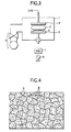
- Fig. 3 of attached drawings shows an existing carbon film forming apparatus by Plasma CVD Process where methane gas is a raw gas.
- This carbon film forming apparatus comprises a film forming container 1, a vacuum exhaust apparatus 2, a shower plate 3, and means for making plasma the gas (herein, a high frequency electrode 5 connected to a high frequency power source 8 via a matching box 7).
- the vacuum exhaust apparatus 2 enables to exhaust an air from an interior of the film forming container 1.
- the shower plate 3 introduces a gas containing carbon (herein, methane gas) into the film forming container 1 vacuum-exhausted by the vacuum exhaust apparatus 2.
- the means for making plasma the gas makes the gas introduced into the film forming container 1 through the shower plate 3 plasma.
- the high frequency electrode 5 may mount the soft base material 4 thereon.
- the high frequency electrode 5 is impressed the high frequency voltage from the high frequency power source 8 via the matching box 7. Thereby, the gas introduced into the container 1 is made plasma which is to be formed at a position shown with numeral 6 in the drawing.
- the soft base material 4 is located on the high frequency electrode 5 in the film forming container 1, and the interior of the container 1 is closed. While the interior of the closed container 1 is vacuum-discharged by the vacuum exhaust apparatus 2, the methane gas (CH 4 ) is introduced as the raw gas from the shower plate 3, and the interior of the container 1 is maintained at a desired film forming pressure. In general, the pressure within the vacuum container 1 ranges 0.1 to 10 Pa.
- the high frequency electrode 5 mounting the soft base material 4 thereon is impressed with the high frequency voltage. Then, a methane gas plasma 6 is formed within the film forming container 1, and carbon being a composing element of methane is deposited on the soft base material 4.
- the carbon film is formed on the soft base material 4.
- the methane gas is employed as the raw gas, and when the carbon film is formed on the soft base material, benzene gas (C 6 H 6 ) is generally used other than the methane gas.
- Fig. 4 shows a schematically enlarged view of the surface condition of the carbon film grown by use of the methane gas or benzene gas.
- each of regions B surrounded by cracks A in the carbon film shall be called as "block" .
- the average area of the block B when forming the carbon film on the soft base material, if changing conditions such as an electric power supplied in the formed film, the average area of the block B may be changed.
- the average area of the block B ranges around 0.01 x 10 -3 mm 2 to 0.1 to 10 -3 mm 2
- the benzene gas when the raw gas, it ranges around 0.06 x 10 -3 mm 2 to 0.12 to 10 -3 mm 2 .
- the inventor made further studies to investigate the relationship between the average area of the block B and the friction coefficient of the carbon film. It was found that a close correlation was present between them. That is, when the average range of the block B was smaller than around 0.15 x 10 -3 mm 2 , roughness in the surface of the carbon film was large. When it was larger than around 20 x 10 -3 mm 2 , the carbon film was finely cracked under pressure in the respective blocks B, resulting to be the surface roughness in the carbon film. In either way, the friction coefficient of the carbon film tended to be large. However, if the average area of the block B was around 0.15 x 10 -3 mm 2 to 20 x 10 -3 mm 2 , the friction coefficient of the carbon film could be controlled to be low.
- the controlling range of the average area of the block B is narrow as 0.01 x 10 -3 mm 2 to 0.1 x 10 -3 mm 2 in the case of the methane gas, and 0.06 x 10 -3 mm 2 to 0.12 x 10 -3 mm 2 in the case of the benzene gas, it is not possible to fully take out the effect of controlling the friction coefficient of the carbon film to be low.
- the invention is to provide the following carbon film and the method of forming the carbon film.
- a method of forming a carbon film wherein a soft base material is located within a closed film forming container, a gas containing carbon is introduced into the container, the gas is made plasma by use of means for making the gas plasma, and a carbon film containing carbon as a main component is formed on the surface of a soft base material under the plasma, said film being cracked and divided into a plurality of regions, and having an average area of respective regions surrounded by cracks being 0.15 x 10 -3 mm 2 to 20 x 10 -3 mm 2 .
- the average area of the respective regions (block) surrounded by cracks are obtained as follows.
- the friction coefficient of the carbon film is controlled to be low.
- the friction coefficient maybe controlled to be low also in a mutual dry-sliding between the carbon film and other article, not using lubricant as an oil.
- the soft base material may be such a material to be slid together with other article under pressure or under a dried condition not interposing the lubricant as an oil.
- the soft base material may be such a material to be slid together with other article under pressure or under a dried condition not interposing the lubricant as an oil.
- the method of forming the carbon film according to the invention can produce the carbon film of the invention.
- the carbon film produced by the method of forming the carbon film according to the invention the same as mentioned above concerning the carbon film of the invention may be referred to.
- the soft base material is located within the closed film forming container, the gas containing carbon is introduced into the container, the gas is made plasma by use of means for making the gas plasma, and such a carbon film is formed on the surface of the soft base material under the plasma, that the average area of the respective regions surrounded by cracks is 0.15 x 10 -3 mm 2 to 20 x 10 -3 mm 2 .
- the carbon film to be formed has the average area of the respective regions surrounded by cracks being 0.15 x 10 -3 mm 2 to 20 x 10 -3 mm 2 , it is possible to obtain the carbon film of the friction coefficient being controlled to be low.
- the carbon film forming method of the invention may employ any in the following exemplified gases in (a) to (c), whereby it is possible to obtain the carbon film having the average area of the respective regions surrounded by cracks being 0.15 x 10 -3 mm 2 to 20 x 10 -3 mm 2 .
- a rubber base material such as silicone rubber or plastic base material are enumerated though being not limited to.
- Fig. 1 is an schematically cross sectional view of one part in the soft base material forming the carbon film according to the invention.
- Fig. 2 is an schematically enlarged view of the surface condition of the carbon film shown in Fig. 1.
- the carbon film C shown in Fig. 1 is a film having carbon as the main component formed on the surface of the soft base material 4 (herein, silicone rubber) .
- the soft base material 4 formed with the carbon film C is served as a sliding member.
- the carbon film C is divided into a plurality of regions B by cracks A as seen in Fig. 2.
- the average area of the respective regions B (called as “block” hereafter) surrounded with cracks A is within predetermined ranges.
- Fig. 5A schematically shows an example where the soft base material 4 formed with the carbon film C1 having relatively small average area of the block B is slid together with the other article 9 (herein, a rigid body ball).
- Fig. 5B schematically shows an example where the soft base material 4 formed with the carbon film C2 having relatively large average area of the block B is slid together with the other article 9 (herein, the rigid body ball).
- the rigid body ball 9 sinks into the soft base material 4 as shown in Fig. 5A. That is, the smaller the average area of the block B, the larger the contacting area between the rigid body ball and the carbon film, and the more cracks A to be resistance, resulting in that the frictional resistance of the carbon film C1 is large.
- the average area of the block B is relatively large, as shown in Fig. 5B, the larger the average area of the block B, the smaller the frictional resistance. This shows that the carbon film C2 is a good film as the covering film of the sliding member.
- the friction coefficient of the carbon film C2 reversely comes up.
- the average area of the block B is smaller than around 0.15 x 10 -3 mm 2 , and larger than around 20 x 10 -3 mm 2 , the friction coefficient of the carbon film trends to become large. If selecting the average area of the block B from around 0.15 x 10 -3 mm 2 to 20 x 10 -3 mm 2 , the friction coefficient of the carbon film can be controlled to be low in response to pressure to be applied to the surface of the carbon film.
- the optimum ranges of the average area of the block B where the friction coefficient of the carbon film is controlled to be low in response to pressure to be applied to the surface of the carbon film are around 0.15 x 10 -3 mm 2 to 20 x 10 -3 mm 2 when the soft base material 4 is to be slid together with the rigid body ball 9 under pressure below 8 x 10 5 Pa; are around 0.15 x 10 -3 mm 2 to 4 x 10 -3 mm 2 when the soft base material 4 is to be slid together with the rigid body ball 9 under pressure from 8 x 10 5 Pa to 4 x 10 6 Pa; and are around 0.15 x 10 -3 mm 2 to 2 x 10 -3 mm 2 when the soft base material 4 is to be slid together with the rigid body ball 9 under pressure above 4 x 10 6 Pa.
- the average area of the block B in the carbon film is within the range of 0.15 x 10 -3 mm 2 to 20 x 10 -3 mm 2 , and the friction coefficient of the carbon film C is controlled to be low.
- the carbon film forming method according to the invention produces such the carbon film of the invention that the carbon film C is divided into the plurality of regions B by cracks A and has the average area of the respective regions B (block) surrounded by cracks A being 0.15 x 10 -3 mm 2 to 20 x 10 -3 mm 2 .
- a film forming apparatus for practicing the inventive method is, for example, the carbon film forming apparatus shown in Fig. 3 which uses, as the raw gas in substitution for the conventional gases (methane gas or benzene gas), a gas containing carbon and having higher molecular weight than that of benzene, a gas containing oxygen atom and including carbon, or a gas containing oxygen atom, which is added to the gas containing carbon.
- the conventional gases methane gas or benzene gas
- a gas containing carbon and having higher molecular weight than that of benzene a gas containing oxygen atom and including carbon
- a gas containing oxygen atom which is added to the gas containing carbon.
- This film forming apparatus employs any in the following gases in (a) to (c), whereby it is possible to control the average area of the block B to be within the range of around 0.15 x 10 -3 mm 2 to 20 x 10 -3 mm 2 .
- the soft base material 4 is located on the high frequency electrode 5 in the film forming container 1, and the interior of the container 1 is closed. While the interior of the closed container 1 is vacuum-exhausted by the vacuum exhaust apparatus 2, any gas of the above (a) to (c) is introduced as the raw gas from the shower plate 3, and the interior of the container 1 is maintained at a desired film forming pressure. In general, the pressure within the vacuum container 1 ranges herein 0.1 to 10 Pa.
- the high frequency electrode 5 mounting the soft base material 4 is impressed with the high frequency voltage. Then, the gas is decomposed and a gas plasma 6 is formed within the film forming container 1, and carbon as a composing element of a gas molecule is deposited on the soft base material 4.
- the carbon film C is formed on the soft base material 4, which carbon film is divided by cracks A into the plurality of regions, and has the low friction coefficient having the average area of the respective regions B (block) surrounded by cracks A being 0.15 x 10 -3 mm 2 to 20 x 10 -3 mm 2 .
- a plurality of silicone rubbers (Young's modulus: 1 x 10 6 Pa and thickness: 2mm) were prepared as the soft base material, and the carbon films of 1 ⁇ m thickness were formed on the surfaces of the respective soft base materials by changing kinds of the raw gases. Observing the surface conditions of the carbon films formed on the surfaces of the respective soft base materials, the average areas of the carbon film blocks were measured.
- the raw gases were the mixture of C 6 H 12 (cyclohexane) gas, C 6 H 14 (hexane) gas, C 8 H 18 (octane) gas, CH 3 OH (methanol) gas, C 2 H 5 OH (ethanol) gas, CH 3 COCH 3 (acetone) gas, a mixture of CH 4 (methane) gas and a gas of a main component being TEOS (tetraethoxysilane) , or the mixture of C 6 H 6 (benzene) gas and a gas of a main component being TEOS (tetraethoxysilane).
- the optimum condition of the friction coefficient of the carbon film being low is kept (showing the low friction coefficient) in the wide range of the average area of the block is 8 x 10 -3 mm 2 or lower. However, when the average area of the block is 8 x 10 -3 mm 2 or more, the friction coefficient of the carbon film still goes up.
- the sliding widths when sliding the rigid body ball at loads of 20 and 100g were around 0.5 mm in both. That is, the loads of 20 and 100g respectively correspond to about 8 x 10 5 Pa and about 4 x 10 6 Pa.
- the soft base material formed with the carbon film is served as the sliding member, if the average area of the block is within the predetermined range, the optimum friction and sliding characteristic are available.
- the carbon film forming method according to the invention uses, as the raw gas, a gas containing carbon and having the higher molecular material than that of benzene, a gas containing oxygen atom and containing carbon, or a gas containing oxygen atom, which is added to a gas containing carbon, it is possible to obtain the carbon film having the larger average area of the block (that is, the average areas of around 0.15 x 10 -3 mm 2 to 20 x 10 -3 mm 2 ). Accordingly the carbon films having the optimum friction and sliding characteristic are available.
- the carbon film containing carbon as the main component formed on the surface of the soft base material, enabling to control friction coefficient to be low, and a method of forming this carbon film.
- the carbon film containing carbon as the main component formed on the surface of the soft base material, enabling to control the friction coefficient in response to pressure to be applied to the surface of the carbon film.
Landscapes
- Chemical & Material Sciences (AREA)
- Inorganic Chemistry (AREA)
- General Chemical & Material Sciences (AREA)
- Chemical Kinetics & Catalysis (AREA)
- Engineering & Computer Science (AREA)
- Materials Engineering (AREA)
- Mechanical Engineering (AREA)
- Metallurgy (AREA)
- Organic Chemistry (AREA)
- Carbon And Carbon Compounds (AREA)
- Chemical Vapour Deposition (AREA)
- Lubricants (AREA)
Abstract
Description
- The present invention relates to a carbon film to be formed on the surface of a soft base material such as rubber or plastic (for example, such a carbon film having characteristics as low friction coefficient or low wear, to be used to such as sliding portion of machine parts), and a method of forming the same.
- Being high in hardness, carbon film is much used to cover the surface of metallic base material demanded to have high hardness as tools or parts of vehicles.
- The carbon film is also sometime covered on the surfaces of soft base material such as rubber or plastic. In these cases, if covering the carbon film on the surface of soft base material, it has a merit to decrease frictional resistance on the surface and provide high hardness as maintaining the flexibility of soft base material. For this fact, recently studies and developments have rapidly been advanced for covering the carbon film on the surfaces of soft base material.
- For covering the carbon film on the surface of soft base material, for example, the soft base material is located within a closed film forming container, a gas containing carbon is introduced into the container, the gas is made plasma by use of means for making the gas plasma (for example, means as a high frequency discharge) , and a carbon film containing carbon as a main component is formed on the surface of soft base material under the plasma.
- The soft base material with carbon film formed thus is often used as a sliding member. For example, the soft base material covered with the carbon film is slid together with other article under pressure.
- However, the sliding member composed of the soft base material with the carbon film is used under various circumstances. For example, in the sliding member, a predetermined pressure is loaded on the surface of the soft base material with the carbon film, and at this time, friction coefficient of the carbon film is demanded to be low for maintaining a function as the sliding member. For example, when pressure added to the surface of the carbon film on the soft base material is below a certain value, the friction coefficient of the carbon film is low and desirable; however, if being under pressure larger than this value, the friction coefficient of the carbon film is sometimes high, so that the function as the sliding member cannot be maintained.
- Further, even if the carbon films are subject to the same pressure, there are cases that the friction coefficient is controlled to be low and controlled to be high.
- Accordingly, it is an object of the invention to provide a carbon film containing carbon as a main component, formed on the surface of a soft base material, enabling to control friction coefficient to be low, and a method of forming this carbon film.
- It is another object of the invention to provide a carbon film containing carbon as a main component, formed on the surface of a soft base material, where friction coefficient is controlled to be low in response to pressure to be applied to the surface of the carbon film.
- It is a further object of the invention to provide a method of forming the carbon film containing carbon as a main component, formed on the surface of a soft base material, where friction coefficient is controlled to be low in response to pressure to be applied to the surface of the carbon film.
- An inventor made studies for solving the problems, and obtained the following findings.
- Namely, the carbon film containing carbon as the main component, formed on the surface of soft base material is divided by cracks into a plurality of regions. The carbon film may be produced by, for example, the following carbon film forming apparatus.
- Fig. 3 of attached drawings shows an existing carbon film forming apparatus by Plasma CVD Process where methane gas is a raw gas.
- This carbon film forming apparatus comprises a
film forming container 1, avacuum exhaust apparatus 2, ashower plate 3, and means for making plasma the gas (herein, ahigh frequency electrode 5 connected to a highfrequency power source 8 via a matching box 7). Thevacuum exhaust apparatus 2 enables to exhaust an air from an interior of thefilm forming container 1. Theshower plate 3 introduces a gas containing carbon (herein, methane gas) into thefilm forming container 1 vacuum-exhausted by thevacuum exhaust apparatus 2. The means for making plasma the gas makes the gas introduced into thefilm forming container 1 through theshower plate 3 plasma. Incidentally, thehigh frequency electrode 5 may mount thesoft base material 4 thereon. Thehigh frequency electrode 5 is impressed the high frequency voltage from the highfrequency power source 8 via the matchingbox 7. Thereby, the gas introduced into thecontainer 1 is made plasma which is to be formed at a position shown withnumeral 6 in the drawing. - In the carbon film forming apparatus shown in Fig. 3, the
soft base material 4 is located on thehigh frequency electrode 5 in thefilm forming container 1, and the interior of thecontainer 1 is closed. While the interior of the closedcontainer 1 is vacuum-discharged by thevacuum exhaust apparatus 2, the methane gas (CH4) is introduced as the raw gas from theshower plate 3, and the interior of thecontainer 1 is maintained at a desired film forming pressure. In general, the pressure within thevacuum container 1 ranges 0.1 to 10 Pa. Thehigh frequency electrode 5 mounting thesoft base material 4 thereon is impressed with the high frequency voltage. Then, amethane gas plasma 6 is formed within thefilm forming container 1, and carbon being a composing element of methane is deposited on thesoft base material 4. Thus, the carbon film is formed on thesoft base material 4. By the way, the methane gas is employed as the raw gas, and when the carbon film is formed on the soft base material, benzene gas (C6H6) is generally used other than the methane gas. - Fig. 4 shows a schematically enlarged view of the surface condition of the carbon film grown by use of the methane gas or benzene gas.
- Observing the surface of the grown carbon film by means of such as electron microscope, it is seen as shown in Fig. 4 that numberless cracks A appear in the film, and the film is finely divided into a plurality of regions B due to cracks A. Herein, each of regions B surrounded by cracks A in the carbon film shall be called as "block" .
- In a conventional film forming process of the carbon film employing the methane gas or benzene gas as the raw gas, when forming the carbon film on the soft base material, if changing conditions such as an electric power supplied in the formed film, the average area of the block B may be changed. When employing the methane gas as the raw gas, the average area of the block B ranges around 0.01 x 10⁻³mm2 to 0.1 to 10-3mm2, and when the benzene gas is the raw gas, it ranges around 0.06 x 10⁻³mm2 to 0.12 to 10-3mm2.
- According to the inventor's studies, it was seen that if using a gas containing carbon as a raw gas to be introduced into a film forming chamber, which is higher molecular than that of benzene (for example, a hydrocarbon higher molecular than such as benzene) , otherwise if using a gas containing oxygen atom and including carbon, or using a gas containing oxygen atom, which is added to the gas containing carbon, the average area of the block B might be controlled, so that the carbon film of larger average area of the block B might be obtained.
- The inventor made further studies to investigate the relationship between the average area of the block B and the friction coefficient of the carbon film. It was found that a close correlation was present between them. That is, when the average range of the block B was smaller than around 0.15 x 10⁻³mm2, roughness in the surface of the carbon film was large. When it was larger than around 20 x 10-3mm2, the carbon film was finely cracked under pressure in the respective blocks B, resulting to be the surface roughness in the carbon film. In either way, the friction coefficient of the carbon film tended to be large. However, if the average area of the block B was around 0.15 x 10⁻³mm2 to 20 x 10-3mm2, the friction coefficient of the carbon film could be controlled to be low. In other words, it was found that if the range of the average area of the block B was selected from around 0.15 x 10⁻³mm2 to 20 x 10-3mm2 in response to the pressure to be applied to the surface of the carbon film, the friction coefficient of the carbon film might be controlled to be low.
- In the conventional carbon film forming process using the methane gas or benzene gas as the raw gas, since the controlling range of the average area of the block B is narrow as 0.01 x 10⁻³mm2 to 0.1 x 10⁻³mm2 in the case of the methane gas, and 0.06 x 10⁻³mm2 to 0.12 x 10⁻³mm2 in the case of the benzene gas, it is not possible to fully take out the effect of controlling the friction coefficient of the carbon film to be low. However, if using a gas containing carbon as a raw gas to be introduced into the film forming chamber, which has a higher molecular weight than that of benzene (for example, a hydrocarbon higher molecular than such as benzene) , otherwise if using a gas containing oxygen atom and including carbon, or using a gas containing oxygen atom, which is added to the gas containing carbon, it is possible to obtain a carbon film having a larger average area of the block (that is, the average area of around 0.15 x 10⁻³mm2 to 20 x 10-3mm2). Accordingly, it is possible to obtain such a carbon film where the friction coefficient is controlled to be low.
- Based on the above mentioned findings, the invention is to provide the following carbon film and the method of forming the carbon film.
- A carbon film containing carbon as a main component, formed on the surface of a soft base material, wherein the film is cracked and divided into a plurality of regions, and an average area of respective regions surrounded by cracks is 0.15 x 10⁻³mm2 to 20 x 10-3mm2.
- A method of forming a carbon film, wherein a soft base material is located within a closed film forming container, a gas containing carbon is introduced into the container, the gas is made plasma by use of means for making the gas plasma, and a carbon film containing carbon as a main component is formed on the surface of a soft base material under the plasma, said film being cracked and divided into a plurality of regions, and having an average area of respective regions surrounded by cracks being 0.15 x 10⁻³mm2 to 20 x 10-3mm2.
- In the carbon film and the method of forming the same according to the invention, the average area of the respective regions (block) surrounded by cracks are obtained as follows.
- Namely, with respect to each of five parts of the same area (500 µm x 500 µm= 0.25 mm2) arbitrarily selected in the carbon film, enlarged observation of 250 magnifications by SEM (the scanning type electron microscope) is carried out to count piece number of blocks in the area, and the area (0.25 mm2) of the each part is divided by the piece number of the block so as to demand the block area, and as to the thus demanded five parts, the average value of the block area is obtained to be average area of the block.
- According to the carbon film by the invention, since the average area of the respective regions surrounded by cracks is 0.15 x 10⁻³mm2 to 20 x 10-3mm2, the friction coefficient of the carbon film is controlled to be low. To further say, the friction coefficient maybe controlled to be low also in a mutual dry-sliding between the carbon film and other article, not using lubricant as an oil.
- The soft base material may be such a material to be slid together with other article under pressure or under a dried condition not interposing the lubricant as an oil. In this case, as optimum ranges of the average area of the respective regions surrounded by cracks where the friction coefficient of the carbon film is controlled to be low in response to pressure to be applied to the surface of the carbon film, there are exemplified around 0.15 x 10⁻³mm2 to 20 x 10-3mm2 when the soft base material is to be slid together with the other article under pressure below 8 x 10⁵Pa; around 0.15 x 10⁻³mm2 to 4 x 10⁻³mm2 when the soft base material is to be slid together with the other article under pressure from 8 x 10⁵Pa to 4 x 10⁶Pa; and around 0.15 x 10⁻³mm2 to 2 x 10⁻³mm2 when the soft base material is to be slid together with the other article under pressure above 4 x 10⁶Pa.
- The method of forming the carbon film according to the invention can produce the carbon film of the invention. As to the carbon film produced by the method of forming the carbon film according to the invention, the same as mentioned above concerning the carbon film of the invention may be referred to.
- In the film forming method of the invention, the soft base material is located within the closed film forming container, the gas containing carbon is introduced into the container, the gas is made plasma by use of means for making the gas plasma, and such a carbon film is formed on the surface of the soft base material under the plasma, that the average area of the respective regions surrounded by cracks is 0.15 x 10⁻³mm2 to 20 x 10-3mm2.
- According to the carbon film forming method of the invention, as the carbon film to be formed has the average area of the respective regions surrounded by cracks being 0.15 x 10⁻³mm2 to 20 x 10-3mm2, it is possible to obtain the carbon film of the friction coefficient being controlled to be low.
- The carbon film forming method of the invention may employ any in the following exemplified gases in (a) to (c), whereby it is possible to obtain the carbon film having the average area of the respective regions surrounded by cracks being 0.15 x 10⁻³mm2 to 20 x 10-3mm2.
- (a) As examples of hydrocarbon gas having higher molecular weight than that of benzene, exemplified are gases, molecular symbols of which are expressed with CxHy (X ≧ 6 and Y ≧ 7) , for example, C6H12 (cyclohexane) gas, C6H14 (hexane) gas or C6H18 (octane) gas.
- (b) As examples of gases containing oxygen atom and carbon atom, gases expressed with molecular symbols of CxHyOz may be exemplified. Herein, x, y, z are respectively integers or 1 or more. As more actual examples, exemplified are x ≧ 1, y ≧ 2 and z ≧ 1. Practically, CH3OH (methanol) gas, C2H5OH (ethanol) gas and CH3COCH3 (acetone) gas are exemplified.
- (c) As an example of a gas containing oxygen atom, which is added to a gas containing carbon, there are exemplified a mixture of a raw gas containing carbon and a gas of a main component being metallic oxide or a gas of a main component being silicone oxide. Practically, a mixture of CH4 (methane) gas or C6H6 (benzene) gas and a gas of a main component being TiO2 (titanium oxide) ; or a mixture of CH4 (methane) gas or C6H6 (benzene) gas and a gas of a main component being TEOS (tetraethoxysilane). In this case, as a gas containing carbon, in substitution for methane gas or benzene gas, a gas of CxHy (X ≧ 6 and Y ≧ 7) may be employed.
-
- Either way, in the carbon film and the carbon film forming method according to the invention, as the soft base material, for example, a rubber base material such as silicone rubber or plastic base material are enumerated though being not limited to.
-
- Fig. 1 is a schematically cross sectional view of one part of the soft base material forming a carbon film according to the invention;
- Fig. 2 is an schematically enlarged view of the surface condition of the carbon film shown in Fig. 1;
- Fig. 3 is a side view showing a carbon film forming apparatus;
- Fig. 4 is a drawing schematically showing the enlarged view of the surface condition of the carbon film formed by use of the methane gas or the benzene has as the raw gas;
- Fig. 5A is a schematically cross sectional view showing an example where the soft base material formed with the carbon film having relatively small average area of the block is slid together with a rigid body ball;
- Fig. 5B is a schematically cross sectional view showing an example where the soft base material formed with the carbon film having relatively large average area of the block is slid together with the rigid body ball; and
- Fig. 6 is a view showing the friction coefficients of the carbon films with respect to the carbon films obtained in the Examples 1 to 8.
-
- An embodiment of the invention will be explained with reference to the attached drawings.
- Fig. 1 is an schematically cross sectional view of one part in the soft base material forming the carbon film according to the invention. Fig. 2 is an schematically enlarged view of the surface condition of the carbon film shown in Fig. 1.
- The carbon film C shown in Fig. 1 is a film having carbon as the main component formed on the surface of the soft base material 4 (herein, silicone rubber) . The
soft base material 4 formed with the carbon film C is served as a sliding member. - The carbon film C is divided into a plurality of regions B by cracks A as seen in Fig. 2. The average area of the respective regions B (called as "block" hereafter) surrounded with cracks A is within predetermined ranges.
- The average value of the block B is obtained in such a manner that with respect to each of five parts of the same area (500 µm x 500 µm= 0.25 mm2) arbitrarily selected in the carbon film, the enlarged observation of 250 magnifications by SEM (the scanning type electron microscope) is carried out to count piece number of blocks in the area; the area (0.25 mm2) of the each part is divided by the piece number of the block for demanding the block area; and as to the thus demanded five parts, the average value of the block area is obtained to be average area of the block B.
- As mentioned above, there is the close correlation between the average area of the block B surrounded with cracks A and the friction coefficient of the carbon film.
- Fig. 5A schematically shows an example where the
soft base material 4 formed with the carbon film C1 having relatively small average area of the block B is slid together with the other article 9 (herein, a rigid body ball). Fig. 5B schematically shows an example where thesoft base material 4 formed with the carbon film C2 having relatively large average area of the block B is slid together with the other article 9 (herein, the rigid body ball). - When the average area of the block B is relatively small, the
rigid body ball 9 sinks into thesoft base material 4 as shown in Fig. 5A. That is, the smaller the average area of the block B, the larger the contacting area between the rigid body ball and the carbon film, and the more cracks A to be resistance, resulting in that the frictional resistance of the carbon film C1 is large. In contrast, when the average area of the block B is relatively large, as shown in Fig. 5B, the larger the average area of the block B, the smaller the frictional resistance. This shows that the carbon film C2 is a good film as the covering film of the sliding member. However, if the average area is too large, the carbon film C2 is broken due to load from therigid body ball 9, and the cracks A increase so that the friction coefficient of the carbon film C2 reversely comes up. To actually say it, when the average area of the block B is smaller than around 0.15 x 10⁻³mm2, and larger than around 20 x 10-3mm2, the friction coefficient of the carbon film trends to become large. If selecting the average area of the block B from around 0.15 x 10⁻³mm2 to 20 x 10-3mm2, the friction coefficient of the carbon film can be controlled to be low in response to pressure to be applied to the surface of the carbon film. - To further say, the optimum ranges of the average area of the block B where the friction coefficient of the carbon film is controlled to be low in response to pressure to be applied to the surface of the carbon film, are around 0.15 x 10⁻³mm2 to 20 x 10-3mm2 when the
soft base material 4 is to be slid together with therigid body ball 9 under pressure below 8 x 10⁵Pa; are around 0.15 x 10⁻³mm2 to 4 x 10⁻³mm2 when thesoft base material 4 is to be slid together with therigid body ball 9 under pressure from 8 x 10⁵Pa to 4 x 10⁶Pa; and are around 0.15 x 10⁻³mm2 to 2 x 10⁻³mm2 when thesoft base material 4 is to be slid together with therigid body ball 9 under pressure above 4 x 10⁶Pa. - Herein, the average area of the block B in the carbon film is within the range of 0.15 x 10⁻³mm2 to 20 x 10-3mm2, and the friction coefficient of the carbon film C is controlled to be low.
- Further reference will be made to the carbon film forming method according to the invention. The carbon film forming method according to the invention produces such the carbon film of the invention that the carbon film C is divided into the plurality of regions B by cracks A and has the average area of the respective regions B (block) surrounded by cracks A being 0.15 x 10⁻³mm2 to 20 x 10-3mm2.
- A film forming apparatus for practicing the inventive method is, for example, the carbon film forming apparatus shown in Fig. 3 which uses, as the raw gas in substitution for the conventional gases (methane gas or benzene gas), a gas containing carbon and having higher molecular weight than that of benzene, a gas containing oxygen atom and including carbon, or a gas containing oxygen atom, which is added to the gas containing carbon.
- This film forming apparatus employs any in the following gases in (a) to (c), whereby it is possible to control the average area of the block B to be within the range of around 0.15 x 10⁻³mm2 to 20 x 10-3mm2.
- (a) Gases, molecular symbols of which are expressed with CxHy (X ≧ 6 and Y ≧ 7), for example, C6H12 (cyclohexane) gas, C6H14 (hexane) gas or C8H18 (octane) gas.
- (b) Gases, molecular symbols of which are expressed with CxHyOz (x ≧ 1 and y ≧ 2 and z ≧ 1). Practically, CH3OH (methanol) gas, C2H5OH (ethanol) gas and CH3COCH3 (acetone) gas.
- (c) A mixture of a raw gas containing carbon and a gas of a main component being metallic oxide or a gas of a main component being silicone oxide. Practically, a mixture of CH4(methane) gas or C6H6 (benzene) gas and a gas of a main component being TiO2 (titanium oxide); or a mixture of CH4 (methane) gas or C6H6 (benzene) gas and a gas of a main component being TEOS (tetraethoxysilane) .
-
- In the carbon film forming apparatus, as shown in Fig. 3, the
soft base material 4 is located on thehigh frequency electrode 5 in thefilm forming container 1, and the interior of thecontainer 1 is closed. While the interior of theclosed container 1 is vacuum-exhausted by thevacuum exhaust apparatus 2, any gas of the above (a) to (c) is introduced as the raw gas from theshower plate 3, and the interior of thecontainer 1 is maintained at a desired film forming pressure. In general, the pressure within thevacuum container 1 ranges herein 0.1 to 10 Pa. Thehigh frequency electrode 5 mounting thesoft base material 4 is impressed with the high frequency voltage. Then, the gas is decomposed and agas plasma 6 is formed within thefilm forming container 1, and carbon as a composing element of a gas molecule is deposited on thesoft base material 4. Thus, the carbon film C is formed on thesoft base material 4, which carbon film is divided by cracks A into the plurality of regions, and has the low friction coefficient having the average area of the respective regions B (block) surrounded by cracks A being 0.15 x 10⁻³mm2 to 20 x 10-3mm2. - Next, explanation will be made to actually Examples forming the inventive carbon film on the soft base material by use of the apparatus of Fig. 3 and examples of the resulted carbon films together with comparative Examples.
- A plurality of silicone rubbers (Young's modulus: 1 x 10⁶Pa and thickness: 2mm) were prepared as the soft base material, and the carbon films of 1 µm thickness were formed on the surfaces of the respective soft base materials by changing kinds of the raw gases. Observing the surface conditions of the carbon films formed on the surfaces of the respective soft base materials, the average areas of the carbon film blocks were measured.
- The average value of the block B is obtained in such a manner that with respect to each of five parts of the same area (500 µm x 500 µm= 0.25mm2) arbitrarily selected in the carbon film, the enlarged observation of 250 magnifications by SEM (the scanning type electron microscope is carried out to count piece number of blocks in said area; the area (0.25 mm2) of the each parts is divided by the piece number of the block for demanding the block area; and as to the thus demanded five parts, the average value of the block area is obtained to be average area of the block.
- In the following Examples 1 to 8, the raw gases were the mixture of C6H12 (cyclohexane) gas, C6H14 (hexane) gas, C8H18 (octane) gas, CH3OH (methanol) gas, C2H5OH (ethanol) gas, CH3COCH3 (acetone) gas, a mixture of CH4 (methane) gas and a gas of a main component being TEOS (tetraethoxysilane) , or the mixture of C6H6 (benzene) gas and a gas of a main component being TEOS (tetraethoxysilane).
- In the
comparative experiments - Measured results are shown under.
Introduced gases Average areas of blocks Comparative Ex. 1 CH4 0.05 x 10⁻³mm2 Comparative Ex. 2 C6H6 0.1 x 10⁻³mm2 Ex. 1 C6H12 2 x 10⁻³mm2 Ex. 2 C6H14 5 x 10⁻³mm2 Ex. 3 C8H18 8 x 10⁻³mm2 Ex. 4 CH3OH 4 x 10⁻³mm2 Ex. 5 C2H5OH 10 x 10-3mm2 Ex. 6 CH3COCH3 8 x 10⁻³mm2 Ex. 7 CH4 and TEOS 0.15 x 10⁻³mm2 Ex. 8 C6H6 and TEOS 1 x 10⁻³mm2 - In comparison with the Comparative Examples 1 and 2 of forming the carbon films by use of CH4 (methane) gas and C6H6 (benzene) gas as the raw gas, if forming the carbon films by use of C6H12 (cyclohexane) gas, C6H14 (hexane) gas, C8H18 (octane) gas in Examples 1-3, which is a gas containing carbon as raw gas and has the higher molecular material than that of benzene, the average areas of the blocks are large. This is assumed that carbon contained in the raw gas is taken in the film under a condition where carbon is at a small degree of dissociation in the plasma and is not decomposed sufficiently (that is, under a condition of large network attaching several carbons).
- Likely the Examples 4 to 6, if forming the carbon films by use of alcohol gas such as CH3OH (methanol) gas containing oxygen atom as the raw gas, and also likely the Examples 7 and 8, if forming the carbon films by use of a gas, as the raw gas, containing silicone oxide like TEOS (tetraethoxysilane), which is added to a gas containing carbon, the values of the average areas of the blocks are larger than those of the Comparative Examples 1 and 2. This is assumed that carbon contained in the raw gas is taken in the film under a condition where carbons are combined by inclusion of oxygen).
- With respect to the carbon films obtained in the Examples 1 to 8, the friction coefficients of the carbon films were measured, after predetermined times passed, by means of a rotating sliding test apparatus, by sliding the rigid body balls (Zr balls) at loads of 5, 20 and 100g as drawing circles on the carbon films. The apparatus and the conditions for measuring are as follows . Apparatus: Friction Player made by (K.K.) Lesca Model No. FRP-2000
- Measuring conditions:
Quality of rigid body ball Zirconium oxide Diameter of rigid ball 5 mm Radius of circular motion 5 cm Speed of circular motion 10 cm/ sec Sliding time 1 hour - The average areas of the blocks were on the axis of abscissa in Fig. 6 and the friction coefficients of the carbon films were on the axis of ordinate, and the results are as shown in the same.
- As seen in Fig. 6, when sliding the rigid body ball at load of, e.g., about 20 g, and until the average area of the block is around 2 x 10⁻³mm2, the larger the average area of the block, the lower the friction coefficient of the carbon film, and until the average area of the block is around 4 x 10⁻³mm2, the optimum condition of the friction coefficient being low is kept. However, when the average area of the block is 5 x 10⁻³mm2 or more, the friction coefficient of the carbon film reversely goes up. When the surface of the carbon film at that time, it was found that many cracks appeared at the sliding part between the carbon film and the rigid body ball.
- When sliding the rigid body ball at lighter load as 5g, the optimum condition of the friction coefficient of the carbon film being low is kept (showing the low friction coefficient) in the wide range of the average area of the block is 8 x 10⁻³mm2 or lower. However, when the average area of the block is 8 x 10⁻³mm2 or more, the friction coefficient of the carbon film still goes up.
- Further, when sliding the rigid body ball at heavy load as about 100g, the friction coefficient of the carbon film is large as a whole, but it is seen that similar tendency to the above mentioned appears.
- The sliding widths when sliding the rigid body ball at loads of 20 and 100g were around 0.5 mm in both. That is, the loads of 20 and 100g respectively correspond to about 8 x 10⁵Pa and about 4 x 10⁶Pa.
- As mentioned above, in the carbon film according to the invention, in case the soft base material formed with the carbon film is served as the sliding member, if the average area of the block is within the predetermined range, the optimum friction and sliding characteristic are available.
- In the existing carbon film forming process using the methane gas or the benzene gas as the raw gas, since the controlling range of the average area of the block is narrow as mentioned above, such an effect could not be enough taken out which controlled the friction coefficient of the carbon film to be low. However, since the carbon film forming method according to the invention uses, as the raw gas, a gas containing carbon and having the higher molecular material than that of benzene, a gas containing oxygen atom and containing carbon, or a gas containing oxygen atom, which is added to a gas containing carbon, it is possible to obtain the carbon film having the larger average area of the block (that is, the average areas of around 0.15 x 10⁻³mm2 to 20 x 10-3mm2). Accordingly the carbon films having the optimum friction and sliding characteristic are available.
- As mentioned above, in accordance with the invention, it is possible to provide the carbon film containing carbon as the main component, formed on the surface of the soft base material, enabling to control friction coefficient to be low, and a method of forming this carbon film.
- Further, according to the invention, it is possible to provide the carbon film containing carbon as the main component, formed on the surface of the soft base material, enabling to control the friction coefficient in response to pressure to be applied to the surface of the carbon film.
- Still further, according to the invention, it is possible to provide the method of forming the carbon film containing carbon as the main component, formed on the surface of the soft base material, controlling the friction coefficient in response to pressure to be applied to the surface of the carbon film.
Claims (12)
- A carbon film containing carbon as a main component, formed on a surface of a soft base material, wherein the film is cracked and divided into a plurality of regions, and an average area of respective regions surrounded by cracks is 0.15 x 10⁻³mm2 to 20 x 10-3mm2.
- The carbon film as set forth in claim 1, wherein the carbon film is formed on the surface of the soft base material to be slid together with other article under pressure below 8 x 10⁵ Pa.
- The carbon film as set forth in claim 1, wherein the carbon film is formed on the surface of the soft base material to be slid together with other article under pressure of 8 x 10⁵ Pa to 4 x 10⁶ Pa, and the average area of the respective regions surrounded by cracks is 0.15 x 10⁻³mm2 to 4 x 10⁻³mm2.
- The carbon film as set forth in claim 1, wherein the carbon film is formed on the surface of the soft base material to be slid together with other article under pressure of 4 x 10⁶ Pa or more, and the average area of the respective regions surrounded by cracks is 0.15 x 10⁻³mm2 to 2 x 10⁻³mm2.
- A method of forming a carbon film containing carbon as a main component, the method comprising:providing a soft base material within a closed film forming container;introducing a gas containing carbon into the container; andmaking the gas plasma, so that the carbon film containing carbon as the main component is formed on a surface of the soft base material under the plasma, said film being cracked and divided into a plurality of regions, and having an average area of respective regions surrounded by cracks being 0.15 x 10⁻³mm2 to 20 x 10-3mm2.
- The method of forming the carbon film as set forth in claim 5, wherein a gas expressed with a molecular symbol being CxHy (X ≧ 6 and Y ≧ 7) is introduced as said gas containing carbon.
- The method of forming the carbon film as set forth in claim 6, wherein said gas is any gas of C6H12 (cyclohexane) gas, C6H14 (hexane) gas and C8H18 (octane) gas.
- The method of forming the carbon film as set forth in claim 5, wherein a gas expressed with a molecular symbol CxHyOz (x, y, z, are integers of 1 or more) is introduced as said gas containing carbon.
- The method of forming the carbon film as set forth in claim 8, wherein said gas is any gas of CH3OH (methanol) gas, C2H5OH (ethanol) gas and CH3COCH3 (acetone) gas.
- The method of forming the carbon film as set forth in claim 5, wherein a mixed gas of a raw gas containing carbon and a gas containing a main component of metallic oxide or a gas containing a main component of silicone oxide is introduced as said gas containing carbon.
- The method of forming the carbon film as set forth in claim 10, wherein said gas is a mixed gas of CH4 (methane) gas or C6H6 (benzene) gas, and a gas of a main component being TiO2 (titanium oxide) gas or a gas of a main component being TEOS (tetraethoxysilane) gas.
- The method of forming the carbon film as set forth in claim 10, wherein said gas is a mixed gas of a gas expressed with a molecular symbol being CxHy (X ≧ 6 and Y ≧ 7), and a gas of a main component being TiO2 (titanium oxide) gas or a gas of a main component being TEOS (tetraethoxysilane) gas.
Applications Claiming Priority (2)
| Application Number | Priority Date | Filing Date | Title |
|---|---|---|---|
| JP2000316254A JP3985444B2 (en) | 2000-10-17 | 2000-10-17 | Method for forming carbon film on soft substrate surface |
| JP2000316254 | 2000-10-17 |
Publications (2)
| Publication Number | Publication Date |
|---|---|
| EP1199379A1 true EP1199379A1 (en) | 2002-04-24 |
| EP1199379B1 EP1199379B1 (en) | 2010-04-28 |
Family
ID=18795231
Family Applications (1)
| Application Number | Title | Priority Date | Filing Date |
|---|---|---|---|
| EP01124708A Expired - Lifetime EP1199379B1 (en) | 2000-10-17 | 2001-10-16 | Low friction coefficient carbon film and method of forming the same |
Country Status (6)
| Country | Link |
|---|---|
| US (1) | US6656592B2 (en) |
| EP (1) | EP1199379B1 (en) |
| JP (1) | JP3985444B2 (en) |
| CN (1) | CN1174116C (en) |
| DE (1) | DE60141939D1 (en) |
| HK (1) | HK1047605B (en) |
Cited By (1)
| Publication number | Priority date | Publication date | Assignee | Title |
|---|---|---|---|---|
| WO2011058038A1 (en) * | 2009-11-13 | 2011-05-19 | Commissariat A L'energie Atomique Et Aux Energies Alternatives | Method for producing carbon nanotubes on a substrate |
Families Citing this family (5)
| Publication number | Priority date | Publication date | Assignee | Title |
|---|---|---|---|---|
| JP4901367B2 (en) * | 2006-08-24 | 2012-03-21 | トヨタ自動車株式会社 | Gas barrier structure and manufacturing method thereof |
| CN106082164B (en) * | 2016-06-09 | 2018-03-27 | 周虎 | A kind of carbon film and its production method and production equipment |
| CN106498344B (en) * | 2016-10-14 | 2018-09-25 | 中国科学院兰州化学物理研究所 | A kind of preparation method of elastic lubrication nanometer carbon/agraphitic carbon laminated film |
| JP7181806B2 (en) * | 2018-02-16 | 2022-12-01 | 大同メタル工業株式会社 | sliding member |
| CN109468612A (en) * | 2019-01-07 | 2019-03-15 | 中国科学院兰州化学物理研究所 | Mechanically toughened carbon-based solid lubricating film and its preparation method and application |
Citations (2)
| Publication number | Priority date | Publication date | Assignee | Title |
|---|---|---|---|---|
| JPH0392205A (en) * | 1989-09-04 | 1991-04-17 | Nippon Steel Corp | Surface coated cermet cutting tool with excellent chipping resistance |
| EP0821077A2 (en) * | 1996-06-27 | 1998-01-28 | Nissin Electric Co., Ltd. | Object coated with carbon film and method of manufacturing the same |
Family Cites Families (2)
| Publication number | Priority date | Publication date | Assignee | Title |
|---|---|---|---|---|
| JP2717856B2 (en) * | 1989-07-13 | 1998-02-25 | ティーディーケイ株式会社 | Method and apparatus for producing diamond-like thin film |
| JP3416967B2 (en) * | 1992-12-10 | 2003-06-16 | 日本精工株式会社 | Artificial diamond coating film and method of forming the same |
-
2000
- 2000-10-17 JP JP2000316254A patent/JP3985444B2/en not_active Expired - Fee Related
-
2001
- 2001-10-16 EP EP01124708A patent/EP1199379B1/en not_active Expired - Lifetime
- 2001-10-16 US US09/977,222 patent/US6656592B2/en not_active Expired - Fee Related
- 2001-10-16 DE DE60141939T patent/DE60141939D1/en not_active Expired - Lifetime
- 2001-10-17 CN CNB01135772XA patent/CN1174116C/en not_active Expired - Fee Related
-
2002
- 2002-12-17 HK HK02109149.9A patent/HK1047605B/en not_active IP Right Cessation
Patent Citations (2)
| Publication number | Priority date | Publication date | Assignee | Title |
|---|---|---|---|---|
| JPH0392205A (en) * | 1989-09-04 | 1991-04-17 | Nippon Steel Corp | Surface coated cermet cutting tool with excellent chipping resistance |
| EP0821077A2 (en) * | 1996-06-27 | 1998-01-28 | Nissin Electric Co., Ltd. | Object coated with carbon film and method of manufacturing the same |
Non-Patent Citations (1)
| Title |
|---|
| PATENT ABSTRACTS OF JAPAN vol. 015, no. 267 (M - 1133) 8 July 1991 (1991-07-08) * |
Cited By (3)
| Publication number | Priority date | Publication date | Assignee | Title |
|---|---|---|---|---|
| WO2011058038A1 (en) * | 2009-11-13 | 2011-05-19 | Commissariat A L'energie Atomique Et Aux Energies Alternatives | Method for producing carbon nanotubes on a substrate |
| FR2952631A1 (en) * | 2009-11-13 | 2011-05-20 | Commissariat Energie Atomique | PROCESS FOR PRODUCING CARBON NANOTUBES ON A SUBSTRATE |
| US8821976B2 (en) | 2009-11-13 | 2014-09-02 | Commissariat A L'energie Atomique Et Aux Energies Alternatives | Method for elaborating carbon nanotubes on a substrate |
Also Published As
| Publication number | Publication date |
|---|---|
| US20020064658A1 (en) | 2002-05-30 |
| DE60141939D1 (en) | 2010-06-10 |
| HK1047605B (en) | 2005-05-20 |
| CN1354276A (en) | 2002-06-19 |
| JP3985444B2 (en) | 2007-10-03 |
| EP1199379B1 (en) | 2010-04-28 |
| CN1174116C (en) | 2004-11-03 |
| JP2002121669A (en) | 2002-04-26 |
| US6656592B2 (en) | 2003-12-02 |
| HK1047605A1 (en) | 2003-02-28 |
Similar Documents
| Publication | Publication Date | Title |
|---|---|---|
| US9612215B2 (en) | Susceptor | |
| Nistor et al. | Nanocrystalline diamond films: transmission electron microscopy and Raman spectroscopy characterization | |
| Yan et al. | Characterization of hydrogenated diamond-like carbon films electrochemically deposited on a silicon substrate | |
| US5266398A (en) | Amorphous thin film as solid lubricant on a substrate and method for production thereof | |
| Sheeja et al. | Effect of film thickness on the stress and adhesion of diamond-like carbon coatings | |
| EP1598441B1 (en) | Amorphous carbon film and process for producing the same | |
| Michler et al. | DLC Films deposited by bipolar pulsed DC PACVD | |
| EP2316983A1 (en) | Nitrogen-containing amorphous carbon film, amorphous carbon layered film, and sliding member | |
| DE102008002515A1 (en) | seal products | |
| TWI501285B (en) | Coated graphite article and methods for manufacturing and refurbishing the same | |
| EP1199379B1 (en) | Low friction coefficient carbon film and method of forming the same | |
| DE3832692A1 (en) | SEALING ELEMENT WITH A SHUT-OFF BODY MADE OF A METAL OR NON-METAL MATERIAL AND METHOD FOR APPLYING HARD MATERIAL LAYERS TO THE SHUT-OFF BODY | |
| Fujimoto et al. | Mechanical properties of silicon-doped diamond-like carbon films prepared by pulse-plasma chemical vapor deposition | |
| Fernández-Ramos et al. | Tribological behaviour and chemical characterisation of Si-free and Si-containing carbon nitride coatings | |
| US6071343A (en) | Heat treatment jig and method of producing the same | |
| EP0616047A1 (en) | Polycrystalline diamond substrate and process for producing the same | |
| Wazumi et al. | Tribological properties of aC: H films on Si substrate prepared by plasma CVD in pulse-biased process | |
| Niedzielski et al. | Comparison of the surface structure of carbon films deposited by different methods | |
| Meneve et al. | Substrate bias effect on the tribological properties of a-Si1− xCx: H films | |
| Hong-Mei et al. | Tribological properties of DLC films prepared by magnetron sputtering | |
| Xie et al. | Friction, nanostructure, and residual stress of single-layer and multi-layer amorphous carbon films deposited by radio-frequency sputtering | |
| JPH0610135A (en) | Carbon film manufacturing method | |
| De Baynast et al. | Optimization of titanium nitride rapid thermal CVD process | |
| Mc Lauglin et al. | Ultra-thin film deposition and characterisation of 10nm amorphous carbon layers for applications in magnetic storage devices | |
| Takai | Super-hard materials |
Legal Events
| Date | Code | Title | Description |
|---|---|---|---|
| PUAI | Public reference made under article 153(3) epc to a published international application that has entered the european phase |
Free format text: ORIGINAL CODE: 0009012 |
|
| AK | Designated contracting states |
Kind code of ref document: A1 Designated state(s): AT BE CH CY DE DK ES FI FR GB GR IE IT LI LU MC NL PT SE TR Kind code of ref document: A1 Designated state(s): DE FR GB |
|
| AX | Request for extension of the european patent |
Free format text: AL;LT;LV;MK;RO;SI |
|
| 17P | Request for examination filed |
Effective date: 20020625 |
|
| AKX | Designation fees paid |
Free format text: DE FR GB |
|
| GRAP | Despatch of communication of intention to grant a patent |
Free format text: ORIGINAL CODE: EPIDOSNIGR1 |
|
| GRAS | Grant fee paid |
Free format text: ORIGINAL CODE: EPIDOSNIGR3 |
|
| GRAA | (expected) grant |
Free format text: ORIGINAL CODE: 0009210 |
|
| AK | Designated contracting states |
Kind code of ref document: B1 Designated state(s): DE FR GB |
|
| REG | Reference to a national code |
Ref country code: GB Ref legal event code: FG4D |
|
| REF | Corresponds to: |
Ref document number: 60141939 Country of ref document: DE Date of ref document: 20100610 Kind code of ref document: P |
|
| PGFP | Annual fee paid to national office [announced via postgrant information from national office to epo] |
Ref country code: FR Payment date: 20100914 Year of fee payment: 10 |
|
| PGFP | Annual fee paid to national office [announced via postgrant information from national office to epo] |
Ref country code: DE Payment date: 20101130 Year of fee payment: 10 |
|
| PLBE | No opposition filed within time limit |
Free format text: ORIGINAL CODE: 0009261 |
|
| STAA | Information on the status of an ep patent application or granted ep patent |
Free format text: STATUS: NO OPPOSITION FILED WITHIN TIME LIMIT |
|
| PGFP | Annual fee paid to national office [announced via postgrant information from national office to epo] |
Ref country code: GB Payment date: 20101013 Year of fee payment: 10 |
|
| 26N | No opposition filed |
Effective date: 20110131 |
|
| GBPC | Gb: european patent ceased through non-payment of renewal fee |
Effective date: 20111016 |
|
| REG | Reference to a national code |
Ref country code: FR Ref legal event code: ST Effective date: 20120629 |
|
| PG25 | Lapsed in a contracting state [announced via postgrant information from national office to epo] |
Ref country code: DE Free format text: LAPSE BECAUSE OF NON-PAYMENT OF DUE FEES Effective date: 20120501 |
|
| REG | Reference to a national code |
Ref country code: DE Ref legal event code: R119 Ref document number: 60141939 Country of ref document: DE Effective date: 20120501 |
|
| PG25 | Lapsed in a contracting state [announced via postgrant information from national office to epo] |
Ref country code: GB Free format text: LAPSE BECAUSE OF NON-PAYMENT OF DUE FEES Effective date: 20111016 Ref country code: FR Free format text: LAPSE BECAUSE OF NON-PAYMENT OF DUE FEES Effective date: 20111102 |