EP1198683B1 - A method of closing a pipe - Google Patents
A method of closing a pipe Download PDFInfo
- Publication number
- EP1198683B1 EP1198683B1 EP00951270A EP00951270A EP1198683B1 EP 1198683 B1 EP1198683 B1 EP 1198683B1 EP 00951270 A EP00951270 A EP 00951270A EP 00951270 A EP00951270 A EP 00951270A EP 1198683 B1 EP1198683 B1 EP 1198683B1
- Authority
- EP
- European Patent Office
- Prior art keywords
- pipe
- valve
- shut
- pipe branch
- branch
- Prior art date
- Legal status (The legal status is an assumption and is not a legal conclusion. Google has not performed a legal analysis and makes no representation as to the accuracy of the status listed.)
- Expired - Lifetime
Links
Images


Classifications
-
- F—MECHANICAL ENGINEERING; LIGHTING; HEATING; WEAPONS; BLASTING
- F16—ENGINEERING ELEMENTS AND UNITS; GENERAL MEASURES FOR PRODUCING AND MAINTAINING EFFECTIVE FUNCTIONING OF MACHINES OR INSTALLATIONS; THERMAL INSULATION IN GENERAL
- F16L—PIPES; JOINTS OR FITTINGS FOR PIPES; SUPPORTS FOR PIPES, CABLES OR PROTECTIVE TUBING; MEANS FOR THERMAL INSULATION IN GENERAL
- F16L41/00—Branching pipes; Joining pipes to walls
- F16L41/04—Tapping pipe walls, i.e. making connections through the walls of pipes while they are carrying fluids; Fittings therefor
-
- F—MECHANICAL ENGINEERING; LIGHTING; HEATING; WEAPONS; BLASTING
- F16—ENGINEERING ELEMENTS AND UNITS; GENERAL MEASURES FOR PRODUCING AND MAINTAINING EFFECTIVE FUNCTIONING OF MACHINES OR INSTALLATIONS; THERMAL INSULATION IN GENERAL
- F16L—PIPES; JOINTS OR FITTINGS FOR PIPES; SUPPORTS FOR PIPES, CABLES OR PROTECTIVE TUBING; MEANS FOR THERMAL INSULATION IN GENERAL
- F16L55/00—Devices or appurtenances for use in, or in connection with, pipes or pipe systems
- F16L55/10—Means for stopping flow in pipes or hoses
- F16L55/12—Means for stopping flow in pipes or hoses by introducing into the pipe a member expandable in situ
- F16L55/128—Means for stopping flow in pipes or hoses by introducing into the pipe a member expandable in situ introduced axially into the pipe or hose
- F16L55/132—Means for stopping flow in pipes or hoses by introducing into the pipe a member expandable in situ introduced axially into the pipe or hose the closure device being a plug fixed by radially deforming the packing
- F16L55/134—Means for stopping flow in pipes or hoses by introducing into the pipe a member expandable in situ introduced axially into the pipe or hose the closure device being a plug fixed by radially deforming the packing by means of an inflatable packing
Definitions
- the invention relates to a method of inserting an inflatable blocking device into a pipe, whereby an installation unit is mounted at the inserting location of said blocking device by a pipe branch of a relatively small diameter initially being welded onto the pipe followed by a mounting of a shut-off valve at the end of said pipe branch.
- EP-76,578 discloses a mounting of a positioning unit on a pipe for an insertion of an inflatable blocking device into said pipe.
- a closing flap ensures that fluid does not leak out of the pipe after the removal of the blocking device. Hence, the positioning unit cannot be removed after use.
- US-PS No. 3,805,844 discloses a welding of a pipe branch onto the outer side of a pipe followed by a screwing of a valve down on said pipe branch and an insertion of an inflatable member through said valve.
- the valve cannot be removed after use.
- US-PS No. 5,400,814 discloses a method for blocking a pipe, wherein a branch is clamped around the pipe, one hole is drilled in the pipe and an inflatable member supported by a rod is inserted through the hole in the pipe.
- a branch is clamped around the pipe, one hole is drilled in the pipe and an inflatable member supported by a rod is inserted through the hole in the pipe.
- the folding up of the inflatable member could be incorrect.
- FR Published Application No. 2610080 discloses a way of placing a transverse pipe branch on a pipe to be blocked.
- a valve is mounted on the pipe branch, and a first and a second hole are drilled through said valve in the pipe wall, said second hole being drilled diametrically opposite the first hole.
- an inflatable member supported by a rod is inserted through the first and the second hole, said second hole serving to receive the outermost end of said rod.
- the object of the invention is to provide a simple method of inserting an inflatable device into a pipe by means of an installation unit, where the major portion of said installation unit can be removed after use, and where said installation unit is far more simple than the hitherto known installation units.
- a method of the above type is according to the invention characterised by a hole being drilled in the pipe wall through the shut-off valve and said pipe branch, whereafter a loosely suspended inflatable device with reinforcing means is inserted through said shut-off valve and said hole into the pipe so as to block said pipe, and by said loosely suspended inflatable device after use being removed through the valve, and by a shut-off member in form of a closure plug being inserted also through the valve into the pipe branch, whereafter said valve member can be removed, if desired, said loosely suspended inflatable device with the reinforcing means comprising a rod embedded in a balloon and surrounded by a resilient means.
- the advantage of inserting the shut-off member into the pipe branch is that the valve member can thereby be removed after use.
- the pipe branch may according to the invention be prodded with an external thread for the screwing down of the valve member.
- the pipe branch may according to the invention comprise an internal thread for the screwing down and retaining of the closure plug.
- a pipe branch 3 of a relatively small diameter is welded onto the pipe 1 shown in Fig. 1.
- the pipe branch 3 is provided with an external thread 4.
- a shut-off valve 6, cf. Fig. 3, can be screwed down on the thread 4, said shut-off valve 6 comprising a rotatable valve member 7 with a circular clearance hole of a diameter substantially corresponding to the internal diameter of the pipe branch 3.
- the rotatable valve member 7 is handled by means of a projecting handle.
- the shut-off valve 6 is in turn provided with an inner thread 5 for the screwing down of a bore tap 8, cf. Fig. 3.
- the bore tap 8 can drill a hole in the pipe wall 1 through said shut-off valve 7, cf.
- a device 9 for inserting an inflatable blocking device 10 can be screwed down at the end of the shut-off valve 6.
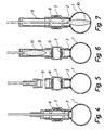
- the reinforced inflatable device 10 can be inserted in the pipe 1 and be inflated by means of a pressurized fluid source associated therewith in such a manner that the passage through the pipe 1 has been shut off, cf. Fig. 8.
- the pressure is removed therefrom, cf. Fig. 9.
- the inflatable blocking device 10 can be removed and the shut-off valve 6 be shut off, and the device 9 can be removed, cf. Fig. 10.
- a device 11 can be screwed down at the end of the shut-off valve 6 for the insertion of a closure plug 12 into the pipe branch 3.
- This device 11 comprises a rotatable bar 14, and the closure plug 12 is loosely secured at the end of said bar 14.
- the closure plug 12 is of a diameter substantially corresponding to the internal diameter of the pipe branch 3.
- the closure plug 12 is made of a solid material with teflon tape and is secured to the bar 14 by means of a particular gripping member ensuring a non-rotatable connection between the bar 14 and the plug 12.
- the closure plug 12 can be screwed down into the internal thread of the pipe branch 3 by means of the rotatable bar 14.
- the gripping member and the rotatable bar 14 can be removed from the closure plug 12 whereafter the shut-off valve 6 and the device 11 can be dismounted, optionally in one step, cf. Fig. 13. Subsequently, it is possible to screw a cover 15 down on the pipe branch 3, said cover serving as an additional safety device.
- Seals in form of O-rings can advantageously be used in connection with the various interconnections by means of threads.
- interconnections can also be provided by means of couplings, such as bayonet clutches or the like devices.
- a particular advantage of the method according to the invention is that the valve can be removed after use and optionally reused elsewhere.
- the blocking method according to the invention facilitates an interference with and service on an existing pipe system without necessitating a previous emptying thereof.
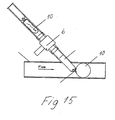
- the pipe branch is welded at an oblique angle relative to the pipe, cf. Fig. 15, and then the inflatable balloon 10 is obliquely inserted relative to the pipe.
- the balloon 10 does not come into contact with possible inner burrs at the interconnecting location of the pipe branch and the pipe.
- the balloon blocking mechanism can be shaped as shown in Fig. 16, wherein 21 is a gas-conducting hose communicating with a gas-conducting pipe 23 for the supply of high-pressure gas or pressurized fluid to a balloon 25 made of Kevlar-reinforced latex.
- the balloon 25 houses a spring system 24 for distending the balloon in the longitudinal direction and ensuring a correct folding up of the balloon 25.
Landscapes
- Engineering & Computer Science (AREA)
- General Engineering & Computer Science (AREA)
- Mechanical Engineering (AREA)
- Pipe Accessories (AREA)
- Processing Of Terminals (AREA)
Abstract
Description
Claims (6)
- A method of inserting an inflatable blocking device (10) into a pipe (1), whereby a pipe branch (3) is initially welded at the inserting location of the blocking device (10), said pipe branch being of a relatively small diameter, and followed by a mounting at the end of said pipe branch (3) of a shut-off valve (6), wherein one hole being drilled in the pipe wall (1) through said shut-off valve (6) and said pipe branch (3), whereafter a loosely suspended inflatable device (10) with reinforcing means is inserted through said shut-off valve (6) and said hole into the pipe (1) so as to block said pipe, and wherein the loosely suspended inflatable device (10) after use being removed through the valve (6), a shut-off member in form of a closure plug (12) being inserted also through the valve (6) into the pipe branch (3), where-after said valve member (6) can be removed, if desired, and wherein said loosely suspended inflatable device with the reinforcing means comprising a rod embedded in a balloon and surrounded by a resilient means.
- A method as claimed in claim 1, characterised in that the resilient means is embedded in the inflatable device.
- A method as claimed in claim 1 or 2, characterised in that the balloon is made of Kevlar optionally admixed latex.
- A method as claimed in one or more of the preceding claims, charised in that the pipe branch (3) is obliquely welded relative to the pipe (1), such as at an angle of approximately 45° relative thereto.
- A method as claimed in one or more of the preceding claims, characterised in that the pipe branch (3) is provided with an external thread (4) for the screwing down of a valve member (6).
- A method as claimed in one or more of the preceding claims, characterised in that the pipe branch (3) further comprises an internal thread for the screwing down and retaining of the closure plug (12).
Priority Applications (2)
| Application Number | Priority Date | Filing Date | Title |
|---|---|---|---|
| SI200030496T SI1198683T1 (en) | 1999-08-06 | 2000-08-04 | A method of closing a pipe |
| DK00951270T DK1198683T3 (en) | 2000-08-04 | 2000-08-04 | Method for closing a tube |
Applications Claiming Priority (3)
| Application Number | Priority Date | Filing Date | Title |
|---|---|---|---|
| DKPA199901103 | 1999-08-06 | ||
| DK110399 | 1999-08-06 | ||
| PCT/DK2000/000436 WO2001011283A2 (en) | 1999-08-06 | 2000-08-04 | A method of closing a pipe |
Publications (2)
| Publication Number | Publication Date |
|---|---|
| EP1198683A2 EP1198683A2 (en) | 2002-04-24 |
| EP1198683B1 true EP1198683B1 (en) | 2004-10-20 |
Family
ID=8101039
Family Applications (1)
| Application Number | Title | Priority Date | Filing Date |
|---|---|---|---|
| EP00951270A Expired - Lifetime EP1198683B1 (en) | 1999-08-06 | 2000-08-04 | A method of closing a pipe |
Country Status (6)
| Country | Link |
|---|---|
| EP (1) | EP1198683B1 (en) |
| AT (1) | ATE280353T1 (en) |
| AU (1) | AU6426600A (en) |
| DE (1) | DE60015136T2 (en) |
| ES (1) | ES2225189T3 (en) |
| WO (1) | WO2001011283A2 (en) |
Families Citing this family (4)
| Publication number | Priority date | Publication date | Assignee | Title |
|---|---|---|---|---|
| EP1365182A1 (en) | 2002-05-21 | 2003-11-26 | Keld Saxenfelt | An inflatable, flexible device |
| SI21516A (en) * | 2003-06-11 | 2004-12-31 | SAVATECH družba za proizvodnjo gumenotehničnih proizvodov | Pneumatic locking cap for pipelines, particularly gas pipelines |
| ITBS20050124A1 (en) * | 2005-10-20 | 2007-04-21 | Greiner Spa | FITTING DEVICE FOR CONNECTING A DERIVATION TO A FLUID TRANSPORT CONDUCT |
| GB2486244A (en) * | 2010-12-09 | 2012-06-13 | William Peter Allen | Temporary stopcock |
Family Cites Families (2)
| Publication number | Priority date | Publication date | Assignee | Title |
|---|---|---|---|---|
| GB2132309B (en) * | 1982-12-10 | 1986-11-19 | Roberts & Prowse Limited | Plugging pipes |
| SE501299C2 (en) * | 1993-05-26 | 1995-01-09 | Tigerholm Ab | Method for blocking pipelines and apparatus for carrying out the method |
-
2000
- 2000-08-04 AT AT00951270T patent/ATE280353T1/en active
- 2000-08-04 EP EP00951270A patent/EP1198683B1/en not_active Expired - Lifetime
- 2000-08-04 AU AU64266/00A patent/AU6426600A/en not_active Abandoned
- 2000-08-04 ES ES00951270T patent/ES2225189T3/en not_active Expired - Lifetime
- 2000-08-04 WO PCT/DK2000/000436 patent/WO2001011283A2/en not_active Ceased
- 2000-08-04 DE DE60015136T patent/DE60015136T2/en not_active Expired - Lifetime
Also Published As
| Publication number | Publication date |
|---|---|
| WO2001011283A3 (en) | 2001-07-05 |
| DE60015136T2 (en) | 2005-10-13 |
| EP1198683A2 (en) | 2002-04-24 |
| AU6426600A (en) | 2001-03-05 |
| ES2225189T3 (en) | 2005-03-16 |
| DE60015136D1 (en) | 2004-11-25 |
| ATE280353T1 (en) | 2004-11-15 |
| WO2001011283A2 (en) | 2001-02-15 |
Similar Documents
| Publication | Publication Date | Title |
|---|---|---|
| CA2704427C (en) | Double block and bleed plug | |
| US6161563A (en) | Plumbing tool | |
| JP5507571B2 (en) | Improved double block and fluid discharge plug | |
| US4649948A (en) | Entry tap valve for pressurized pipe leak detector | |
| US5904377A (en) | Pipe fitting | |
| US4351349A (en) | Pipe repair kit apparatus and method | |
| US4680848A (en) | Pipe tapping tool | |
| JPH02501155A (en) | Method and apparatus for attaching objects within fluid containing conduits | |
| US7886773B2 (en) | Low pressure directional stop bypass device | |
| US5199145A (en) | Corporate stop assembly | |
| US5285806A (en) | Method and apparatus for temporarily sealing off pipelines | |
| US5396814A (en) | Method of hot tapping a pipe for installing ionic flowmeter transducers | |
| US3774646A (en) | Line stopping assembly using an inflatable element | |
| EP1198683B1 (en) | A method of closing a pipe | |
| US20080260466A1 (en) | Apparatus for permitting access to the interior of a subterranean fluid-carrying pipe by way of an excavation which has uncovered the wall of the pipe | |
| US20190376632A1 (en) | Under-pressure tapping and access assembly for pressurized pipe | |
| US6126369A (en) | Hot tap tool | |
| US6553842B1 (en) | Pressurization test adapter | |
| JP5911413B2 (en) | Renewal method of fluid piping system using fluid pipe unit | |
| WO2011098774A1 (en) | Pipe seal | |
| US20060070659A1 (en) | Method and apparatus for installation of a flow control valve for mounting a subterraneously positioned pipe | |
| JPH03177697A (en) | Water cut-off device and bag thereof | |
| JPH02599B2 (en) | ||
| GB2448375A (en) | G clamp tapping fitting | |
| EP2685147B1 (en) | Top-piece device with position indicator |
Legal Events
| Date | Code | Title | Description |
|---|---|---|---|
| PUAI | Public reference made under article 153(3) epc to a published international application that has entered the european phase |
Free format text: ORIGINAL CODE: 0009012 |
|
| 17P | Request for examination filed |
Effective date: 20011128 |
|
| AK | Designated contracting states |
Kind code of ref document: A2 Designated state(s): AT BE CH CY DE DK ES FI FR GB GR IE IT LI LU MC NL PT SE |
|
| AX | Request for extension of the european patent |
Free format text: AL PAYMENT 20011128;LT PAYMENT 20011128;LV PAYMENT 20011128;MK PAYMENT 20011128;RO PAYMENT 20011128;SI PAYMENT 20011128 |
|
| RAP1 | Party data changed (applicant data changed or rights of an application transferred) |
Owner name: TRE-FOR ENTREPRISE A/S |
|
| 17Q | First examination report despatched |
Effective date: 20030602 |
|
| GRAP | Despatch of communication of intention to grant a patent |
Free format text: ORIGINAL CODE: EPIDOSNIGR1 |
|
| GRAS | Grant fee paid |
Free format text: ORIGINAL CODE: EPIDOSNIGR3 |
|
| GRAA | (expected) grant |
Free format text: ORIGINAL CODE: 0009210 |
|
| AK | Designated contracting states |
Kind code of ref document: B1 Designated state(s): AT BE CH CY DE DK ES FI FR GB GR IE IT LI LU MC NL PT SE |
|
| AX | Request for extension of the european patent |
Extension state: AL LT LV MK RO SI |
|
| REG | Reference to a national code |
Ref country code: GB Ref legal event code: FG4D |
|
| REG | Reference to a national code |
Ref country code: SE Ref legal event code: TRGR |
|
| REG | Reference to a national code |
Ref country code: CH Ref legal event code: EP Ref country code: CH Ref legal event code: NV Representative=s name: PATENTANWALTSBUERO EDER AG |
|
| REG | Reference to a national code |
Ref country code: DK Ref legal event code: T3 |
|
| REG | Reference to a national code |
Ref country code: IE Ref legal event code: FG4D |
|
| REF | Corresponds to: |
Ref document number: 60015136 Country of ref document: DE Date of ref document: 20041125 Kind code of ref document: P |
|
| REG | Reference to a national code |
Ref country code: SI Ref legal event code: IF |
|
| PG25 | Lapsed in a contracting state [announced via postgrant information from national office to epo] |
Ref country code: GR Free format text: LAPSE BECAUSE OF FAILURE TO SUBMIT A TRANSLATION OF THE DESCRIPTION OR TO PAY THE FEE WITHIN THE PRESCRIBED TIME-LIMIT Effective date: 20050120 |
|
| REG | Reference to a national code |
Ref country code: ES Ref legal event code: FG2A Ref document number: 2225189 Country of ref document: ES Kind code of ref document: T3 |
|
| ET | Fr: translation filed | ||
| PG25 | Lapsed in a contracting state [announced via postgrant information from national office to epo] |
Ref country code: LU Free format text: LAPSE BECAUSE OF NON-PAYMENT OF DUE FEES Effective date: 20050804 Ref country code: CY Free format text: LAPSE BECAUSE OF FAILURE TO SUBMIT A TRANSLATION OF THE DESCRIPTION OR TO PAY THE FEE WITHIN THE PRESCRIBED TIME-LIMIT Effective date: 20050804 |
|
| PLBE | No opposition filed within time limit |
Free format text: ORIGINAL CODE: 0009261 |
|
| STAA | Information on the status of an ep patent application or granted ep patent |
Free format text: STATUS: NO OPPOSITION FILED WITHIN TIME LIMIT |
|
| PG25 | Lapsed in a contracting state [announced via postgrant information from national office to epo] |
Ref country code: MC Free format text: LAPSE BECAUSE OF NON-PAYMENT OF DUE FEES Effective date: 20050831 |
|
| 26N | No opposition filed |
Effective date: 20050721 |
|
| PG25 | Lapsed in a contracting state [announced via postgrant information from national office to epo] |
Ref country code: PT Free format text: LAPSE BECAUSE OF NON-PAYMENT OF DUE FEES Effective date: 20050320 |
|
| PGFP | Annual fee paid to national office [announced via postgrant information from national office to epo] |
Ref country code: CH Payment date: 20110816 Year of fee payment: 12 Ref country code: IE Payment date: 20110824 Year of fee payment: 12 Ref country code: DK Payment date: 20110825 Year of fee payment: 12 |
|
| PGFP | Annual fee paid to national office [announced via postgrant information from national office to epo] |
Ref country code: GB Payment date: 20110831 Year of fee payment: 12 Ref country code: SE Payment date: 20110824 Year of fee payment: 12 Ref country code: AT Payment date: 20110829 Year of fee payment: 12 Ref country code: ES Payment date: 20110823 Year of fee payment: 12 Ref country code: DE Payment date: 20110829 Year of fee payment: 12 Ref country code: FR Payment date: 20110908 Year of fee payment: 12 Ref country code: FI Payment date: 20110818 Year of fee payment: 12 |
|
| PGFP | Annual fee paid to national office [announced via postgrant information from national office to epo] |
Ref country code: NL Payment date: 20110831 Year of fee payment: 12 Ref country code: IT Payment date: 20110822 Year of fee payment: 12 Ref country code: BE Payment date: 20110825 Year of fee payment: 12 |
|
| BERE | Be: lapsed |
Owner name: *TRE-FOR ENTREPRISE A/S Effective date: 20120831 |
|
| REG | Reference to a national code |
Ref country code: NL Ref legal event code: V1 Effective date: 20130301 |
|
| REG | Reference to a national code |
Ref country code: LT Ref legal event code: MM9D Effective date: 20120804 |
|
| REG | Reference to a national code |
Ref country code: CH Ref legal event code: PL |
|
| REG | Reference to a national code |
Ref country code: SE Ref legal event code: EUG Ref country code: DK Ref legal event code: EBP |
|
| REG | Reference to a national code |
Ref country code: AT Ref legal event code: MM01 Ref document number: 280353 Country of ref document: AT Kind code of ref document: T Effective date: 20120804 |
|
| GBPC | Gb: european patent ceased through non-payment of renewal fee |
Effective date: 20120804 |
|
| PG25 | Lapsed in a contracting state [announced via postgrant information from national office to epo] |
Ref country code: FI Free format text: LAPSE BECAUSE OF NON-PAYMENT OF DUE FEES Effective date: 20120804 Ref country code: CH Free format text: LAPSE BECAUSE OF NON-PAYMENT OF DUE FEES Effective date: 20120831 Ref country code: LI Free format text: LAPSE BECAUSE OF NON-PAYMENT OF DUE FEES Effective date: 20120831 Ref country code: NL Free format text: LAPSE BECAUSE OF NON-PAYMENT OF DUE FEES Effective date: 20130301 Ref country code: SE Free format text: LAPSE BECAUSE OF NON-PAYMENT OF DUE FEES Effective date: 20120805 |
|
| REG | Reference to a national code |
Ref country code: SI Ref legal event code: KO00 Effective date: 20130306 |
|
| REG | Reference to a national code |
Ref country code: FR Ref legal event code: ST Effective date: 20130430 |
|
| REG | Reference to a national code |
Ref country code: IE Ref legal event code: MM4A |
|
| PG25 | Lapsed in a contracting state [announced via postgrant information from national office to epo] |
Ref country code: IT Free format text: LAPSE BECAUSE OF NON-PAYMENT OF DUE FEES Effective date: 20120804 Ref country code: BE Free format text: LAPSE BECAUSE OF NON-PAYMENT OF DUE FEES Effective date: 20120831 |
|
| PG25 | Lapsed in a contracting state [announced via postgrant information from national office to epo] |
Ref country code: AT Free format text: LAPSE BECAUSE OF NON-PAYMENT OF DUE FEES Effective date: 20120804 |
|
| PG25 | Lapsed in a contracting state [announced via postgrant information from national office to epo] |
Ref country code: DK Free format text: LAPSE BECAUSE OF NON-PAYMENT OF DUE FEES Effective date: 20120831 Ref country code: GB Free format text: LAPSE BECAUSE OF NON-PAYMENT OF DUE FEES Effective date: 20120804 Ref country code: DE Free format text: LAPSE BECAUSE OF NON-PAYMENT OF DUE FEES Effective date: 20130301 Ref country code: IE Free format text: LAPSE BECAUSE OF NON-PAYMENT OF DUE FEES Effective date: 20120804 |
|
| PG25 | Lapsed in a contracting state [announced via postgrant information from national office to epo] |
Ref country code: FR Free format text: LAPSE BECAUSE OF NON-PAYMENT OF DUE FEES Effective date: 20120831 |
|
| REG | Reference to a national code |
Ref country code: DE Ref legal event code: R119 Ref document number: 60015136 Country of ref document: DE Effective date: 20130301 |
|
| REG | Reference to a national code |
Ref country code: ES Ref legal event code: FD2A Effective date: 20131030 |
|
| PG25 | Lapsed in a contracting state [announced via postgrant information from national office to epo] |
Ref country code: ES Free format text: LAPSE BECAUSE OF NON-PAYMENT OF DUE FEES Effective date: 20120805 |