EP1198156A2 - Access network with alternate controller and line concentrator for handling connection requests (calls) exceeding the maximum line capacity of the network - Google Patents
Access network with alternate controller and line concentrator for handling connection requests (calls) exceeding the maximum line capacity of the network Download PDFInfo
- Publication number
- EP1198156A2 EP1198156A2 EP01102838A EP01102838A EP1198156A2 EP 1198156 A2 EP1198156 A2 EP 1198156A2 EP 01102838 A EP01102838 A EP 01102838A EP 01102838 A EP01102838 A EP 01102838A EP 1198156 A2 EP1198156 A2 EP 1198156A2
- Authority
- EP
- European Patent Office
- Prior art keywords
- alternate
- line
- subscriber
- concentrator
- access network
- Prior art date
- Legal status (The legal status is an assumption and is not a legal conclusion. Google has not performed a legal analysis and makes no representation as to the accuracy of the status listed.)
- Withdrawn
Links
Images





Classifications
-
- H—ELECTRICITY
- H04—ELECTRIC COMMUNICATION TECHNIQUE
- H04Q—SELECTING
- H04Q11/00—Selecting arrangements for multiplex systems
- H04Q11/04—Selecting arrangements for multiplex systems for time-division multiplexing
-
- H—ELECTRICITY
- H04—ELECTRIC COMMUNICATION TECHNIQUE
- H04J—MULTIPLEX COMMUNICATION
- H04J2203/00—Aspects of optical multiplex systems other than those covered by H04J14/05 and H04J14/07
- H04J2203/0001—Provisions for broadband connections in integrated services digital network using frames of the Optical Transport Network [OTN] or using synchronous transfer mode [STM], e.g. SONET, SDH
- H04J2203/0028—Local loop
- H04J2203/0039—Topology
- H04J2203/0041—Star, e.g. cross-connect, concentrator, subscriber group equipment, remote electronics
-
- H—ELECTRICITY
- H04—ELECTRIC COMMUNICATION TECHNIQUE
- H04J—MULTIPLEX COMMUNICATION
- H04J2203/00—Aspects of optical multiplex systems other than those covered by H04J14/05 and H04J14/07
- H04J2203/0001—Provisions for broadband connections in integrated services digital network using frames of the Optical Transport Network [OTN] or using synchronous transfer mode [STM], e.g. SONET, SDH
- H04J2203/0028—Local loop
- H04J2203/0039—Topology
- H04J2203/0042—Ring
-
- H—ELECTRICITY
- H04—ELECTRIC COMMUNICATION TECHNIQUE
- H04J—MULTIPLEX COMMUNICATION
- H04J2203/00—Aspects of optical multiplex systems other than those covered by H04J14/05 and H04J14/07
- H04J2203/0001—Provisions for broadband connections in integrated services digital network using frames of the Optical Transport Network [OTN] or using synchronous transfer mode [STM], e.g. SONET, SDH
- H04J2203/0046—User Network Interface
- H04J2203/0048—Network termination, e.g. NT1, NT2, PBX
-
- H—ELECTRICITY
- H04—ELECTRIC COMMUNICATION TECHNIQUE
- H04J—MULTIPLEX COMMUNICATION
- H04J2203/00—Aspects of optical multiplex systems other than those covered by H04J14/05 and H04J14/07
- H04J2203/0001—Provisions for broadband connections in integrated services digital network using frames of the Optical Transport Network [OTN] or using synchronous transfer mode [STM], e.g. SONET, SDH
- H04J2203/0064—Admission Control
- H04J2203/0067—Resource management and allocation
-
- H—ELECTRICITY
- H04—ELECTRIC COMMUNICATION TECHNIQUE
- H04Q—SELECTING
- H04Q2213/00—Indexing scheme relating to selecting arrangements in general and for multiplex systems
- H04Q2213/13166—Fault prevention
-
- H—ELECTRICITY
- H04—ELECTRIC COMMUNICATION TECHNIQUE
- H04Q—SELECTING
- H04Q2213/00—Indexing scheme relating to selecting arrangements in general and for multiplex systems
- H04Q2213/13167—Redundant apparatus
-
- H—ELECTRICITY
- H04—ELECTRIC COMMUNICATION TECHNIQUE
- H04Q—SELECTING
- H04Q2213/00—Indexing scheme relating to selecting arrangements in general and for multiplex systems
- H04Q2213/13298—Local loop systems, access network
-
- H—ELECTRICITY
- H04—ELECTRIC COMMUNICATION TECHNIQUE
- H04Q—SELECTING
- H04Q2213/00—Indexing scheme relating to selecting arrangements in general and for multiplex systems
- H04Q2213/13386—Line concentrator
Definitions
- the present invention relates to an access network, and in particular to an access network having a maximum line capacity of connectable subscriber calls prescribed.
- a maximum line capacity of connectable subscriber calls has been prescribed based on a capacity of a link (interface) for connecting a plurality of subscriber lines or circuits to the local exchange. For this reason, it is important to efficiently make use of a limited line capacity and to attend to a connection demand from the subscriber.
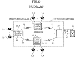
- Fig.10 shows an example of a prior art access network, in which an access network 100 is connected to a local exchange 50 with V5.2 protocol (interface) (hereinafter, occasionally abbreviated as V5 protocol).
- V5.2 protocol interface
- V5 protocol V5 protocol
- the access network 100 has an SDH (Synchronous Digital Hierarchy) ring network arrangement in which a central terminal 30 and remote terminals 10_1-10_3 are sequentially connected with optical transmission lines 21-24.
- SDH Serial Digital Hierarchy
- the remote terminals 10_1, 10_2, and 10_3 are respectively equipped with a V5 concentrator 13, and accommodate telephones (hereinafter, referred to as terminals) 1_1-1_i (hereinafter, sometimes generally represented by reference numeral 1), terminals 2_1-2_j (hereinafter, sometimes generally represented by reference numeral 2), and terminals 3_1-3_k.
- Fig.11 shows a more detailed arrangement of the access network 100 in Fig.10.
- the remote terminal 10_3 shown in Fig.10 is omitted for convenience' sake.
- Each remote terminal 10 is composed of the concentrator 13, a trunk 17 connected to the concentrator 13, and a controller 16.
- the central terminal 30 is composed of a trunk 32 and a controller 35.
- the trunk 32 in the central terminal 30 is connected to the local exchange 50 with link groups 41 and 42. Also, the trunk 32 in the central terminal 30, the trunks 17 in the remote terminals 10_1 and 10_2 are physically connected ringlike to an active optical transmission line which transmits an STM-1 signal counterclockwise and to a standby transmission line which transmits the STM-1 signal clockwise.
- Fig.11 shows a connection of these transmission lines at a level of path.
- the trunk 17 in the remote terminal 10_1 is connected to the trunk 32 in the central terminal 30 in an active path group 21_1 and a standby path group 22_1 (and path group 23_1 same as the path group 22_1)
- the trunk 17 in the remote terminal 10_2 is connected to the trunk 32 in an active path group 22_2 (and path group 21_2 same as the path group 22_2) and a standby path group 23_2.
- the concentrators 13 in the remote terminals 10_1 and 10_2 respectively accommodate 400 terminals 1_1-1_400 and 500 terminals 2_1-2_500.
- the terminal 1 accommodated in the remote terminal 10_1 is connected to the local exchange 50 through the concentrator 13, the trunk 17, the active path 21_1, the trunk 32, and the link group 41.
- the terminal 2 accommodated in the remote terminal 10_2 is connected to the local exchange 50 through the concentrator 13, the trunk 17, the active paths 22_2 and 21_2, the trunk 32, and the link group 42.
- the terminal 1 In case that a fault occurs on the active path 21_1 at present, the terminal 1 is connected to the local exchange 50 through the concentrator 13, the trunk 17, the standby paths 22_1 and 23_1, the trunk 32, and the link group 41. Similarly, in case that a fault occurs on the active path 22_2 or 21_2, the terminal 2 is connected to the local exchange 50 through the concentrator 13, the trunk 17, the standby path 23_2, the trunk 32, and the link group 42.
- two or three links are respectively allocated to the remote terminals 10_1 and 10_2, and these link groups are assumed to be the link groups 41 (2 Mbps ⁇ 2) and 42 (2 Mbps ⁇ 3) in Fig.11.
- the transmission capacity of the active path 21_1 and the standby paths 22_1 and 23_1 is 2 Mbps ⁇ 2, and that of the active paths 21_2 and 22_2 and the standby path 23_2 is 2 Mbps ⁇ 3.
- the maximum number of terminals which can be synchronously connected is "60" in the 400 accommodated terminals 1
- the maximum number of terminals which can be synchronously connected is "90" in the 500 accommodated terminals 2.
- the call number in commercial buildings or the like increases in a limited time zone from morning till evening, and extremely decreases in a time zone after the evening.
- transmission lines corresponding to the maximum number of calls have to be prepared in spite of a large change in the number of calls depending on the time zone, resulting in a bad working efficiency or availability.
- an access network of the present invention comprises : a remote terminal including a subscriber concentrator having a maximum number of connectable subscriber calls prescribed, a congestion detector for detecting whether or not the subscriber calls received by the subscriber concentrator exceed the maximum number causing congestion, and an alternate controller for setting up an empty line as an alternate line when the congestion detector detects the congestion state, and a central terminal including an alternate line concentrator for concentrating the alternate line.
- Fig.1 shows a principle of an access network according to the present invention.
- the controller 16 shown in Fig.11 is omitted for convenience' sake.
- a subscriber concentrator 13 prescribes or defines e.g. "90" for the maximum number of connectable calls.
- the subscriber concentrator 13 connects calls of subscribers (hereinafter referred to also as terminals) 2_1-2_90, for example, and when a congestion state occurs due to a further connection demand of a terminal 2_91, a congestion detector (not shown) detects the congestion state.
- An alternate controller (not shown) which has received the notification of the congestion state from the congestion detector sets up an alternate line through e.g. an empty standby path 23_2, and connects the call of e.g. the above-mentioned terminal 2_91 with the alternate line (see mark in Fig.1).
- an alternate line concentrator 33 takes out the alternate line from the path 23_2 to be concentrated.
- the remote terminal 10_2 it becomes possible for the remote terminal 10_2 to connect calls exceeding the maximum number of connectable calls "90" by making e.g. a standby line an alternate line. In turn, it becomes possible to raise a working efficiency of a transmission line. It is to be noted that not only a standby line but also an empty line unused in the access network can be used for an alternate line.
- the congestion detector when detecting that a predetermined number of calls can not be received within a predetermined time, the congestion detector may determine the congestion state.
- the congestion detector detects the state in which the number of calls which the subscriber concentrator has been unable to receive for a predetermined time e.g. 20 minutes exceeds 10 as the congestion state, and notifies the alternate controller of the congestion state.
- the alternate controller sets up an alternate line to perform a call connection.
- the alternate line concentrator in the central terminal may be connected to a local exchange with a link of a predetermined line capacity, and the alternate controller may notify the local exchange of the congestion state whereby the local exchange may use a predetermined alternate link which connects the local exchange and the alternate line concentrator.
- the alternate controller of the remote terminal 10 notifies the local exchange 50 of the congestion state.
- the local exchange 50 recognizes the notification and uses a predetermined empty link between the local exchange and the alternate line concentrator.
- the alternate controller may have a subscriber priority order management table for indicating a priority order of a subscriber call connected to the alternate line.
- a subscriber using an alternate line is preset in a management table. Namely, a less important subscriber is predetermined to be preferentially passed to the alternate line.
- the alternate controller selects the subscriber call to be switched over to the alternate line based on the priority order of the management table to be connected to the alternate line.
- all of the remote terminals may make a line predetermined as the empty line an alternate line.
- the remote terminal 10_1 and 10_2 assumes a congestion state
- all of the remote terminals 10 connect the subscriber calls which the management table designates to the alternate line.
- the alternate controller when there is an empty active line or an empty standby line, the alternate controller may set up the empty line as the alternate line. Thus, it becomes possible to raise the working efficiency of the transmission line.
- the alternate controller of the remote terminal 10 notifies the alternate line concentrator 33 in the central terminal 30 of the congestion state.
- the alternate controller and the alternate line concentrator 33 may use the alternate line predetermined as the empty line.
- the alternate line concentrator may have a management table indicating a correspondence between the subscriber calls and a link which concentrates the calls, and the subscriber calls from the alternate lines may be concentrated to a single or a plurality of predetermined links based on the management table.
- the concentration operation of the alternate line concentrator becomes easier to be dealt with compared with the case where the link which connects the subscriber call is not determined, and it becomes possible to specify the link to which the subscriber call is connected, resulting in an easier maintenance management.
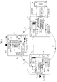
- FIG.1 An embodiment (1) of an access network 100 according to the present invention schematically shown in Fig.1 will now be described referring to Fig.2. While the basic arrangement of the network is the same as that of the prior art ring access network shown in Fig.11, the access network of the present invention can be applied to a connection form not only of a ring type network, but also a star type network or the like.
- the access network of the present invention is different from the prior art access network in the internal arrangements of the remote terminal 10 and the central terminal 30.
- the remote terminal 10_1 includes a channel (CH) card 11 accommodating terminals 1_1-1_400, an alternate circuit 14 and a V5 concentrator 13 commonly connected to the card 11 with a bus 12, an optical unit 18_1 connected to the alternate circuit 14 and the V5 concentrator 13 with a trunk 17_1, and a congestion detector 19 which detects the congestion state of the concentrator 13 to be notified to an alternate controller 15.
- CH channel
- the remote terminal 10_1 includes a channel (CH) card 11 accommodating terminals 1_1-1_400, an alternate circuit 14 and a V5 concentrator 13 commonly connected to the card 11 with a bus 12, an optical unit 18_1 connected to the alternate circuit 14 and the V5 concentrator 13 with a trunk 17_1, and a congestion detector 19 which detects the congestion state of the concentrator 13 to be notified to an alternate controller 15.
- CH channel
- the alternate controller 15 controls the alternate circuit 14 for setting up an alternate line when a congestion state occurs, the V5 concentrator 13, and the optical unit 18_1.
- the remote terminal 10_1 is equipped with a trunk 17_2 and an optical unit 18_2 for using a part of an optical transmission line 22 as a standby line.
- the arrangement of the remote terminal 10_2 is the same as that of the remote terminal 10_1.
- the central terminal 30 includes an optical unit 31_1 for accommodating a transmission line 21, an E1 unit 36 connected to the optical unit 31_1 with a trunk 32_1, an alternate line concentrator 33 which concentrates alternate lines from the optical unit 31_1 to be connected to the E1 unit 36, and a concentration controller 34 for controlling the concentrator 33. Furthermore, the central terminal 30 is equipped with an optical unit 31_2 for accommodating a standby transmission line 23 and a trunk 32_2 connected to the optical unit 31_2.
- the local exchange 50 is connected to the central terminal 30 with the link groups 41 and 42 accommodated in the E1 unit 36, and the alternate link group 43.
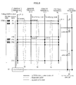
- Fig.3 shows a connection state of the optical units 18_1 and 18_2 (generally represented by reference numeral 18 in Fig.3) in the remote terminals 10_1 and 10_2, the optical units 31_1 and 31_2 in the central terminal 30, and the transmission lines 21-23 composed of standby transmission lines and active transmission lines.
- the path of the active transmission line is shown by a solid line and the path of the standby transmission line is shown by a dashed line in Fig.3. Also, the same reference numeral is used for the paths of both active and standby transmission lines. Moreover, the same central terminal 30 is shown at 2 portions in Fig.3 for convenience' sake.
- the transmission lines 21-23 mutually connects the optical units 18_1, 18_2, and 31_1 with STM-1 (Synchronous Transport Module-1) interface of 155.52 Mbps which is the basic transmission rate.
- STM-1 Synchronous Transport Module-1
- 7 active paths P1-P5, P62, and P63 of 2 Mbps paths (line bundle) included in the STM-1 interface are used.
- the alternate lines are set up along the paths P62 and P63 of those 7 paths.
- the optical unit 18_1 in the remote terminal 10_1 is connected to the optical unit 31_1 in the central terminal 30 through the paths P4 and P5 (solid line parts) of the active transmission line 21, while the optical unit 18_2 is connected to the optical unit 31_2 through the paths P4 and P5 (dashed line parts) of the transmission lines 22 and 23.
- the optical unit 18_1 in the remote terminal 10_2 is connected to the optical unit 31_1 through the paths P1-P3 (solid line parts) of the active transmission lines 21 and 22, while the optical unit 18_2 is connected to the optical unit 31_2 through the paths P1-P3 (dashed line parts) of the standby transmission line 23.
- the alternate controller 15 in the remote terminal 10_1 connects the subscriber call to the central terminal 30 by using the line included in the active path P62 as an alternate line.
- the concentrator 33 in the central terminal 30 is connected to the local exchange 50 with the alternate link 43 which concentrates the alternate lines.
- the subscriber call of the remote terminal 10_2 is similarly connected to the local exchange 50 through the alternate line included in the active path P63, the concentrator 33, and the alternate link 43.
- the V5 concentrator 13 in the remote terminal 10_1 can select the subscriber calls from 60 terminals among the terminals 1_1-1_400 through the card 11 and the bus 12, and can connect the selected subscriber call to the optical unit 18_1 through the trunk 17_1.
- This connected subscriber call is connected to the central terminal 30 through the active paths P4 and P5 (each 30 lines, and 60 lines in total).
- the V5 concentrator 13 in the remote terminal 10_2 selects the subscriber calls from 90 terminals among the terminals 2_1-2_500, and connects the selected subscriber call to the optical unit 18_1, so that this connected subscriber call is connected to the central terminal 30 through the active paths P1-P3 (each 30 lines, and 90 lines in total).
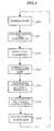
- Fig.4 shows an example of an operation procedure of the access network 100 of the present invention shown in Fig.2. Hereinafter, the operation procedure will be described.
- the concentrator 33 in the central terminal 30 releases the alternate link 43 between the central terminal 30 and the local exchange 50.
- each remote terminal 10 independently connects the call to the alternate line in the above-mentioned operation procedure. However, if the alternate lines are simultaneously connected to all of the remote terminals 10 when the congestion state is detected in at least one of the remote terminals 10, the control operations in the remote terminals 10, the central terminal 30, and the local exchange 50 become easy.
- the functions of the V5 concentrator 13, the alternate circuit 14, the alternate controller 15, and the congestion detector 19 in the remote terminal 10 shown in Fig.2 can be respectively realized by a call allocation function, a call allocation control function, and a monitoring function.
- the V5 concentrator 13 and the alternate circuit 14 compose a call allocator 27, and the allocation controller 15 and the congestion detector 19 compose a call allocation controller/monitor 28 for convenience' sake.
- the call allocation controller/monitor 28 (congestion detector 19 therein) monitors the number of calls connected to the active lines and a call connection demand from the terminal. When receiving the call connection demand in a range not exceeding the maximum number of connectable calls, the call allocation controller/monitor 28 instructs the call allocator 27 to allocate the calls to the active lines. When receiving the call connection demand exceeding the maximum number of calls, the call allocation controller/monitor 28 sets up alternate lines and instructs the call allocator 27 to connect the calls through the alternate lines.
- Table 1 shows a threshold value example of a congested call detection by which the call allocation controller/monitor 28 determines the congestion state.
- the call allocation controller/monitor 28 determines it to be the congestion state when the call connection demand exceeding the maximum number of calls occurs more than "20 times" for 10 minutes guard time.
- Fig.6 is a sequence diagram showing a setup operation of an alternate line at the time of detecting the congestion state.
- the congestion detector 19 in the remote terminal 10 shown in Fig.2 sends notification signals 81 and 82 respectively indicating that the congestion state has occurred to the central terminal 30 and the local exchange 50 directly or through the alternate controller 15.
- the central terminal 30 and the local exchange 50 respectively receive the notification signals 81 and 82 to return reception notification signals 83 and 84.
- the remote terminal 10, the central terminal 30, and the local exchange 50 set up the alternate line (alternate link) after several hundreds of milliseconds guard time all at once to connect the call.
- Fig.7 shows subscriber priority order management tables 25, 26, and 37 respectively held by the alternate controller 15 in the remote terminal 10_1, the alternate controller 15 in the remote terminal 10_2, and the concentrator 33 in the central terminal 30.
- management tables 25, 26, and 37 are composed of "concentrator identifier V5ID”, "L3 address” of each terminal (subscriber) , and "alternate group flag” indicating whether or not the corresponding terminal should be connected to the alternate line.
- management table 37 prepares the management table 25 and adds the management table 26, thereby designating the terminals connected to the alternate lines concentrated to the concentrator 33 and the priority order of the terminals.
- L3 addresses are newly and sequentially added to the lines of the alternate link concentrated by the concentrator 33.
- the management table 37 shown in Fig.7 shows the case where the alternate lines (subscriber calls) concentrated from the remote terminals 10 are concentrated to a single link.
- the correspondence between each alternate line (identifier V5ID and L3 address) and the alternate link identifier which concentrates alternate lines can be indicated by adding, for example, the field of the alternate link identifier V5ID to the management table 37.
- the alternate controller 15 in the remote terminal 10_1 for example, notifies the central terminal 30 and the local exchange 50 of the congestion state when it occurs.
- the alternate controller 15 controls the concentrator 13 and the alternate circuit 14 so as to remove the subscriber connected to the alternate line from the V5 concentrator 13 and to switch it over to the alternate line side, by referring to the management table 25, after a predetermined time (guard time) has elapsed.
- the concentrator 33 in the central terminal 30 After receiving the congestion state notification from the remote terminal 10_1, the concentrator 33 in the central terminal 30 sets up the predetermined alternate link group 43 by referring to the management table 37 after a predetermined time has elapsed, and then concentrates the alternate lines from the remote terminals 10 to be connected to the local exchange 50 through the alternate link group 43.
- Fig.8 shows an embodiment (2) of an access network 100 of the present invention.
- the case has been described where when there is an empty active path an alternate line is set up along the empty active path.
- the operation example will be described in which when there is no empty active path an alternate line is set up along a standby path.
- Fig.9 shows a connection state of the optical unit 18 in each remote terminal 10, the optical units 31_1 and 31_2 in the central terminal 30, and the transmission lines 21-23 in the same way as Fig.3.
- connection state is different from the connection state of Fig.3 in that all of the active paths P1 P64 (only solid line parts) are used, and there is no empty path.
- the remote terminals 10_1 and 10_2 respectively use the active paths P1-P30 and P31-P63 (solid line parts), and there is no empty path.
- lines included in standby paths P1 and P2 are predetermined as alternate lines between the remote terminal 10_1 and the central terminal 30 and lines included in standby paths P31 and P32 (only dashed line parts) are predetermined as alternate lines between the remote terminal 10_2 and the central terminal 30.
- the call of a predetermined subscriber is connected to the central terminal 30 through the alternate line, so that the concentrator 33 in the central terminal 30 concentrates the alternate lines from the remote terminals to the alternate link group 43 to be connected to the local exchange 50.
- the remote terminal 10_1 accommodates 2000 terminals 1_1-1_ 2000.
- the remote terminal 10_2 accommodates 2000 terminals 2_1-2_2000, and the active paths P31-P63 (shown by solid lines in Fig.9) are prepared, so that simultaneous calls of 990 (33 paths ⁇ 30 lines) terminals can be performed.
- standby paths P1-P30 and P31-P63 (shown by dashed lines in Fig.9) reverse in direction to the active paths are set up along the remote terminals 10_1 and 10_2.
- the lines included in the standby paths P1 and P2 as well as P31 and P32 generally unused are set up as the alternate lines when the congestion state occurs.
- the concentrator 33 concentrates the alternate lines from the standby paths P1, P2, P31, and P32 to be connected to the local exchange as the alternate link group 43.
- the embodiment (2) can attend to the connection demand of the subscriber call exceeding the maximum number of calls.
- an access network is arranged such that when a congestion detector detects that a maximum number of subscriber calls which a subscriber concentrator can receive is exceeded to cause congestion, an alternate controller in a remote terminal sets up e.g. an empty active line or standby line as an alternate line, and an alternate line concentrator in a central terminal concentrates the alternate lines. Therefore, it is possible to attend to a connection demand of subscriber calls in excess of the maximum line capacity of the subscriber concentrator.
- the alternate controller is arranged so as to select a subscriber call to be connected to the alternate line based on a subscriber priority order management table. Therefore, it becomes possible for a more important subscriber to reliably perform a communication through an active line without being connected to an alternate line. Namely it becomes possible to efficiently use a transmission line according to the importance degree and to suppress the cost of the transmission line.
- all of the remote terminals are arranged so as to make the line predetermined as the empty line an alternate line. Therefore, it becomes possible to efficiently use the transmission line according to a change of a call amount for a time zone, so that the control operation becomes easy.
Landscapes
- Engineering & Computer Science (AREA)
- Computer Networks & Wireless Communication (AREA)
- Sub-Exchange Stations And Push- Button Telephones (AREA)
- Use Of Switch Circuits For Exchanges And Methods Of Control Of Multiplex Exchanges (AREA)
- Data Exchanges In Wide-Area Networks (AREA)
- Monitoring And Testing Of Exchanges (AREA)
- Optical Communication System (AREA)
- Telephonic Communication Services (AREA)
Abstract
Description
| Type | Guard time (min) | Congestion call number (times) |
| 1 | 10 | 20 |
| 2 | 20 | 50 |
| 3 | 30 | 100 |
Claims (9)
- An access network comprising:a remote terminal including a subscriber concentrator having a maximum number of connectable subscriber calls prescribed, a congestion detector for detecting whether or not the subscriber calls received by the subscriber concentrator exceed the maximum number causing congestion, and an alternate controller for setting up an empty line as an alternate line when the congestion detector detects the congestion state, anda central terminal including an alternate line concentrator for concentrating the alternate line.
- The access network as claimed in claim 1 wherein when detecting that a predetermined number of calls cannot be received within a predetermined time, the congestion detector determines the congestion state.
- The access network as claimed inclaim 1 wherein the alternate line concentrator in the central terminal is connected to a local exchange with a link of a predetermined line capacity, and the alternate controller notifies the local exchange of the congestion state whereby the local exchange uses a predetermined alternate link which connects the local exchange and the alternate line concentrator.
- The access network as claimed in claim 1 wherein the alternate controller has a subscriber priority order management table for indicating a priority order of a subscriber call connected to the alternate line.
- The access network as claimed in claim 4 wherein when at least one of the remote terminals is in the congestion state, all of the remote terminals make a line predetermined as the empty line an alternate line.
- The access network as claimed in claim 1 wherein the empty line comprises an empty active line.
- The access network as claimed in claim 1 wherein the empty line comprises an empty standby line.
- The access network as claimed in claim 1 wherein the alternate controller notifies the alternate line concentrator of the congestion state, and uses a predetermined alternate line as the empty line.
- The access network as claimed in claim 3 wherein the alternate line concentrator has a management table for indicating a correspondence between subscriber calls from alternate lines and a link which concentrates the subscriber calls.
Applications Claiming Priority (2)
| Application Number | Priority Date | Filing Date | Title |
|---|---|---|---|
| JP2000313404A JP2002125040A (en) | 2000-10-13 | 2000-10-13 | Access network equipment |
| JP2000313404 | 2000-10-13 |
Publications (2)
| Publication Number | Publication Date |
|---|---|
| EP1198156A2 true EP1198156A2 (en) | 2002-04-17 |
| EP1198156A3 EP1198156A3 (en) | 2002-07-10 |
Family
ID=18792827
Family Applications (1)
| Application Number | Title | Priority Date | Filing Date |
|---|---|---|---|
| EP01102838A Withdrawn EP1198156A3 (en) | 2000-10-13 | 2001-02-13 | Access network with alternate controller and line concentrator for handling connection requests (calls) exceeding the maximum line capacity of the network |
Country Status (2)
| Country | Link |
|---|---|
| EP (1) | EP1198156A3 (en) |
| JP (1) | JP2002125040A (en) |
Family Cites Families (4)
| Publication number | Priority date | Publication date | Assignee | Title |
|---|---|---|---|---|
| GB8531138D0 (en) * | 1985-12-18 | 1986-01-29 | British Telecomm | Telecommunications network |
| JP3577348B2 (en) * | 1994-12-07 | 2004-10-13 | 富士通株式会社 | Variable length data exchange and variable length data terminal accommodated in the variable length data exchange |
| JP2968717B2 (en) * | 1996-04-25 | 1999-11-02 | 静岡日本電気株式会社 | Time division multiplex transmission equipment |
| SE507754C2 (en) * | 1996-10-10 | 1998-07-13 | Ericsson Telefon Ab L M | Method and device for network configuration at high load |
-
2000
- 2000-10-13 JP JP2000313404A patent/JP2002125040A/en not_active Withdrawn
-
2001
- 2001-02-13 EP EP01102838A patent/EP1198156A3/en not_active Withdrawn
Also Published As
| Publication number | Publication date |
|---|---|
| JP2002125040A (en) | 2002-04-26 |
| EP1198156A3 (en) | 2002-07-10 |
Similar Documents
| Publication | Publication Date | Title |
|---|---|---|
| EP0228204B1 (en) | Architecture for distributed control telecommunication switching systems | |
| EP0400879B1 (en) | Dynamic shared facility system for private networks | |
| CA1270958A (en) | Resource allocation in distributed control systems | |
| EP0307401B1 (en) | Method and apparatus for providing variable reliability in a telecommunication switching system | |
| JP2520997B2 (en) | Call processing method for distributed exchange | |
| UA54474C2 (en) | System and method to transfer a call trigger between communication networks | |
| USRE40398E1 (en) | ATM telecommunications systems and method for routing narrow band traffic | |
| CA2051070C (en) | Isdn d channel congestion control method | |
| US5537392A (en) | Procedure and device for routing telecommunications in a meshed network | |
| JPH09181718A (en) | Telecommunications network for servicing users from multiple exchanges | |
| US8547849B2 (en) | ATM telecommunications systems and method for routing narrow band traffic | |
| CA2159382C (en) | Single stage telecommunications switch with partitioned processors | |
| EP0696148B1 (en) | Communication system with queues and switching station therefor | |
| JP3681546B2 (en) | Subscriber transmission equipment with concentrating function | |
| US6618400B1 (en) | System for effectively using ISDN backup channel | |
| JP2002125040A (en) | Access network equipment | |
| JP3335686B2 (en) | Multi-link control method | |
| KR950008219B1 (en) | Packet processing unit of isdn | |
| KR20000020661A (en) | Switching method for protecting automatically using two service paths | |
| JP3583060B2 (en) | ATM communication network and communication rescue method when a failure occurs in the ATM communication network | |
| JP2845189B2 (en) | ATM switching network call admission control method and apparatus | |
| KR100219945B1 (en) | System structure of the TDX-100 exchange | |
| JP2578643B2 (en) | Control method of the number of lines and number of accepted terminals, and incoming call distribution method | |
| KR100237473B1 (en) | Method of establishing packet pvc's in n-isdn | |
| JP3462738B2 (en) | Connection control method using 2MI / F control channel and multiplexer for connection control method |
Legal Events
| Date | Code | Title | Description |
|---|---|---|---|
| PUAI | Public reference made under article 153(3) epc to a published international application that has entered the european phase |
Free format text: ORIGINAL CODE: 0009012 |
|
| AK | Designated contracting states |
Kind code of ref document: A2 Designated state(s): AT BE CH CY DE DK ES FI FR GB GR IE IT LI LU MC NL PT SE TR |
|
| AX | Request for extension of the european patent |
Free format text: AL;LT;LV;MK;RO;SI |
|
| PUAL | Search report despatched |
Free format text: ORIGINAL CODE: 0009013 |
|
| AK | Designated contracting states |
Kind code of ref document: A3 Designated state(s): AT BE CH CY DE DK ES FI FR GB GR IE IT LI LU MC NL PT SE TR |
|
| AX | Request for extension of the european patent |
Free format text: AL;LT;LV;MK;RO;SI |
|
| 17P | Request for examination filed |
Effective date: 20021127 |
|
| AKX | Designation fees paid |
Designated state(s): DE FR GB |
|
| STAA | Information on the status of an ep patent application or granted ep patent |
Free format text: STATUS: THE APPLICATION HAS BEEN WITHDRAWN |
|
| 18W | Application withdrawn |
Effective date: 20040806 |