TECHNICAL FIELD
-
The present invention relates to a data transmission system
preferable for application to, for example, a short-distance
wireless communication system, a data transmission system
employing this data transmission method and a data transmitting
apparatus used in this system, and more particularly to
technology preferable for processing for carrying out wireless
communication between audio devices, video devices or devices
controlling these audio or video devices.
BACKGROUND ART
-
In recent years, wireless communication system based on
a standard called Bluetooth (Bluetooth: trade mark) has been
proposed and prevailing in actual fields. According to this
wireless communication system, telephone communication audio
data, facsimile image data, computer data and the like are
transmitted among plural devices using a frequency band of 2.4
GHz.
-
This is a short-distance wireless communication system
in which a relatively short-distance network is assumed while
its wireless communication distance among devices is from some m
to about 100 m max. This short-distance wireless communication
system accommodates profiles which specify how the data
transmission is carried out for each data type to be
transmitted. The detail of the communication system will be
described in the best mode for carrying out the invention and
has been already publicized in Bluetooth SIG, which is a
standardization organization.
-
If the remote control of an audio device or a video
device in the wireless network based on the standard of the
Bluetooth already proposed is assumed, a control state is often
confused due to the existence of a plurality of control paths
for some device.
-
Specifically, if a plurality of disc reproducing
sections are included in an audio device, for example, and a
command to instruct a reproducing operation is simply
transmitted from a remote controller, a receiving end cannot
determine which of the disc reproducing sections starts
reproducing.
-
Conventionally, therefore, if a command to instruct a
certain operation is to be transmitted, it is necessary to
always instruct to which functional block in a device the
command corresponds, disadvantageously complicating command
structure.
-
Although an example of bluetooth has been described
here, the same problem exists in case of constructing a similar
wireless communication network.
DISCLOSURE OF THE INVENTION
-
An object of the present invention is to conduct good
remote control of the other device or the like using various
types of communication networks.
-
According to a first aspect, there is provided a data
transmission method for transmitting a command of a specified
type between one device and the other device capable of
bidirectionally transmitting data in a specified transmission
network wherein if the one device transmits a first command to
instruct a control target functional block to the other device,
a control target functional block of a second command
transmitted from the one device is determined as the functional
block instructed by the first command. Consequently, by
designating the control target functional block by the
transmission of the first command, it is not necessary to
designate the control target functional block when the second
command is transmitted later, making it possible to simplify
command structure and to conduct good control of the other
device by the one device with simple structure.
-
According to a second aspect, there is provided a data
transmission method according to the first aspect wherein the
first command is instructed by putting up a specified flag.
Consequently, the control target functional block can be easily
designated.
-
According to a third aspect, there is provided a data
transmission method according to the first aspect wherein the
communication network is a wireless communication network and
the command is transmitted using a first channel secured in the
wireless transmission network. Consequently, a control target
can be easily designated by wireless communication.
-
According to a fourth aspect, there is provided a data
transmission method according to the third aspect, if the second
command instructs the transmission of stream data, the stream
data is transmitted using a second channel secured in the
wireless communication network. Consequently, the good
transmission of the stream data can be achieved using a channel
different from the channel of the command.
-
According to a fifth aspect, there is provided a data
transmission method according to the first aspect wherein the
communication network is a network which connects devices by a
specified bus line; and the command is transmitted by
asynchronous communication on the bus line. Consequently, a
control target can be easily designated by the data transmission
using the bus line.
-
According to a sixth aspect, there is provided a data
transmission method according to the fifth aspect wherein if the
transmission of the stream data is instructed by the second
command, the stream data is transmitted over isochronous
communication on the bus line. Consequently, the good
transmission of the stream data over isochronous communication
can be achieved.
-
According to a seventh aspect, there is provided a data
transmission method for transmitting a command and a response
each of a specified type between one device-and the other device
capable of bidirectionally transmitting data in a specified
transmission network wherein if the one device transmits a first
command to check a control target functional block to the other
device in the transmission network, the other device transmits a
corresponding functional block in a response to the first
command. Consequently, the control target functional block of a
to-be-controlled device can be easily checked from the other
device, simplifying checking to be conducted if the control
target functional block is specified in advance and controlled.
-
According to an eighth aspect, there is provided a data
transmission method according to the seventh aspect wherein the
first command is instructted by putting up a specified flag.
Consequently, command structure can be simplified.
-
According to a ninth aspect, there is provided a data
transmission system for transmitting a command of a specified
type between a first device and a second device capable of
bidirectionally transmitting data in a specified transmission
network wherein the data transmission system comprises, as the
first device, a first communication means for communicating with
the second device through the network; and a first control means
for generating a first command to instruct a control target
functional block in the second device and a second command to
instruct the execution of a specified function to the functional
block instructed by the first command, and comprises, as the
second device, a second communication means for communicating
with the first device through the network; and a second control
means for storing the functional block instructed by the first
command when the second communication means receives the first
command, and for executing the function instructed by the second
command to the stored functional block when the second
communication means receives the second command. Consequently,
by designating the control target functional block by the
transmission of the first command from the first device, it is
not necessary to designate the control target functional block
when the second command is transmitted later, making it possible
to simplify command structure accordingly and to conduct good
control of the second device from the first device with simple
structure.
-
According to a tenth aspect, there is provided a data
transmission system according to the ninth aspect wherein the
first control means generates the first command by putting up a
predetermined bit in the command. Consequently, the control
target functional block can be easily designated.
-
According to an eleventh aspect, there is provided a
data transmission system for transmitting a command and a
response each of a specified type between a first device and a
second device capable of bidirectionally transmitting data in a
specified transmission network wherein the data transmission
system comprises, as the first device, a first communication
means for communicating with the second device through the
network; and a first control means for generating a first
command to check a control target functional block in the second
device, and comprises, as the second device, a second
communication means for communicating with the first device
through the network; and a second control means for
transmitting, as a response, the control target functional block
from the second communication means when the second
communication means receives the first command. Consequently,
the functional block which is the control target of the second
device can be easily checked from the first device and checking
can be easily conducted if the control target functional block
is specified in advance and controlled.
-
According to a twelfth aspect, there is provided a data
transmitting apparatus connected to a specified network,
comprising: a communication means for bidirectionally
communicating with the other device connected to the data
transmitting apparatus through the network; and a control means
for generating a first command to instruct a control target
function block in a specified device connected through the
network and a second command to instruct execution of a
specified function to the functional block instructed by the
first command. Consequently, by designating the control target
functional block by the transmission of the first command, it is
not necessary to designate the control target functional block
when the second command is transmitted later, making it possible
to simplify command structure accordingly and to control the
other device with simple structure.
-
According to a thirteenth aspect, there is provided a
data transmitting apparatus according to the twelfth aspect
wherein the first control means generates the first command by
putting up a predetermined bit in the command. Consequently,
the control target functional block can be easily designated.
-
According to a fourteenth aspect, there is provided a
data transmitting apparatus connected to a specified network,
comprising: a communication means for bidirectionally
communicating with the other device connected to the data
transmitting apparatus through the network; and a control means
for generating a first command to check a control target
functional block in a specified device connected through the
network and transmitting the first command from the
communication means. Consequently, the functional block which
is a control target of a to-be-controlled device can be easily
checked and checking can be easily conducted if the control
target functional block is specified in advance and controlled.
-
According to a fifteenth aspect, there is provided a
data transmitting apparatus according to the fourteenth aspect
wherein the control means generates the first command by putting
up a predetermined bit in the command. Consequently, command
structure can be simplified.
-
According to a sixteenth aspect, there is provided a
data transmitting apparatus connected to a specified network,
comprising: a communication means for bidirectionally
communicating with the other device connected to the data
transmitting apparatus through the network; and a control means
for storing a functional block instructed by a first command
when the communication means receives the first command, and for
executing a function instructed by a second command to the
stored functional block when the communication means receives
the second command. Consequently, if the control target
functional block is designated by the transmission of the first
command, the control target functional block is specified when
the second command is received later and surely controlled by
the other device with the command of simple structure.
-
According to a seventeenth aspect, there is provided a
data transmitting apparatus according to the sixteenth aspect
wherein the control means discriminates the first command by
discriminating a specified bit in the command. Consequently,
the control target functional block can be easily designated.
-
According to an eighteenth aspect, there is provided a
data transmitting apparatus connected to a specified network,
comprising: a communication means for bidirectionally
communicating with the other device connected to the data
transmitting apparatus through the network; and a control means
for transmitting a response, to which information instructing a
set control target functional block is added, from the
communication means to a sender of the command if discriminating
that the communication means receives the command to examine the
control target functional block of the data transmitting
apparatus. Consequently, the control target functional block of
the apparatus can be easily checked from the other device and
checking can be easily conducted if the control target
functional block is specified in advance and controlled.
-
According to a nineteenth aspect, there is provided a
data transmitting apparatus according to the eighteenth aspect
wherein the control means determines that the command is a
command to check the functional block by discriminating a
predetermined bit in the command. Consequently, it is possible
to easily discriminate that the command is to check the
functional block simply by discriminating the predetermined bit.
BRIEF DESCRIPTION FO THE DRAWINGS
-
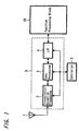
- FIG. 1 is a block diagram showing an example of the
structure of a wireless transmitting portion according to an
embodiment of the present invention;
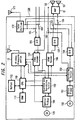
- FIG. 2 is a block diagram showing an example of an audio
recording and reproducing apparatus according to an embodiment
of the present invention;
- FIG. 3 is a block diagram showing an example of a remote
controller according to an embodiment of the present invention;
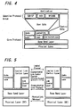
- FIG. 4 is an explanatory diagram showing an example of
protocol stack;
- FIG. 5 is an explanatory diagram showing an example of
the hierarchical structure of wireless communication;
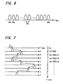
- FIG. 6 is an explanatory diagram showing an example of
the setting of communication frequency;
- FIG. 7 is an explanatory diagram showing a frequency
hopping condition;
- FIG. 8 is an explanatory diagram showing an example of
single-slot packet arrangement according to the time axis;
- FIG. 9 is an explanatory diagram showing an example in
which single-slot packets and multi-slot packets are mixed
according to the time axis;
- FIG. 10 is an explanatory diagram showing an example of
the transmission state between a master and a slave;
- FIG. 11 is an explanatory diagram showing an example of
network structure;
- FIG. 12 is a timing diagram showing an example of
communication with SCO link;
- FIG. 13 is a timing diagram showing an example of
communication based on asynchronous communication method;
- FIG. 14 is a timing diagram showing an example of
communication based on isochronous communication method;
- FIG. 15 is a timing diagram showing an example of
communication based on broadcast communication method;
- FIG. 16 is a timing diagram showing an example of
communication in case where SCO link and ALC link are used
together;
- FIG. 17 is an explanatory diagram showing an example of
the structure of clock data;
- FIG. 18 is an explanatory diagram showing an example of
the structure of address;
- FIG. 19 is a structure diagram showing an example of
generation processing of frequency hopping pattern;
- FIG. 20 is an explanatory diagram showing an example of
packet format;
- FIG. 21 is an explanatory diagram showing an example of
the structure of access code;
- FIG. 22 is an explanatory diagram showing an example of
the structure of a packet header;
- FIG. 23 is an explanatory diagram showing an example of
the structure of payload;
- FIG. 24 is an explanatory diagram showing an example of
the structure of a payload header in a single-slot packet;
- FIG. 25 is an explanatory diagram showing an example of
the structure of a payload header in a multi-slot packet;
- FIG. 26 is an explanatory diagram showing an example of
the structure of the payload of FHS packet;
- FIG. 27 is an explanatory diagram showing an example of
condition transition of devices;
- FIG. 28 is an explanatory diagram showing an example of
communication for inquiry;
- FIG. 29 is a timing diagram showing an example of
inquiry processing;
- FIG. 30 is an explanatory diagram showing an example of
call communication;
- FIG. 31 is a timing diagram showing an example of call
processing;
- FIG. 32 is an explanatory diagram showing an example of
hierarchical structure based on the AV/C protocol;
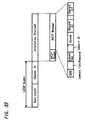
- FIG. 33 is an explanatory diagram showing an example of
packet structure based on the AV/C protocol;
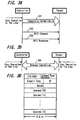
- FIG. 34 is an explanatory diagram showing an example of
the building of connection based on the AV/C protocol and the
transmission of a command and a response;
- FIG. 35 is an explanatory diagram showing an example of
release connection based on the AV/C protocol;
- FIG. 36 is an explanatory diagram showing an example of
data structure based on the AV/C protocol;
- FIG. 37 is an explanatory diagram showing an example of
commands;
- FIG. 38 is an explanatory diagram showing an example of
a command and a response;
- FIG. 39 is an explanatory diagram showing an example of
transmission among devices according to an embodiment of the
present invention;
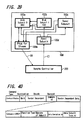
- FIG. 40 is an explanatory diagram showing an example of
command structure according to an embodiment of the present
invention;
- FIG. 41 is an explanatory diagram showing an example of
a control command transmission state;
- FIG. 42 is an explanatory diagram showing an example of
command and response data in the example of FIG. 41;
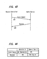
- FIG. 43 is an explanatory diagram showing an example of
a status command transmission state according to an embodiment
of the present invention;
- FIG. 44 is an explanatory diagram showing an example of
command and response data in the example of FIG. 43;
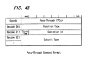
- FIG. 45 is an explanatory diagram showing an example of
the format of a pass-through command; and
- FIG. 46 is an explanatory diagram showing examples of
operation id's of the pass-through command.
-
BEST MODE FOR CARRYING OUT THE INVENTION
-
Hereinafter, an embodiment of the present invention will
be described with reference to FIGS. 1 to 46.
-
According to the present invention, a short-distance
wireless transmission method standardized based on the Bluetooth
norm is applied to a system in which a wireless network is built
among plural devices. Here, the system is constituted mainly
with electronic devices such as video devices and audio devices.
-
FIG. 1 is a block diagram showing an example of the
structure of a wireless transmitting portion according to an
embodiment of the present invention. A transmission/reception
processing portion 2 connected to an antenna 1 executes high-frequency
signal processing so as to carry out radio
transmission processing and radio reception processing. A
signal to be transmitted by the transmission/reception
processing portion 2 is transmitted at a channel set up at an
interval of 1 MHz in 2.4 GHz band. A signal of each channel is
subjected to a processing called frequency hopping for changing
transmission frequency at a slot interval which will be
described later. Assuming that the frequency hopping is carried
out for each slot, because a slot takes 625µseconds, the
frequency is switched 1,600 times per second thereby preventing
an interference with another radio communication. As modulation
method for radio transmission signal, modulation method called
GFSK (Gaussian filtered FSK) is employed. This modulation
method is a frequency shift modulation method in which the band
is limited by a low-pass filter having a frequency transmission
characteristic having Gaussian distribution. A signal received
by the transmission/reception processing portion 2 and a signal
to be transmitted by the transmission/reception processing
portion 2 are subjected to base band processing by a data
processing portion 3. The Bluetooth standard employs TDD (Time
Division Duplex) in which basically transmission and reception
are carried out alternately and the data processing portion 3
carries out a processing of the transmission slot and a
processing of reception slot alternately. A function processing
block 20 is connected to the data processing portion 3 through
an interface portion 4 so that received data is supplied to the
function processing block 20 and data transmitted from the
function processing block 20 is converted to transmission slots
by the data processing portion 3. A processing for transmission
in the transmission/reception processing portion 2, the data
processing portion 3 and the interface portion 4 is carried out
under control of the controller 5. In stead of the controller 5
a central control unit incorporated in, for example, respective
devices can be used. Aside from the central control unit, a
dedicated controller prepared for short distance wireless
communication may be used.
-
The transmission/reception processing portion 2, the data
processing portion 3, the interface portion 4 and the controller
5 correspond to the short distance wireless communication
portion 100 for carrying out the Bluetooth communication.
-
The function processing block 20 connected to the short
distance wireless communication portion 10 serves for a portion
for carrying out actually the function of the apparatus. For
example, in case of a video camera and a video
recording/reproducing apparatus, it corresponds to a portion for
processing for recording and reproduction of video data and
audio data. In case of an audio recording/reproducing
apparatus, it corresponds to a portion for processing for
recording and reproducing audio data. In case of a computer
unit, it corresponds to a portion for carrying out data
processing based on a prepared program. By incorporating or
externally connecting the transmission processing unit having
such a structure in/to various appliances, data transmission
among various appliances is enabled.
-
In addition, the short distance wireless communication
portion 10, other than the case of being incorporated in the
electronic equipment main body, may be constructed by an
apparatus separate from the apparatus main body so as to be
externally connected thereto.
-
FIG. 2 is a diagram showing an example of the configuration
in which the block of the audio recording/reproducing apparatus
100 is employed as the function processing block 20. The audio
recording/reproducing unit 100 of this example comprises a
function block which by using magneto-optic disc or optical disc
incorporated in a resin package called mini disc (MD) as a
recording medium, records/reproduces voice signal or the like as
digital data, a function block in which by using an optical disc
called compact disc (CD) as a recording medium, reproduces voice
signal or the like as digital data and a function block for
receiving radio broadcasting.
-
In the structure of the recording system of the audio
recording/reproducing apparatus 100, analog voice signal of two
channels inputted from outside are converted to digital voice
data by an analog/digital converter 101. The converted digital
voice data is supplied to an ATRAC encoder 102 and encoded to
voice data according to ATRAC (Adaptive Transform Acoustic
Coding) method. If the digital voice data is inputted directly
from outside, that inputted voice data is supplied directly to
the ATRAC encoder 102 not through the analog/digital converter
101. Data encoded by the encoder 102 is supplied to the
recording/reproducing portion 103 and subjected to a processing
for recording. An optical pickup 104 is driven based on the
processed data so as to record data into a disc (magneto-optic
disc) 105. Meanwhile, magnetic field modulation is carried out
by a magnetic head (not shown) at the time of recording.
-
In the meantime, the audio recording/reproducing apparatus
100 of this example has a tuner portion 172, which is capable of
supplying two-channel audio signal of radio broadcasting
received through an antenna 171 to an input stage of the
analog/digital converter 101 through change-over switches 161,
162. Therefore, audio signal received by the tuner portion 172
can be recorded in the disc 105.
-
As for the configuration of the reproducing system of the
disc recording/reproducing portion, data recorded in the disc
(magneto-optic disc or optical disc) 105 is read out by the
optical pickup 104 and subjected to reproduction processing by
the recording/reproducing portion 103 so as to obtain voice data
compressed according to the ATRAC method. This reproduced voice
data is supplied to an ATRAC decoder 106 so as to decode to
digital voice data of a predetermined style and then, the
decoded voice data is supplied to a digital/analog converter
107, converted to two-channel analog voice signal and outputted.
If digital voice data is intended to be outputted directly to
outside, voice data decoded by the ATRAC decoder 106 is
outputted directly not through the digital/analog converter 107.
An example shown in FIG. 2 has such a structure that the
outputted voice signal converted to analog is supplied to an
amplifier unit 51, and subjected to voice output processing such
as amplification so as to output two-channel voice (audio) from
connected speakers 52, 53.
-
As the configuration of another disc reproducing portion
than the recording/reproducing portion described up to here,
data recorded in a disc (optical disc) 152 is read out by an
optical pickup 151 and subjected to reproduction processing by a
reproducing portion 153 so as to obtain digital voice data of
two-channel or the like. This reproduced voice data is supplied
to a digital/analog converter 154, converted to two-channel
analog voice signal and outputted. If it is intended to output
digital voice data directly to outside, it is outputted directly
not through the digital/analog converter 154. In the example of
FIG. 2, as the output system for analog voice signal, reproduced
output from a disc recording/reproducing portion using MD and
reproduced output from a disc reproducing portion using CD are
selectively supplied to an amplifier 51 by means of change-over
switches 163, 164. Further, the output system for digital voice
signal is changed over by the change-over switch 165 in the same
manner.
-
The audio recording/reproducing apparatus 100 of this
embodiment has the radio processing block 10 for carrying out
radio communication according to the aforementioned Bluetooth
method to carry out two-way radio communication with a mating
radio processing block through the connected antenna 1. For
example, voice data received by this radio processing block 10
is supplied to the recording/reproducing portion 102 through the
ATRAC encoder 102 and recorded in the disc 105. Further, voice
data reproduced from the disc 105 is supplied to the radio
processing block 10 from the recording/reproducing portion 102
through the ATRAC decoder 106 so as to enable radio
communication to the mating unit. Further, voice data
reproduced from the disc 152 can be supplied from the
reproducing portion 153 to the radio processing block 10 and
transmitted to a mating appliance by radio. Voice data received
by the tuner 172 can be supplied to the radio processing block
10 and transmitted to the mating appliance by radio.
-
Recording processing, reproduction processing and radio
broadcasting reception processing by the audio
recording/reproducing apparatus 100 and transmission and
reception by the radio processing block 10 are carried out under
a control by the central control unit (CPU) 110. A memory 111,
which is a work RAM, is connected to the CPU 110. Further,
operation information from a control panel 112 is supplied to
the CPU 110 to carry out action control corresponding to the
operation information. If control data such as control command
and response which will be described later is received by the
radio processing block 10, that data is supplied to the CPU 110
so that the CPU 110 can carry out action control and processing
correspondingly. If it is intended to transmit the control data
such as control command and response from this unit 100 by
radio, control data to be transmitted is generated within the
CPU 110 and transmitted from the radio processing block 10 by
radio.
-
FIG. 3 is a diagram showing an example of the structure of a
remote control unit 200 for controlling the audio
recording/reproducing apparatus 100 from a remote place. The
remote control unit 200 transmits radio signal based on the
Bluetooth standard to the audio recording/reproducing apparatus
100 so as to control an operation of the audio
recording/reproducing apparatus 100.
-
In the remote control unit 200, an operation key 201 for
instructing various actions is prepared and an operation of the
operation key 201 is recognized by the central control unit
(CPU) 202, which is a control means. Further, it has a display
panel 203 for displaying an operating condition and an action of
a controlled unit, so that an appropriate display is carried out
with characters, numerals and graphics under control of the CPU
202.
-
A control code generating portion 204 is connected to
the CPU 202, so that for example when the operation key 201 is
operated, a control code corresponding to that controlled action
is generated in the control code generating portion 204 and that
generated control code is transmitted to the radio processing
block 10 by radio. Further, the control code received by the
radio processing block 10 is supplied to a reception code
determining portion 205 and the reception code determined by
this reception code determining portion 205 is supplied to the
CPU 202.
-
The remote control unit 200 of this has a function for
receiving audio data transmitted by radio from the audio
recording/reproducing apparatus 100, so that the received audio
is outputted to the remote control unit 200 from the described
head phone 208. That is, when audio data is received by the
radio processing block 10, that audio data is supplied to the
reproduction processing portion 206 to carry out audio
reproduction processing such as demodulation, analog conversion
and amplification and then the processing audio signal is
supplied to the head phone 208 connected to a head phone
terminal 207 and outputted.
-
Remote control of the audio recording/reproducing
apparatus 100 can be carried out from the remote control unit
200 by transmitting radio signal based on the Bluetooth standard
between the audio recording/reproducing apparatus 100 having
such a structure and the remote control unit 200. Further, an
operating condition of the audio recording/reproducing apparatus
100 can be displayed through the display panel 203 possessed by
the remote control unit 200. Audio reproduced from a disc by
the audio recording/reproducing apparatus 100 can be outputted
through the head phone 208 connected to the remote control unit
200.
-
Next, a processing for executing wireless communication
with other devices based on the bluetooth method using the
short-distance wireless communication portion mounted on each
device will be described later.
-
FIG. 4 is a diagram showing a protocol stack necessary
for carrying out wireless communication based on the bluetooth.
The protocol for the entire system of the bluetooth is divided
to a core protocol, which is a major portion of the protocol of
the bluetooth, application software which executes application
service and an adaptive protocol group for matching
communication protocols between the core protocol and
application.
-
The protocol of the bluetooth core is composed of five
protocols or comprised of a physical layer, a base band layer,
an actual data processing layer and a logical link control
layer, successively provided on top of another from the bottom
layer.
-
The adaptive protocol group adapts the core protocol to
application software so that various kinds of existing
applications can be applied. This adaptive protocol group
includes, for example, TCP/IP protocol, RFCOMM protocol for
emulating serial port, a driver of an device (HID: Human
Interface Device) which user operates and the like. For
transmission of the AV/C data, which will be described later, a
protocol which adapts a profile corresponding to this adaptive
protocol group is prepared. The structure of a protocol
necessary for transmitting the AV/C data will be described
later.
-
As physical layer, frequency hopping type spectrum
diffusion method using a frequency band of 2.4 GHz is employed.
Transmission power is restricted to about 100 mW maxium,
assuming a wireless communication over a short-distance of about
100 m. Further, this physical layer allows transmission power
to be reduced up to - 30 dBm minimum by control from the link
layer.
-
The base band layer is defined as a protocol for
interfacing actual transmission/reception data with the physical
layer. This layer provides with a communication link for
transmitting/receiving data sent from a higher layer. At this
time, control of the frequency hopping and control of the time
axis slot are carried out. Further, processings for resending a
packet, error correction and error detection are controlled by
this base band layer.
-
The link control layer is a protocol for interfacing the
transmission/reception packet on communication link is a
protocol, which specifies setting of communication link to the
base band layer or setting of various communication parameters
relating to that link. Those are defined in the link control
layer as control packet and communicate with a link control
layer of an opposing terminal as required. This layer receives
a direct control from a higher level application as required.
-
In the audio layer, audio data is exchanged after a
communication link allowing the link control layer to transmit
or receive data is set up. The audio data mentioned here refers
to mainly audio data for communication through telephone and
includes a dedicated processing layer at a relatively lower
level layer in order to suppress data transmission delay to a
minimum limit.
-
The logical link control layer is a protocol for
interfacing with the link control layer and the base band layer
so as to control the logical channel. Other transmission data
than audio data which the audio layer handles is provided from a
high level application to ethical link layer and actual data
which is exchanged there is exchanged without making conscious
of the size and timing of the data packet. For the reason, the
logical link control layer controls data of the high level
application as logical channel so as to carry out data division
and data reconstruction.
-
FIG. 5 shows a processing at each layer when wireless
communication is carried out between two devices. A physical
wireless communication line link is set up in the physical layer
and transmission/reception of the packet is carried out through
a link set up in the base band layer. Transmission and
reception of control packet is carried out through a
communication link control channel. Transmission and reception
of user data packet is carried out through logical channel.
This user data corresponds to stream data or command which is
required to be transmitted.
-
Next, physical communication frequency set-up processing
upon wireless communication based on this method will be
described. FIG. 6 is a diagram showing the frequency for use
based on this method and as shown in FIG. 6, there are 79
communication frequencies at an interval of 1 MHz from 2402 MHz
to 2480 MHz. Each packet to be transmitted occupies a single
transmission spectrum in these 79 transmission frequencies.
Then, the transmission spectrum for use changes (hopping) every
625 µseconds.
-
FIG. 7 shows an example of this communication frequency
hopping, in which the communication frequency changes at random
every 625 µseconds from a specific timing t0. If the
communication frequency changes every 625 µseconds, the hopping
occurs about 1600 times for a second, so that it is diffused
within a band shown in FIG. 7 and transmitted, indicating that
the spectrum diffusion is being caused.
-
In case of bluetooth, a unit of the packet is 625
µseconds. This single unit of the packet may be used
continuously to carry out transmission. For example, when bidirectional
transmission is carried out between two devices,
communications of both directions do not use the same quantity
of the packets and in some case, plural packets may be used for
communication in one direction.
-
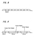
If all packets to be transmitted are packets of 625
µseconds as shown in FIG. 8, frequency hopping occurs every 625
µseconds as shown in FIG. 7. Contrary to this, in case where as
shown in FIG. 9, three packets are used continuously or five
packets are used continuously, transmission frequency is fixed
while that slot continues.
-
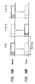
FIG. 10 shows communication status between two devices.
When one device for carrying out wireless communication is
assumed to be master while the other one is assumed to be slave,
data of slot configuration is sent from the master to the slave
in the period of a slot (625 µseconds) (FIG. 10A) and in a next
slot period, data of slot configuration is sent from the slave
to the master (FIG. 10B). Hereinafter, the alternate
transmission is repeated as long as the transmission continues.
The frequency for wireless communication is changed such that
the frequency is f(k), f(k+1), f(k+2), ...at every slot as
described above.
-
FIG. 11 is a diagram showing an example of the network
structure composed of plural devices. In a communication system
standardized according to the bluetooth, its network may be
constructed with not only one-to-one wireless communication, but
also with plural devices.
-
That is, in case where wireless communication is carried
out between two devices, one device serves as the master while
the other device serves as the slave as shown on the left end of
FIG. 11, so that bi-directional wireless communication is
executed between master MA11 and slave SL11 under a control of
the master MA11. As shown in the center of FIG. 11, it is
permissible to prepare three slaves SL21, SL22, SL23 controlled
by, for example, a single master MA 21 so that the network is
constructed so as to carry out wireless communication among
these four devices.
-
Further, as shown on the right end of FIG. 11, it is
permissible to prepare three masters MA31, MA32, MA33 and slaves
SL31, SL32, SL33, SL34, SL35, SL 36 controlled independently by
each master, construct three networks and then connect these
three networks so as to expand the network configuration. In
any case, direct communication cannot be executed between the
slaves but communication is always executed through the master.
-
Meanwhile, a network comprised of a master and a slave
directly communicating with that master is called pico-net. A
network group having plural masters (that is, a network group
comprised of plural pico-nets) is called caster net.
-
Next, the kinds of links for carrying out communication
between devices based on bluetooth will be described. The
bluetooth includes two kinds of the links, SCO (Synchronous
Connection-Oriented) link and ACL (Asynchronous Connection-Less)
link, which can be used separately depending on the purpose of
application.
-
The SCO link is connection type which executes one-to-one
communication between the master and a specific slave and
so-called call switching type link. This link is used for an
application in which real-time performance is required about
mainly audio performance. In this SCO link, a communication
slot is assured preliminarily at a specified interval on
communication link within the pico-net and even if other data
transmission occurs halfway, data transmission by the SCO link
is taken as precedence. That is, as shown in FIG. 13, for
example, SCO communication slot is transmitted alternately at a
specified interval between the master and the slave.
-
This SCO link can support three SCO links maximum
corresponding to a single master at the same time. In this
case, three SCO links may be supported by a slave or a SCO link
may be supported for each of different three slaves. Meanwhile,
the SCO link has no resending function and no error correction
code is attached to a packet to be transmitted through the SCO
link.
-
The ACL link is so-called packet switching type
connection type, which enables 1-to-multiple communication
between the master and plural slaves. Although it is capable of
communicating with any slave in the pico-net, effective
communication speed of each slave may be changed depending on
data quantity or the number of the slaves. The SCO link and the
ACL lank may be used mixedly.
-
The ACL link allows a single master to communicate with
up to seven slaves at the same time. However, the ACL link
which can be set up to each slave within a pico-net is only one
and a slave cannot set up plural ACL links at the same time. To
activate plural applications with a single slave, it is
necessary to protocol-multiplex a higher level application.
Unless specified specially, ACL packet of single slot is used
for communication between the master and the slave. For the
slave to transmit the ACL packet of multi-slot, a permission
from the master is needed. Although the master can reject a
request for transmission of the ACL packet of the multi-slot
from the slave, the slave always must receive a request for
transmission from the master.
-
The master notifies the slave of only a upper limit
value of the multi-slot and whether or not the ACL packet of the
multi-slot should be transmitted depends upon determination of
the slave. On the other hand, because which the ACL packet is
single slot or multi-slot depends on the determination of the
master, the slave needs to always prepare for receiving the
multi-slot packet.
-
The ACL packet is provided with the following three
packet communication methods irrespective of definitions of the
single slot and multi-slot. The first one is asynchronous
communication method (Asynchronous transfer), the second one is
Isochronous communication method (Isochronous transfer) and the
third one is broadcast communication method (Broadcast
transfer).
-
The asynchronous communication method is a communication
method for transmitting/receiving an ordinary packet. Data
transmission speed is changed depending on traffic amount of
slaves existing in the pico-net and packet resending due to
deterioration of communication line quality.
-
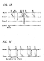
FIG. 13 shows a case where three slaves ( slaves 1, 2, 3)
in the same pico-net communicates according to asynchronous
communication method. The ACL packet is transmitted from the
master to the respective slaves 1, 2, 3 in succession and each
slave receiving the ACL packet resends a packet for confirming
the reception to the master.
-
Meanwhile, stream data such as audio data and video data
may be sometimes transmitted according to the asynchronous
communication method. In case for transmitting stream data
according to the asynchronous communication method, a time stamp
is attached to each ACL packet so as to secure continuity of
stream data on the reception side.
-
According to the Isochronous communication method, a
packet is always transmitted from the master to the slave within
the period of a predetermined time slot. This method allows to
secure a minimum delay of data to be transmitted. In case of
isochronous communication, the slot interval needs to be agreed
as maximum polling time, between the master and the slave before
communication based on isochronous communication method is
started.
-
The master can specify the maximum polling interval to
the slave forcibly and reject a request for setting isochronous
communication method from the slave. However, the slave cannot
specify the maximum polling interval to the master or make a
request for setting isochronous communication.
-
FIG. 14 shows a case for carrying out communication
between the master and the slave according to the isochronous
communication method. As shown in FIG. 14, the ACL packet is
transmitted from the master to a slave and just after receiving
the ACL packet, the slave resends a packet for reception
confirmation to the mater.
-
The broadcast communication method is set up by setting
a slave identifier in the packet header to zero. Consequently,
the broadcast communication packet can be sent from the master
to all the slaves. A slave receiving the same packet does not
transmit a packet for reception confirmation corresponding
thereto. Although the slave does not confirm the reception, the
master transmits broadcast communication packet continuously
several times. The master needs to notify all the slaves of the
frequency of the transmissions of plural times prior to
broadcast communication.
-
FIG. 15 shows an example of communication to all the
slaves in the pico-net according to the broadcast communication
method. A point marked with X in FIG. 15 indicates an example
in which the slave cannot receive a packet and by transmitting
NBC times repeatedly, broadcast communication can be carried out
to all the slaves securely.
-
FIG. 16 is a diagram showing an example of communication
using both the SCO link and ACL link. In this example, the SCO
packet is transmitted through the SCO link between the master
and the
slave 1 at a predetermined cycle. The ACL packet is
transmitted to three
slaves 1, 2, 3 as required. Further, the
broadcast communication packet is also transmitted repeatedly
predetermined times. when a timing for sending the SCO packet
arrives while this broadcast communication packet is being
transmitted repeatedly, the SCO packet is transmitted.
-
Next, the internal clock possessed by the master and the
slave will be described. According to this communication
system, respective devices use an internal clock so as to set up
a frequency hopping pattern and the like. The clock possessed
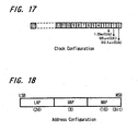
by the master and the slave is set up with a count value of, for
example, a 28-bit counter of 0 to 27 as shown in FIG. 17. A
single clock of this counter is 312.5 µseconds. This 312.5
µseconds is a minimum time unit for call processing and inquiry
processing. In the 28-bit counter in which the value is counted
up by one every 312.5 µseconds, a period is about 23 hours,
thereby raising random characteristic of frequency hopping
pattern.
-
The period of 312.5 µseconds set up with a clock value
of 0 bit is a time period of transmission packet when the mater
carries out call and inquiry. The period of 625 µseconds set up
with a clock value of the first bit is a time period of a slot
whose communication frequency is changed. The period of 1.25 m
seconds set up with a clock value of the second bit is a
transmission/reception time frequency of the master or slave.
The period of 1.28 seconds set up with a clock value of the 12th
bit is a clock timing in a time period for changing the
reception frequency upon inquiry and call.
-
Each slave adds a specified offset value to its own
clock so that it coincides with a clock of the master by
referring to the master clock and then, uses the summed clock
for communication.
-
When calculating a frequency hopping pattern in the
master and slave, a 48-bit address added to each terminal as
well as this clock is used as parameter. The 48-bit address is
an absolute address which is defined according to an address
system based on IEEE802 specification and allocated to each
terminal of the bluetooth independently. FIG. 18 is a diagram
showing the structure of a 48-bit address, in which its lower 24
bits is composed of LAP (Lower Address Part), next 8 bits is
composed of UAP (Upper Address Part) and remaining 16 bits are
composed of NAP (Non-significant Address Part).
-
For generation of the frequency hopping pattern
synchronous in the pico-net, 24 bits of the entire LAP and lower
4 bits of the UAP in the master address, totaling 28 bits are
used. Consequently, a frequency hopping pattern based on the
master address is given to each pico-net. Because the master
address is notified to the slave when communication status is
gained, each slave can calculate the same frequency hopping
pattern as the master independently.
-
FIG. 19 is a diagram showing an example of the structure
for calculating a communication frequency. According to this
structure, the low level 28 bits of the master address and low
level 27 bits of the 28-bit clock are supplied to a
communication frequency selecting portion 8 and a communication
frequency which is a channel frequency hopping pattern is
automatically determined. The call frequency hopping pattern
and the inquiry frequency hopping pattern are different from the
channel frequency hopping pattern.
-
Next, the structure of data to be transmitted between
the master and the slave will be described. FIG. 20 is a
diagram showing a packet format. The packet is composed of
three portions, access code, packet header and payload. The
payload is set to a variable length depending on the amount of
data to be transmitted at that time.
-
FIG. 21 is a diagram showing the structure of access
code. The access code is composed of 68-bit or 72-bit data,
indicating a destination of transmission packet and added to all
packets to be transmitted/received. Depending on the kind of
the packet, only this access code is attached.
-
Its preamble is composed of a fixed 4-bit length in
which a pattern of 1, 0 is repeated depending on the LSB of a
sync word. A trailer is composed of 4 bits in which a pattern
of 1, 0 is repeated depending on the MSB of the sync word. Any
one functions to remove the signal DC components of the entire
access code.
-
The 48-bit synch word is 64-bit data generated with 24-bit
LAP in the 48-bit address. This synch word is used to
identify the pico-net. In case of transmission in which no
master address or clock can be obtained, a different synch word
may be used in a packet for use in inquiry and call.
-
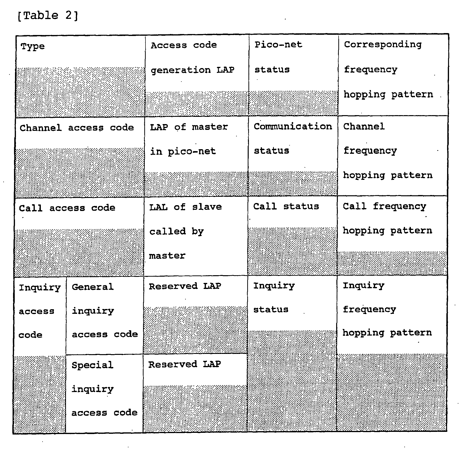
Next Table 2 summarizes access code types.
-
FIG. 22 is a diagram showing the structure of a packet
header. The packet header is a portion including a parameter
necessary for controlling the communication link in the base
band layer.
-
The 3-bit AM ADDR is an identification field for
specifying a slave on communication in the pico-net and a value
to be allocated by the mater to each slave.
-
The 4-bit TYPE is a packet type field for specifying
what packet the entire packet is.
-
The 1-bit FLOW is a field for use in control of flow
control of a packet which communicates through the ACL link.
-
The 1-bit ARQN is a 1-bit field for use in notifying a
packet transmission side of whether or not there is any error in
a received packet. According to the bluetooth norm, any
response packet for reception confirmation is not prepared and a
packet reception confirmation is sent to a packet transmitter
using this ARQN field. Depending on which this field value is 1
or 0, whether or not there is any error in the received packet
or that there is an error is notified to the mating. Whether or
not there is any error in the received packet is determined
according to a header error detection code attached to a packet
header of the received packet and an error detection code
attached to the payload.
-
The 1-bit SENQ is a field for use for controlling so
that the resent packet does not overlap on the reception side.
When resending the same packet, the value is inverted between 1
and 0 alternately each time when a packet is transmitted.
-
The 8-bit HEC is a field in which the packet header
error correction code is disposed. This error correction code
is generated using a generating polynomial of g(D) = D
8 + D
7 + D
5
+ D
2 + D + 1. An initial value set up in an 8-bit shift
register for generating error correction code sets up 8 bits of
the UAP in an address for bluetooth described above. The
address used here coincides with an address used for generating
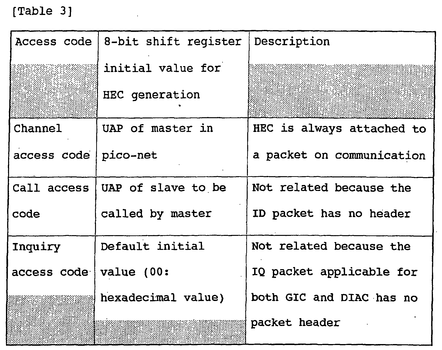
the access code. The following Table 3 summarizes the initial
values upon generating this error correction code.
-
In order to identify a pico-net on communication, a
channel access code (CAC) generated according to 24 bits of the
LAP of the master address is used. In order to attain
synchronism in transmission within the pico-net, it is necessary
to synchronize the frequency hopping pattern with the time slot.
At this time, even if other master having the same LAP exists
nearby and further, the synchronism between the frequency and
the time slot happens to coincide, it is possible to remove this
by using the HEC which is a packet header error correction code.
-
The payload accommodates user data to be transmitted or
received actually between terminals or control data. The user
data includes data to be transmitted or received through the SCO
link and data to be transmitted or received through the packet
switching type ACL link.
-
FIG. 23 is a diagram showing the structure of payload of
the ACL link. The payload is comprised of three components,
payload header, payload body and error detection code and the
length of the entire payload is variable. On the other hand,
because the payload of the SCO link secures a communication slot
cyclically, it does not resend data packet and is composed of
only a payload body, while no payload header or error detection
code is added.
-
The payload header is a portion including a parameter
necessary for controlling data of a higher layer than the base
band layer and is data which is included in only the ACL link.
FIG. 24 shows the structure of payload header of a single slot
packet and FIG. 25 shows the structure of a payload header of a
multi-slot packet.
-
The 2-bit L_CH data included in the payload header is a
field for identifying a logical channel for specifying what is
data of a higher layer than the base band layer. The SCO link
and the ACL link are links in the base band layer and the
control thereof is carried out according to information set up
by the packet header. The L_CH identifies a logical channel
which is defined by a higher level layer than the base band
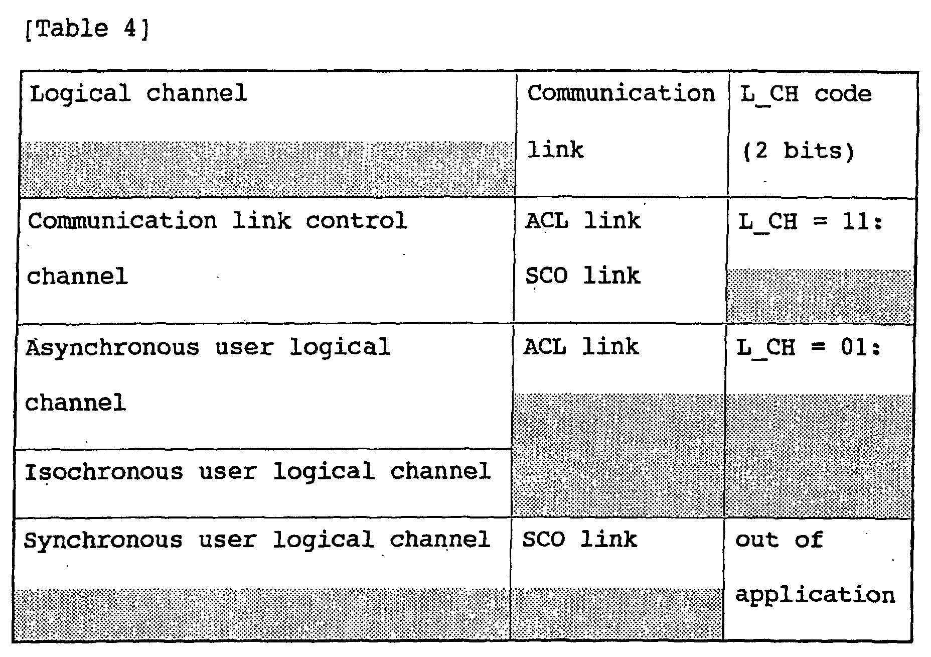
layer and is defined as shown in Table 4 to the three user
logical channels.
-
The 1-bit FLOW is a 1-bit data for use for flow control
of data transmitted or received on user logical channel. The
FLOW is controlled in each user logical channel, so that by
setting FLOW = 0 and returning data, a mating is made to
interrupt transmission of data temporarily. Further, by setting
FLOW = 1 and then returning data when the reception buffer is
empty, the mating is made to restart transmission of data.
Although the setting of this FLOW field is executed by the link
control layer, real-time data flow control is not guaranteed.
The real-time data flow control is all carried out by the base
band layer using the FLOW field in the packet header. Because
data in the control packet is all processed by the link control
layer, it is not transferred to the logical link control layer.
Therefore, the control packet is not affected by the flow
control by this FLOW and its value is always set to 1.
-
5-bit or 9-bit LENGTH is a field indicating the data
length of a payload body in the unit of byte. This is 5-bit
field in case of a single slot packet and 9-bit field in case of
a multi-slot packet.
-
UNDEFINED exists in only the payload header of the
multi-slot packet and is currently an undefined field, which is
always set to 0.
-
Data of a length specified by LENGTH of the payload
header is accommodated in the payload body. Because the payload
of data packet is constructed of only a payload body in SCO link
communication, there is no specification of the data length by
LENGTH. If the DV packet is used, the data length of that data
portion is indicated.
-
The CRC is a 16-bit field indicating an error detection
code and a detection code for detecting whether or not there is
any error in the payload header and payload. This error
detection code is generated using a generating polynomial of
g(D) = D16 + D12 + D5 + 1. An initial value to be set in a 16-bit
shift register upon its generation is set up to a 16-bit
value obtained by adding 8-bit zeroes to 8 bits of the UAP in an
address, which has been already described. The address for use
here is the same as the address for use in generating the access
code like the HEC.
-
Next, the packet type will be described.
-
The TYPE field specifies a packet type as described
about the packet header. If speaking about this packet type to
be set up here, there are a common packet used in the SCO link
and ACL link in common and an inherent packet of the SCO link or
ACL link.
-
First, the common packet will be described. The common
packet includes NULL packet, POLL packet, FHS packet, DM1
packet, IQ packet and ID packet.
-
The NULL packet is a packet comprised of an access code
and a packet header, having no payload. The length of the
packet is fixed to 126 bits. This packet is a packet for
transmitting/receiving the status of a communication link and
controls packet reception confirmation (ARQN) and flow control
(FLOW). A confirmative response of a packet corresponding to
the reception of this NULL packet is not required.
-
The POLL packet is a packet comprised of an access code
and a packet header like the NULL packet and fixed to 126 bits
so as to control the status of communication link. In case of
this POLL packet, when the POLL packet is received, it is
necessary to transmit a response about confirmation of the
packet even if there is no data to be transmitted, different
from the NULL packet.
-
The FHS packet is an important control packet for
achieving synchronism in the pico-net and transmitted when a
clock and an address which are independent parameters for
establishing synchronism between the mater and the slave are
exchanged. FIG. 26 is a diagram showing an example of the
structure of the payload of the FHS packet. The payload of the
FHS packet is comprised of 11 fields and composed of 160 bits by
adding a 16-bit error detection code to 144 bits of this 11
fields. The 11 fields composing the FHS packet will be
described.
-
The 34-bit parity bit is a field including a parity to a
sync word in an access code set up by the FHS packet.
-
The 24-bit LAP is low level 24 bits of an address of a
terminal for transmitting the FHS packet. 2 bits following the
LAP is an undefined field and set to 0.
-
The 2-bit SR is a 2-bit field, which upon call,
specifies the frequency of repetition for the master to transmit
an ID packet string and the period of scanning for the slave to
scan the ID packet string from the master.
-
The 2-bit SP is a field, which upon inquiry, specifies a
time for the slave to execute independent call scanning after
the slave receives an IQ packet from the master and transmit the
FHS packet to the master.
-
The 8-bit UAP is high-level 8 bits of an address of a
terminal for transmitting the FHS packet.
-
The 16-bit NAP is 16 bits except LAP and UAP within an
address of a terminal for transmitting the FHS packet.
-
The class of a 24-bit device is a field indicating the
kind of the terminal.
-
The 3-bit AM ADDR is a 3-bit field for the master to
identify the slave. In the call processing, the master
specifies a slave identifier for use in the pico-net through the
FHS packet which the master transmits to the slave. In the FHS
packet which the slave transmits as a response of IQ packet from
the master, AM ADDR is meaningless and needs to be set to 0.
-
26-bit CLK 27-2 is a field indicating high level 26 bits
in a clock possessed by the terminal. This clock has a clock
accuracy of 1.25 µseconds and when transmitting the FHS packet,
the clock value at that time needs to be set.
-
3-bit page scan mode is a field for specifying a mode of
call scan of default supported by a terminal which transmits the
FHS packet.
-
Next, the DM1 packet will be described. If the DM1
packet is being transmitted or received through the SCO link, it
always functions as a control packet. On the other hand, if it
is transmitted or received through the ACL link, it not only
functions as a control packet but also is used for
transmission/reception of data packet.
-
If it is transmitted as a common packet through the SCO
link or ACL link, it is defined as a control packet of the link
control layer. When the DM1 packet is transmitted or received
through the ACL link, which it is user packet or control packet
cannot be distinguished only if a field (TYPE) for specifying a
packet type is seen. Thus, by setting logical channel type
field of the payload header to L_CH = 11, it is specified that
the DM1 packet is a control packet for the link control layer.
In case of data packet, L_CH = 01 or L_CH = 10 is set up by
fragmentation of original user data.
-
The IQ packet is a packet which the master broadcasts
corresponding to inquiry and composed of only inquiry access
codes.
-
The ID packet is a packet which upon call, the master
transmits by specifying a specific slave and composed of only
call access codes. The IQ packet and ID packet are packets not
defined on the type field of the packet header.
-
Next, SCO packet, which is data packet transmitted or
received on the SCO link, will be described. The SCO packet is
comprised of four kinds, HVI packet, HV2 packet, HV3 packet and
DV packet.
-
The payload of the HV1 packet is composed of only a
payload body, which accommodates user data of 10 bytes.
-
Because basically the SCO packet is not resent, this 10 bytes do
not contain any error detection code. Then, the data is
subjected to error correction coding at 1/3 rate, so that
finally it has a payload length of 240 bits.
The payload of the HV2 packet is composed of only a
payload body and accommodates 20-byte data. This 20 bytes do
not include any error detection code. Then, the data is
subjected to error correction coding at 2/3 rate, so that
finally, it has a payload length of 240 bits.
-
The payload of the HV3 packet is composed of only a
payload body and accommodates 30-byte data. This 30 bytes do
not contain any error detection code. This 30 bytes is not
subjected to error correction coding.
-
The DV packet is comprised of an audio part of a fixed
length of 10 bytes and a variable length data part of up to 9
bytes. Although any error correction code is not contained in
10 bytes of the audio part, a 2-byte error detection code for a
part of 10 bytes max. expanded from 1-byte payload header is
attached to the data part.
-
The ACL packet transmitted/received on the ACL link
includes DM1 packet, DH1 packet, DM3 packet, DH3 packet, DH5
packet, DH5 packet and AUX1 packet.
-
The payload of the DM1 packet is comprised of 1-byte
payload header, a variable length payload body of 17 bytes max.
and an error detection code.
-
The configuration of the DH1 packet is the same as the
DH1. However, the payload is not subjected to error correction
coding. Therefore, it is capable of transmitting or receiving a
variable length data of up to 27 bytes.
-
The payload of the DM3 packet is comprised of a 2-byte
payload header, a variable length payload body of up to 121
bytes and an error correction code. The payload of the DM3
packet is subjected to error correction coding at 2/3 rate.
-
The configuration of the DH3 packet is the same as that
of the DM3 packet. However, the payload is not subjected to
error correction coding. Therefore, it is capable of
transmitting or receiving a variable length data of up to 183
bytes.
-
The payload of the DM5 packet is comprised of 2-byte
payload header, a variable length payload body of up to 224
bytes and a 2-byte error correction code.
-
The configuration of the DH5 packet is the same as that
of the DM5 packet. However, the payload is not subjected to
error correction coding. Therefore, it is capable of
transmitting or receiving a variable length data of up to 339
bytes.
-
The AUX packet is the same as the DH1 packet in case
where no 2-byte error detection code is contained. That is, the
AUX1 packet is not resent. The payload body is increased by 2
bytes, so that it is capable of transmitting or receiving a
variable length data of up to 29 bytes.
-
Next, transition status based on bluetooth will be
described. The transition status of this method is composed of
three phases relating to transmission and low consumption power
mode relating to power consumption at a terminal. The three
phases relating to transmission is divided to waiting phase,
synchronism establishing phase and transmission phase. Further,
the low consumption power mode is divided to three types, park
mode, hold mode and sniff mode. FIG. 27 is a diagram showing a
status transition and there are transitions indicated with
arrows.
-
The waiting phase (S11) is composed of a processing
condition and a phase in which any packet is not transmitted or
received. Just after a terminal is powered on or when
communication link is cut out, the terminal is kept in the
waiting phase. In this waiting phase, the roles of the master
and the slave are not different.
-
The synchronism establishing phase is composed of two
kinds, inquiry (S12) and call (S13).
-
The inquiry is a first stage processing condition for
establishing synchronism in the pico-net. A terminal intending
to transmit for the first time is always transferred to inquiry
after the waiting phase.
-
The call is a second stage processing condition for
establishing synchronism in the pico-net. Although basically,
that condition is attained from the inquiry, if the first stage
processing for establishing synchronism in the pico-net with the
inquiry condition is already completed, the call may be attained
directly from the waiting phase.
-
In this inquiry, the roles of the master and the slave
are clearly different. The master in this processing condition
broadcasts IQ packets continuously irrespective of whether or
not a slave exists nearby. If a slave in the inquiry condition
exists nearby, the slave transmits the FHS packet to the master
in order to notify its attribution each time when it receives
the IQ packet. Through this FHS packet, the master is capable
of knowing an address and a clock of the slave.
-
FIG. 28 is a diagram showing a processing which the
master and slave in this inquiry condition carry out. If as
shown on the left of FIG. 28, the master in the center transmits
the IQ packet, a surrounding slave transmits the FHS packet to
the master as shown on the right of FIG. 28. The master in the
inquiry condition receives the FHS packet from unspecified
plural slaves.
-
Here, a fact that plural slaves transmits the FHS packet
to a specific IQ packet at the same time is a problem. If
plural FHS packets are transmitted at the same time, a collision
of the packets occurs so that the master cannot distinguish the
transmitted FHS packets. According to the bluetooth, the random
time is backed off when transmitting the FHS packet in order to
avoid such a collision. That is, the slave does not transmit
the FHS packet to the master with respect to the IQ packet
received for the first time and after that, interrupts reception
of the IQ packet while the random time is backed off. After
that, the slave restarts reception of the IQ packet and next,
just after the IQ packet is received, transmits the FHS packet
to the master. If the slave receives the FHS packet, it
interrupts the reception of the IQ packet again while the random
time is backed off. After that, this action is repeated.
-
FIG. 29 is a diagram showing an outline of processing in
the master and slave upon the inquiry. Because the master does
not notify the slave that it can receives the FHS packet without
any error, the slave in the inquiry condition remains in a state
just after the FHS packet is transmitted. However, because the
same IQ packet is broadcast repeatedly in a specified interval
of time, the master receives plural FHS packets for each slave
in the inquiry condition. That is, by continuing the inquiry in
a specified interval of time, certainty of transmission/
reception of the FHS packet is intensified.
-
In case of the call, the roles of the master and slave
are different. With this processing condition, the master
selects a slave scheduled to communicate with based on
information of the FHS packet transmitted/received in the
inquiry and transmits the ID packet to that slave. If the
master confirms the reception of the ID packet, it transmits the
FHS packet to that slave. Consequently, the slave can know the
address and clock of the master.
-
As an access code to the ID packet and FHS packet to be
transmitted/received here, the call access code is used.
-
FIG. 30 shows an outline of processing operation carried
out by the master and slave in the call condition. If the
master located in the center transmits the ID packet to the
slave as shown on the left of FIG. 30, the slave notifies of
reception confirmation. Further, if the master transmits the
FHS packet to the slave as shown on the right of FIG. 30, the
slave notifies of reception confirmation.
-
Different from a processing to unspecified plural slaves
upon inquiry, processing is exchanged between a specified slave
and master upon inquiry. Because transmission and reception of
the packet can be carried out one to one, the master and slave
can execute processing while confirming the transmission and
reception.
-
After receiving the ID packet from the master, the slave
transmits the same ID to the master so as to notify of reception
confirmation. Next, the master transmits the FHS packet to the
slave so as to notify the slave of its own address and clock.
If the slave receives this FHS packet without any error, it
transmits the ID packet to the master so as to confirm the
reception. At this time, information about the address and
clock necessary for synchronism in the pico-net is exchanged
between the master and the slave together with the inquiry
processing.
-
FIG. 31 is a diagram showing an example of processing
between the master and the slave upon call.
-
The communication connection phase shown in the status
transition diagram of FIG. 28 includes connection (S14) and data
transfer (S15). Because in this communication connection phase,
the master is synchronous with the slave in the pico-net after
synchronism establishing phase, this allows actual communication
to be executed. In the connection status, transmission/reception
of data packet is not carried out. Those
transmitted/received at this time are restricted to control
packet for setting communication link, control packet relating
to security and control packet relating to low consumption power
mode.
-
On the other hand, in data transfer status,
transmission/reception of data packet is permitted. If the
status is changed to connection for the first time after the
synchronism establishing phase, basically it cannot be changed
to data transmission unless processings for connection
certification and coding between the master and slave are
completed. The roles of the master and slave on connection are
different depending on the content of control package to be
controlled there.
-
Transmission and reception of data packet on data
transfer are carried out according to rules of the master, slave
and time slot. If a terminal relating to data transmission cuts
out communication or a controller in a terminal is reset in
terms of hardware, the terminal is turned from data transmission
state to waiting state.
-
The low consumption power mode refers to a mode for
providing low consumption power status of a terminal which is
turned from connection state. This low consumption power mode
is divided to three types, park mode (S16), hold mode (S17) and
sniff mode (S18).
-
The park mode is a mode particular to the slave and a
low consumption power mode which maintains synchronism in the
pico-net established by connection.
-
The hold mode is a low consumption power mode which both
the master and the slave can turn to and is a mode which
maintains synchronism in the pico-net established by connection
and in case of the slave, holds a slave identifier given by the
master.
-
The sniff mode is a low consumption power mode
particular to the slave and is a mode in which the slave
maintains synchronism in the pico-net established by connection
like in case of the hold mode and holds a slave identifier given
by the master.
-
Under the bluetooth, it is possible to switch between a
master and a specified slave in the pico-net.
-
Processing about security to be carried out with the
communication connection phase being connected is largely
divided to certification and coding. Certification processing
refers to determining whether or not connection between itself
and a specified mating is permitted. Coding processing refers
to protecting data which is being transmitted from being tapped
by a third party.
-
The security of the bluetooth is controlled under a
concept of link key. The link key refers to a parameter for
controlling one-to-one security between specified two terminals.
This link key must not be disclosed to the third party.
-
As this link key, an initialization key for use between
terminal which try to connect each other for the first time is
used. If a link key is set up in the data base as parameter by
connecting previously, that set up link key is used. The
initialization key is generated using a PIN code from a higher
level application and internally generated data.
-
General processing based on the bluetooth norm has been
described up to here. In the short-distance wireless
communication of this example, a command for controlling such an
electronic device as audio device and video device (these
devices are generally called AV devices) and a response are
transmitted.
-
FIG. 32 is a diagram showing configuration of
transmission for transmitting this command and response with a
hierarchical structure. A terminal on command transmission side
is called controller while a terminal which receives that
command and sends back a response to the command transmitter is
called target. The relation between this controller and target
is other concept than the master and slave relation described
above, necessary for carrying out communication connection
control and basically, either may function as a terminal of the
master or slave.
-
A layer for processing L2CAP packet for transmitting
protocol data for control exists on the base band layer and
AVCTP (Audio/Video Control Transport Protocol) protocol is
prepared further thereon. A protocol called AV/C command is
prepared on that protocol in order to control the AV device.
-
FIG. 33 is an example of the data structure of the L2CAP
packet for transmitting data of that protocol. A header is
attached to a heading portion of a payload section of this
packet (portion marked with L2CAP Header), indicating data
length (length) and channel ID. A subsequent section is actual
information (information).
-
AVCTP header and AVCTV message are disposed in the
information section. The AVCTP message data comprises "0000"
data (4 bits) indicating AV/C data, command/response data (4
bits) indicating a command and a response, data (5 bits)
indicating subunit type, data (3 bits) indicating subunit ID,
opcode (opcode) data (8 bits) specifying a function and operands
which are data attached to the functions (operand : 8 bits),
operand [0], operand [1], ....operand [n] (n is an arbitrary
integer) . The data structure of the AVCTP shown in FIG. 34
applies a data structure specified as AV/C command set which is
a standard for transmitting device control data on a network
connected through a cable-based bus line.
-
FIG. 34 is a diagram showing a condition in which a
command and a response are transmitted by wireless between the
controller and the target. If there is any user at the terminal
of the controller side so that the necessity of transmitting a
command to a target device occurs, the controller establishes a
connection with the target (step S31) and transmits the AV/C
command from the controller to the target through the
established connection (step S32). The target receiving this
command transmits a response to that command to the controller
(step S33). Then, a processing corresponding to the command is
executed as required. In case of a command for confirming the
status of the target, a required data is sent back to the
controller as a response.
-
If a processing for removing the connection is executed
by user operation on the controller side or user operation on
the target side as shown in FIG. 35, release connection
processing for removing the connection set up to transmit the
command or response is executed (step S34).
-
Next, the structure of the AV/C command set (that is,
AVCTP data) for use in the system of this example will be
described with reference to FIGS. 36-46. FIG. 36 indicates the
data structure of a section to be transmitted as the AV/C
command (that is, AVCTP data in case of this example) in the
unit of 8 bits. The AV/C command set is a command set to
control an AV device and CTS (command set ID) is "0000". The
AV/C command frame and response frame are exchanged. A response
to a command is sent for example, within a specified period.
However, in some case, a temporary response is sent within the
specified period and then a formal response is sent after some
extent of interval.
-
The CTS indicates an ID of the command set and under the
AV/C command set, CTS = "0000". When the packet is a command,
the field of c type/response (ctype/response) indicates a
function class of the command, and when the packet is response,
it indicates a command processing result. The command is
largely defined in four types, namely, (1) command (CONTROL) for
controlling the function from outside, (2) command (STATUS) for
inquiring about the state from outside, (3) command (GENERAL
INQUIRY (presence or absence of support of opcode)) for
inquiring about presence or absence of support of control
command from outside, (4) command (NOTIFY) for requesting to
notify outside of a change of the state.
-
The response is sent back depending on the kind of the
command. The responses to the control command are NOT
IMPLEMENTED (not implemented), ACCEPTED (accepted), REJECTED
(rejected) and (INTERIM)(interim). The responses to the STATUS
command are NOT IMPLEMENTED, REJECTED, IN TRANSITION (in
transition), and STABLE (stable). The responses to commands
(GENERAL INQUIRY and SPECIFIC INQUIRY) asking from the outside
wheter or not there is any support for a command are IMPLEMENTED
(implemented) and NOT IMPLEMENTED. The responses to a command
demanding that a change of state be known to the outside
(NOTIFY) are NOT IMPLEMENTED, REJECTED, INTERIM and CHANGED
(changed).
-
The subunit type (subunit type) is installed to specify
the function of the unit, for example, tape recorder/player,
tuner and the like are allocated. The subunit is allocated with
BBS (bulletin board subunit), a subunit for publicizing
information to other devices in addition to the function for
corresponding with devices. In order to determine if plural
subunits of the same kind exist, a subunit ID (subunit id) is
employed as a determination number for addressing. Opcode which
is a operation code indicates a command and operand indicates a
parameter of command. There are prepared fields (additional
operands) which are added depencing on necessity. 0 data and the
like are added depending on necessity.
-
FIG. 37 shows a concrete example of the AV/C command.
The left side of FIG. 37 indicates a concrete example of command
type/response. An upper portion in the table indicates commands
and a lower portion indicate responses. CONTROL is allocated to
"0000", STATUS is allocated to "0001", SPECIFIC INQUIRY is
allocated to "0010", NOTIFY is allocated to "0011", and GENERAL
INQUIRY is allocated to "0100". "0101-0111" is reserved for
future specification. NOT INPLEMENTED is allocated to "1000",
ACCEPTED is allocated to "1001", REJECTED is allocated to
"1010", IN TRANSITION is allocated to "1011", IMPLEMENTED/STABLE
is allocated to "1100" and CHNGED is allocated to "1101" and
INTERIM is allocated to "1111". "1110" is reserved for future
specification.
-
The middle of FIG. 37 shows a concrete example of the
subunit type. Video Monitor is allocated to "00000", Disk
recorder/Player is allocated to "00011", Tape recorder/Player is
allocated to "00100", Tuner is allocated to "00101", Video
Camera is allocated to "00111", Subunit to be used as a bulletin
board called BBS (Bulletin Board Subunit) is allocated to "
01010", Subunit type uniqe to a manufacturer (Vendor unique) is
allocated to "11100" and specified Subunit type extended to next
byte is allocated to "11110". Although unit is allocated to
"11111", this is used for case for sending to just a unit, for
example, power ON/OFF.
-
The right side of FIG. 37 shows a concrete example
of opcode. opcode table exists for each subunit type and here,
the subunit type indicates opcode in case where the subunit type
is Tape recorder/Player. Operand is defined for each opcode.
Here, a value unique to a manufacturer (VENDOR-DEPENDENT) is
allocated to "00h", SEACH MODE is allocated to "50h", TIMECODE
is allocated to "51h", ATN is allocated to "52h", MEMORY OPEN is
allocated to "60h", READ MEMORY is allocated to "61h", WRITE
MEMORY is allocated to "62h", LOAD is allocated to "C1h", RECORD
is allocated to "C2h", PLAY is allocated to "C3h" and WIND is
allocated to "C4h".
-
FIG. 38 shows a concrete example of the AV/C command and
response. For example, if a reproduction instruction is
dispatched to a reproducing appliance which serves for a target
(consumer), the controller sends a command shown in FIG. 38(A)
to the target. Because this command uses the AV/C command set,
it comes that CTS = "0000". Because ctype uses a command
(CONTROL) for controlling the unit from outside, it comes that
ctype = "0000" (see FIG. 37). Because the subunit type is Tape
recorder/Player, it comes that subunit type = "00100" (see FIG.
37). Because id indicates case of ID0, it comes that id = 000.
opcode is "C3h" meaning reproduction (see FIG. 37). operand is
"75h" meaning FORWARD. Then, if reproduction is carried out,
the target sends back a response shown in FIG. 38B to the
controller. Because accepted meaning reception enters into
response, response = "1001" (see FIG. 38). Because others are
the same as FIG. 38A excluding response, a description thereof
is omitted.
-
By transmitting such specified AVDCP protocol data
with the configuration shown in FIG. 33 according to Bluetooth
method by radio, control of a mating unit and the like are
enabled.
-
In this example, a case where a panel subunit is
provided as a unit controlled with the AVDCP protocol data will
be described. As described above, in the unit controlled
according to the AVDCP protocol, each function portion is called
subunit. As one of the subunits, there is a panel subunit.
This panel subunit displays a panel for GUI (graphic user
interface) about actions which can be carried out on the
controlled unit by means of the control unit such as a remote
control unit and if a key operation corresponding to a display
on that panel occurs, the function displayed on the panel
instructed by the key is executed. If the control is carried
out using this panel unit, that control is executed using, for
example, pass-through command. This pass-through command will
be described later.
-
An example of the audio recording/reproducing apparatus
100 shown in FIG. 2 will be described with reference to FIG. 39.
As subunits, this audio recording/reproducing apparatus 100
comprises a disc subunit 100a which is a recording/reproducing
portion for MD (mini disc) which executes recording and
reproduction of audio data into/from a disc, a CD (compact disc)
reproducing portion 100b for executing reproduction of audio
data from the disc, a tuner subunit 100c for receiving radio
broadcasting and a panel subunit 100d for executing operations
of the respective subunits 100a, 100b, 100c. The disc subunits
100a, 100b are provided with ID0, ID1 as subunit ID so that they
can be identified. The panel subunit 100d is so constructed
employing the CPU 110 shown in FIG. 2 and part of peripheral
memory.
-
In the meantime, the CPU 110 is used as control means
for the subunits 100a, 100b, 100c.
-
With such a structure, the remote control unit 200
sends control command C1 to the panel subunit 100d so as to
remote control the audio appliance 100. When outputting stream
data (audio data or the like) to outside from the respective
subunits 100a, 100b, 100c by radio, it is transmitted directly
from a stream plug 100e as data D1.
-
FIG. 45 is a diagram showing the configuration of pass
through (PASSTHROUGH) command to be transmitted to the panel
subunit. The section of opcode is provided with a code (7C16)
indicating pass through command. Function type data is disposed
in the section of operand[0]. In the section of operand[1],
state bit is disposed at a head bit and operation ID is disposed
in remaining 7 bits. When this state flag is posted (when a
data exists), it is indicated that it is a command indicating a
function block to be controlled and 7-bit operation ID is
neglected. When no state flag is posted (when 0 data exists),
it is indicated that the operation ID is valid for the remaining
7 bits. Subunit type data is disposed in a section following
the operand[2]. In the meantime, numerals expressed by
attaching (16) are hexadecimal numbers (indicated by 0, 1, ...
9, A, B, ... F) indicated with 4-bit data.
-
As an operation ID disposed in the section of
operand[1], various operations are allocated to respective code
values as shown in FIG. 46, for example. For example, codes for
instructing directions of up and down on the GUI screen and
selection thereof, codes for instructing for selection of a menu
screen, and codes for directly instructing an operation of audio
appliance or video appliance such as reproduction, stop,
recording, rapid feed, rewind are allocated.
-
In this example, by transmitting the remote control unit
200 a specified command to the audio appliance 100, it is
possible to preliminarily carry out instruction to the subunit
provided in this audio appliance 100.
-
FIG. 40 shows an example of the configuration of command
to be sent from the remote control unit 200 for this purpose.
Upper data shown in FIG. 40 is disposed in each of the data
sections shown in FIG. 33. Its command type is [CONTROL] for
controlling the state or [STATUS] for inquiry thereof. A
destination of this command is for all sections of an
appropriate unit and therefore, this command is sent to the
unit. In the section of opcode, vendor dependent value
indicating that it is a code particular to manufacturer is
provided. In the section of operand[0], a company ID for
identifying a manufacturer is disposed. In a section following
operand [1], data for investigating which command is capable of
making control is disposed.
-
As for data in the section following operand[1], as
shown at the lower step of FIG. 40, it is indicated that the
first category code is AVDCP protocol code and next, data about
function type to be inquired is disposed. Here, data for
specifying the subunit is disposed. Next, the operation ID is
disposed. Finally, data such as the subunit ID is disposed.
-
FIG. 41 shows a processing for registering a subunit
for which a command to be transmitted to a mating appliance is
to be executed as [CONTROL] for controlling the state as a
command type of this command. First of all, the remote control
unit 200 sends a subunit specification command to the audio
appliance 100. At this time, as the subunit type, data for
specifying disc subunit of the ID0 is attached (step S11). At
this time, a state flag (see FIG. 45) is posted. The audio
appliance 100 sends back a response to this command to the
remote control unit 200 (step S12). Then, a subunit specified
at this time is stored (registered) in a panel subunit within
the audio appliance 100.
-
FIG. 42 is a diagram showing an example of data
structure about operation IDs of the command and response at
this time and subunit ID. Under the control command, the
operation ID is invalid and its maximum value is FF. Then, as a
subunit ID, ID for specifying disc subunit 0 is attached. As a
response, operation ID and subunit ID are sent back as they are.
-
When a command for instructing reproduction is sent from
the remote control unit 200 with pass through command (step
S13), the panel subunit sends reproduction command to a disc
subunit (disc subunit of ID0) specified by a command of step S11
so as to start reproduction in an appropriate disc subunit and
send back a response to that command (step S14).
-
Further, when a command for instructing stop of
reproduction from the remote control unit 200 with pass through
command is sent (step S15), the panel subunit sends stop command
to a disc subunit (disc subunit of ID0) specified by a command
of step S11 so as to stop reproduction in an appropriate disc
subunit and send back a response to that command (step S16).
-
If a subunit for control is specified once, it is not
necessary to instruct a subunit each time for commands to be
transmitted after that. Meanwhile, a column in which the
subunit in data is to be specified only has to be a maximum
value (FF) which is invalid data. The specification of this
subunit may be released by sending data for releasing the
specification of the subunit or updated if another subunit
specification exists.
-
Additionally, the registration condition of the subunit
of that appliance can be inquired by sending a command from the
remote control unit to the audio appliance as not the control
command, but as an inquiry [STATUS] command. FIG. 43 shows an
example of this case, in which the remote control unit 200 sends
a command of [STATUS] to the audio appliance 100 in order to
verify the specification condition of the subunit (step S21).
At this time, the status flag (see FIG. 45) is set to 1. With a
response to this command, data about the subunit ID registered
to be controlled by the audio appliance 100 is attached (step
S22).
-
FIG. 44 is a diagram showing an example of data
configuration about operation ID of a command and response at
this time and subunit ID. Under the status command, a code
about the function to be inquired with the operation ID is
attached. Because in this example, a subunit which executes an
instruction for reproduction is inquired, a code (44)
corresponding to reproduction is attached. Then, the subunit ID
is set to a maximum value (FF).
-
In a response to this command, the operation ID is kept
as it is and the registered subunit ID is attached to the
subunit ID so that reproducing action is carried out when an
instruction for reproduction is given. In this example, the
subunit ID is sent back with the ID of disc subunit 0.
-
In case where a subunit is registered such that it can
be controlled without specifying the subunit, the registration
condition can be recognized simply by sending a response in this
way.
-
In the embodiments described up to here, a case of
transmitting by radio according to the so-called Bluetooth
standard has been described. In case for transmitting control
data or the like through another radio transmission network
also, of course, the processing by the present invention may be
applied.
-
Although an example of the audio appliance has been
described about the subunit provided on the appliance, the
present invention may be applied to another appliance such as a
video appliance.
-
Further, the present invention may be applied to a
transmission network in which respective appliances are
connected in series through wire bus line. For example, the
present invention may be applied to bus line called IEEE (The
Institute of Electrical and Electronics Engineers) 1394 type.
In this case, the above described respective commands are
executed in asynchronous transmission and if transmission of
stream data with that command is instructed, they can be
executed in isochronous transmission.
-
As explained above, according to the present invention,
by specifying a function block which is an object for control by
transmission of a first command, it is not necessary to specify
any function block which is the object for control when
transmitting a second command after that. Thus, the command
configuration can be simplified, so that it is possible to
control one appliance from the other appliance favorably with
such a simple structure.
-
In this case, because the first command is instructed by
posting a predetermined flag, a function block which is an
object for control can be specified.
-
Further, because radio transmission network is employed
as transmission network and the command is transmitted through a
first channel secured within that radio transmission network,
the object for control can be specified easily by radio
transmission.
-
Further, because the transmission network is a network
in which appliances are connected through a predetermined bus
line and the command is executed in asynchronous communication
on the bus line, the object for control can be specified easily
by data transmission through the bus line.
-
According to the present invention, the function block
which is the object for control on the side of controlled
appliances can be recognized easily from another appliance, the
function block which is the object for control can be specified
and recognized easily so as to carry out control.
INDUSTRIAL APPLICABILITY .
-
As described so far, according to the data transmission
method, the data transmission system and the data transmitting
apparatus of the present invention, if a wireless transmission
network for carrying out wireless transmission among, for
example, audio devices or video devices is constructed and the
other device is remotely controlled from a specified device in
this network, a control target functional block is designated by
the transmission of the first command to make it unnecessary to
designate the control target functional block when a later
command is transmitted, thereby making it possible to simplify
structure and to control the other device from one device with
simple structure. In addition, it is possible to easily check
the control target function block of the to-be-controlled device
from the other device and to easily conduct checking if the
control target functional block is specified in advance and
controlled.