EP1197923A2 - Annotation management - Google Patents
Annotation management Download PDFInfo
- Publication number
- EP1197923A2 EP1197923A2 EP01402579A EP01402579A EP1197923A2 EP 1197923 A2 EP1197923 A2 EP 1197923A2 EP 01402579 A EP01402579 A EP 01402579A EP 01402579 A EP01402579 A EP 01402579A EP 1197923 A2 EP1197923 A2 EP 1197923A2
- Authority
- EP
- European Patent Office
- Prior art keywords
- annotation
- displaying
- user
- plane
- computer
- Prior art date
- Legal status (The legal status is an assumption and is not a legal conclusion. Google has not performed a legal analysis and makes no representation as to the accuracy of the status listed.)
- Granted
Links
Images




Classifications
-
- G—PHYSICS
- G06—COMPUTING OR CALCULATING; COUNTING
- G06T—IMAGE DATA PROCESSING OR GENERATION, IN GENERAL
- G06T19/00—Manipulating three-dimensional [3D] models or images for computer graphics
-
- G—PHYSICS
- G06—COMPUTING OR CALCULATING; COUNTING
- G06T—IMAGE DATA PROCESSING OR GENERATION, IN GENERAL
- G06T2219/00—Indexing scheme for manipulating 3D models or images for computer graphics
- G06T2219/004—Annotating, labelling
-
- G—PHYSICS
- G06—COMPUTING OR CALCULATING; COUNTING
- G06T—IMAGE DATA PROCESSING OR GENERATION, IN GENERAL
- G06T2219/00—Indexing scheme for manipulating 3D models or images for computer graphics
- G06T2219/012—Dimensioning, tolerancing
Definitions
- the present invention relates to the field of computer-aided design (CAD), computer aided manufacturing (CAM), computer aided engineering (CAE), and product data management (PDM) systems.
- CAD computer-aided design
- CAM computer aided manufacturing
- CAE computer aided engineering
- PDM product data management
- each annotation which is usually comprised of a piece of text or label and an arrow linking the text or label to the elements of the model to which the annotation applies, is located in a plane, known as the "annotation plane".
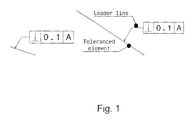
- the text of an annotation can be a flagnote, e.g., a link to an HTML file, or a tolerance specification, which can be a geometrical tolerance specification (e.g., an indication of position, orientation, form or run-out) or a dimensioning tolerance specification (e.g., 4 ⁇ 0.1).
- ⁇ symbol means a perpendicularity tolerance
- 0.1 represents the tolerance value
- A (known as the "datum element") references the model element (e.g., a surface) with respect to which the perpendicularity is defined.
- the leader line which terminates with an arrow, designates the element to which the tolerance applies.
- the present invention provides a system, method, and apparatus for providing increased productivity in positioning 2D representations on 3D models.
- this is accomplished by providing the user with a visual display of the intersection of the surface that is the subject of the annotation, and the plane in which the 2D annotation resides. This is in most cases not a single point but a continuum of points in a straight line or curve on the subject surface. This set of points is called a "trace.”
- the user is provided with a tool for moving the leader line linking the annotation to the surface/geometry.
- the trace of the surface is displayed, indicating to the user all the possible locations to which the leader line can be moved, so that the user may select any point along the trace.
- the system monitors the specific context of the annotation, to determine whether or not the trace that has been calculated is valid in terms of the rules pertaining to the annotation. In the event that the context of the annotation would limit the trace, the trace is so limited.
- the system when the user creates an annotation, the system, based on the type of annotation, the particulars or rules of the annotation, and the geometry selected as the subject of the annotation, proposes one or more annotation planes for proper placement of the annotation so as to comply with the annotation standard. Similarly, when the user seeks to move the annotation plane of an existing annotation, the system will determine whether the new plane selected by the user is appropriate, and if not, will propose an appropriate annotation plane(s).
- the computer 100 has a central processor 101 connected to a processor host bus 102 over which it provides data, address and control signals.
- the processors 101 may be any conventional general-purpose single-chip or multi-chip microprocessor such as a Pentium® series processor, a K6 processor, a MIPS® processor, a Power PC® processor or an ALPHA® processor.
- the processor 101 may be any conventional special purpose microprocessor such as a digital signal processor or a graphics processor.
- the microprocessor 101 can have conventional address, data, and control lines coupling it to a processor host bus 102.
- the computer 100 can include a system controller 103 having an integrated RAM memory controller 104.
- the system controller 103 can be connected to the host bus 102 and provide an interface to random access memory 105.
- the system controller 103 can also provide host bus to peripheral bus bridging functions.
- the controller 103 can thereby permit signals on the processor host bus 102 to be compatibly exchanged with signals on a primary peripheral bus 110.
- the peripheral bus 110 may be, for example, a Peripheral Component Interconnect (PCI) bus, an Industry Standard Architecture (ISA) bus, or a Micro-Channel bus.
- PCI Peripheral Component Interconnect
- ISA Industry Standard Architecture
- Micro-Channel bus Micro-Channel bus
- the controller 103 can thereby allow, for example, a processor 101 having a 64-bit 66 MHz interface and a 533 Mbytes/second data transfer rate to interface to a PCI bus 110 having a data path differing in data path bit width, clock speed, or data transfer rate.
- Accessory devices including, for example, a hard disk drive control interface 111 coupled to a hard disk drive 113, a video display controller 112 coupled to a video display 115, and a keyboard and mouse controller 121 can be coupled to a bus 120 and controlled by the processor 101.
- the computer system can include a connection to a computer system network, an intranet or an internet. Data and information may be sent and received over such a connection.
- the computer 100 can also include nonvolatile ROM memory 122 to store basic computer software routines.
- ROM 122 may include alterable memory, such as EEPROM (Electronically Erasable Programmable Read Only Memory), to store configuration data.
- BIOS routines 123 can be included in ROM 122 and provide basic computer initialization, systems testing, and input/output (I/O) services.
- the BIOS 123 can also include routines that allow an operating system to be "booted" from the disk 113. Examples of high-level operating systems are, the Microsoft Windows 98TM, Windows NTTM, UNIX. LINUX, the Apple MacOS TM operating system, or other operating system.
- An operating system may be fully loaded in the RAM memory 105 or may include portions in RAM memory 105, disk drive storage 113, or storage at a network location.
- the operating system can provide functionality to execute software applications, software systems and tools of software systems.
- Software functionality can access the video display controller 112 and other resources of the computer system 100 to provide models of objects on the video computer display 115.
- a useful purpose of the invention is to identify to the user the set of locations (the locus) that are permissible for the end of the arrow of an annotation, taking into account the meaning of the annotation.
- the system stores a set of data relating to the annotation.
- the system stores the annotation plane, i.e., the plane in which the annotation is located, and the specific geometry referenced by the annotation, as selected by the user and analyzed by the system.
- the type of annotation is stored. This information is used by the system to more precisely understand the selection of a specific geometry by the user, as the selection made by the user may be ambiguous.
- the apparent selection of a cylinder may mean, in the user's mind, either the skin of the cylinder or its axis.
- the system can determine that the user is focusing not on the axis of the cylinder, but on the condition of its skin.
- the system also stores any further indication provided by the user in response to a prompt by the system, e.g., by the opening of a panel of options. This may happen when the previous listed data is not enough to remove all ambiguities.
- the system In addition to storing these annotation-related sets of data, the system also stores the standards themselves. That is, for each type of annotation, the system stores the information that is required in all circumstances, namely the elements that must be selected, the type of the annotation, and the indications that are further required. For each standard-defined annotation, the syntax, or spelling, imposed by the standard, i.e., the contents of the three boxes in the Fig. 1 example, and the corresponding semantics, or grammar, i.e., the meaning of these contents, are analyzed and stored in the system. An example list of standards and proposed standards is set forth below.
- the system retrieves the corresponding data, determines the intersection of the specific geometry selected by the user for the annotation with the plane of the annotation, creates the representation of the intersection and identifies to the user (e.g., by a particular form or color of highlighting) the portions of the intersection, called the trace, that are allowed by the standards for locating the end of the annotation arrow.
- the trace is created by positioning the cursor over a leader line, and clicking and holding a button on a mouse. The user then moves the leader line by moving the cursor, until the arrow is positioned on the trace in a location preferred by the user. The user then releases the button on the mouse, and the trace disappears. This is shown by way of example in Figs. 3-6.
- FIG. 3 an object is shown with an annotation specifying the tolerance for the axis (centerline) of the bore in the object.
- FIG. 3 shows the method of the preferred embodiment for selecting the subject annotation, i.e., by positioning a cursor (a hand in the figure) over the annotation and clicking a mouse, or by selecting the annotation from a specification tree.
- the annotation is called "GDT.1”
- the annotation may be selected by positioning a cursor on the GDT.1 reference of the tree and clicking a mouse.
- Fig. 4 is a snapshot of the screen of the preferred embodiment as it would appear after the annotation in the example has been selected.
- the geometry that is the subject of the annotation is highlighted with parallel black stripes.
- Other methods for highlighting the geometry such as changing its color or highlighting the geometry, could be employed as well.
- Fig. 5 depicts the screen of the preferred embodiment as it would appear after the user has selected the leader line.
- the user selects the leader line by positioning the cursor on the leader line and clicking and holding the mouse.
- the system displays the trace, indicating acceptable locations for placement of the arrow of the leader line. This is shown in Fig. 5 by the dotted black line 50.
- the trace 50 is the intersection of the toleranced geometry and the annotation plane.
- Fig. 6 shows the leader line in place in a new location on the trace.
- the trace of acceptable locations for the leader line may not be the entire intersection of the geometry with the annotation plane.
- the trace may be limited by the context of the annotation and the rules of the standard for the annotation.
- An example of this type of situation is shown in Figs. 7 and 8.
- the object that is the subject of the design is a cylinder 65.
- a straightness specification 60 which is a geometric tolerancing specification, lies in the annotation plane 61, depicted by a dashed line.
- a dimensioning specification i.e., " ⁇ 25 ⁇ 1" which applies to the location of the axis of the cylinder. According to the rules of the specifications, when the two specifications are not aligned, for example as shown in Fig.
- the straightness specification applies to the surface of the cylinder. However, if the two specifications are aligned, as shown in Fig. 8, the straightness specification applies not to the surface of the cylinder, but to the axis of the cylinder. Therefore, depending on the relative positioning of the specifications, the meaning changes. This is dictated by the specification standards, which are stored in the system.
- the system will display a trace that is composed of the intersection of the annotation plane and the geometry (the cylinder), minus that portion of the intersection that would align the two specifications. This is shown in Fig. 7 by lines 63, which have a gap at the location of the dimensioning specification. The user is thus informed not to move the leader line to the gap, but only to the displayed trace 63. In the preferred embodiment, the user is prevented from moving the leader line to the gap.
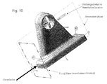
- FIG. 9 an object is shown, together with a tolerancing specification relating to the axis of the bore in the object.
- the annotation 70 lies in the annotation plane 71.
- a fixed plane 72 is also shown, for the purposes of illustration.
- the system determines the new location for the annotation, such that the relative position of the object and the annotation remain unchanged. This is shown in Fig. 10.
- the system when the user creates an annotation, the system, based on the type of annotation, the particulars or rules of the annotation, and the geometry selected as the subject of the annotation, proposes one or more annotation planes for proper placement of the annotation so as to comply with the annotation standard.
- the straightness annotation 60 in order to be interpreted properly as applying to the axis of the cylinder, must be in the same plane as the dimensioning specification " ⁇ 25 ⁇ 1", as well as being aligned with it.
- the system will inform the user that the annotation cannot be placed in the plane selected by the user.
- the system will display annotation plane 61, and suggest to the user that the annotation be place therein.
- the system will determine whether the new plane selected by the user is appropriate, and if not, will propose an appropriate annotation plane(s).
- the system may also identify to the user, for example by a different sort of highlighting, the three constituents involved in a tolerancing specification: the text, the arrow and, if applicable, the datum i.e. the toleranced element of the model.
- the foregoing method can be applied to any system for designing objects, including any CAD/CAM/CAE/PDM system.
- the invention may be implemented in digital electronic circuitry, or in computer hardware, firmware, software, or in combinations of them.
- Apparatus of the invention may be implemented in a computer program product tangibly embodied in a machine-readable storage device for execution by a programmable processor; and method steps of the invention may be performed by a programmable processor executing a program of instructions to perform functions of the invention by operating on input data and generating output.
- the invention may advantageously be implemented in one or more computer programs that are executable on a programmable system including at least one programmable processor coupled to receive data and instructions from, and to transmit data and instructions to, a data storage system, at least one input device, and at least one output device.
- the application program may be implemented in a high-level procedural or object-oriented programming language, or in assembly or machine language if desired; and in any case, the language may be a compiled or interpreted language.
- a processor will receive instructions and data from a read-only memory and/or a random access memory.
- Storage devices suitable for tangibly embodying computer program instructions and data include all forms of nonvolatile memory, including by way of example semiconductor memory devices, such as EPROM. EEPROM. and flash memory devices; magnetic disks such as internal hard disks and removable disks; magneto-optical disks; and CD-ROM disks. Any of the foregoing may be supplemented by, or incorporated in, specially designed ASICs (application-specific integrated circuits).
- ASICs application-specific integrated circuits
Landscapes
- Engineering & Computer Science (AREA)
- Computer Graphics (AREA)
- Computer Hardware Design (AREA)
- General Engineering & Computer Science (AREA)
- Software Systems (AREA)
- Physics & Mathematics (AREA)
- General Physics & Mathematics (AREA)
- Theoretical Computer Science (AREA)
- Processing Or Creating Images (AREA)
- Management Or Editing Of Information On Record Carriers (AREA)
- User Interface Of Digital Computer (AREA)
Abstract
Description
- ASME Y14.5M-1994
- "Dimensioning and Tolerancing", revision of ANSI Y14.5M-1982, The American Society of Mechanical Engineers, New York, 1994.
- ASME Y14.5.1M
- "Mathematical Definition of Dimensioning and Tolerancing Principles", revision of ANSI Y14.5M-1982, The American Society of Mechanical Engineers, New York, 1994.
- ASME Y14.8M
- "Castings and Forgings", The American Society of Mechanical Engineers, New York, 1989.
- ASME yl4.24
- "Types and Applications of Engineering Drawings", The American Society of Mechanical Engineers, New York, 1989.
- ASME Y14.34M
- "Associated Lists", The American Society of Mechanical Engineers, New York, 1989.
- ASME Y14.35M
- "Revision of Engineering Drawings and Associated Documents", The American Society of Mechanical Engineers, New York, 1992.
- ASME Y14.36M
- "Surface Texture Symbols", revision of ANSI Y14.36M-1978, The American Society of Mechanical Engineers, New York, 1993.
- ASME Y14.38
- "Abbreviations and Acronyms", The American Society of Mechanical Engineers, New York.
- ASME Y14.100M
- "Engineering Drawing Practices", The American Society of Mechanical Engineers, New York.
- ASME Y14.41
- "Product Definition for Digital Data Files", on work standard, The American Society of Mechanical Engineers, New York.
- ISO 129:1985
- "Technical drawings - Dimensioning - General principles, definitions, methods of execution and special indications", ISO, 1985.
- ISO 286-1:1988
- "ISO system of limits and fits - Part 1: Bases of tolerances, deviations and fits". ISO, 1988.
- ISO 286-2:1988
- "ISO system of limits and fits - Part 2: Tables of standard tolerance grades and limit deviations for holes and shafts", ISO, 1988.
- ISO 406:1987
- "Technical drawings - Tolerancing of linear and angular dimensions", ISO, 1987.
- ISO 1101-2000
- "Geometrical Product Specifications (GPS) - Geometrical tolerancing-Tolerances of form, orientation, location and run-out", revision of ISO 1101-1983, ISO, 2000.
- ISO 1119:1998
- "Geometrical Product Specifications (GPS) - Series of conical tapers and taper angles", ISO, 1998.
- ISO 1302:2000
- "Technical drawings - Method of indicating surface texture", ISO, 2000.
- ISO 1660:1987
- "Technical drawings - Dimensioning and tolerancing of profiles", ISO, 1987.
- ISO 2538:1998
- "Geometrical Product Specifications (GPS) - Series of angles and slopes on prisms", ISO, 1998.
- ISO 2692:1988
- "Technical drawings - Geometrical tolerancing - Maximum material principle", ISO, 1988.
- ISO 2692:1988/ Amd 1:1992
- "Least material requirement", ISO, 1992.
- ISO 2768-1:1989
- "General tolerances - Part 1: Tolerances for linear and angular dimensions without individual tolerance indications", ISO, 1989.
- ISO 2768-2:1989
- "General tolerances - Part 2: Geometrical tolerances for features without individual tolerance indications", ISO, 1989.
- ISO 3040:1990
- "Technical drawings - Dimensioning and tolerancing - Cones", ISO, 1990.
- ISO 5458:1998
- "Geometrical Product Specifications (GPS) - Geometrical tolerancing-Positional tolerancing", ISO, 1998.
- ISO 5459:1981
- "Technical drawings - Geometrical tolerancing - Datums and datum-systems for geometrical tolerances", ISO, 1981.
- ISO/DIS 5459-2:1998
- "Geometrical Product Specifications (GPS) - Datums for geometrical tolerancing - Part 2: Datums and datum-system; explanations and indication", Draft International Standard, ISO, 1998.
- ISO 8015:1985
- "Technical drawings - Fundamental tolerancing principle", ISO, 1985.
- ISO 8785:1998
- "Geometrical Product Specification (GPS) - Surface imperfections-Terms, definitions and parameters", ISO, 1998.
- ISO 10578:1992
- "Technical drawings - Tolerancing of orientation and location-Projected tolerance zone", ISO, 1992.
- ISO 10579:1993
- "Technical drawings - Dimensioning and tolerancing - Non-rigid parts", ISO, 1993.
- ISO 13715:2000
- "Technical drawings - Edges of undefined shape - Vocabulary and indications", ISO, 2000.
Claims (29)
- A computer system operation method for use with a system for displaying representations of objects, the method comprising:displaying a representation of an object;displaying an annotation for the object, said annotation including a leader line connecting the annotation to the object;receiving input from a user specifying movement of said leader line;calculating a trace of possible placement points for attachment of the leader line to the object; anddisplaying said trace.
- The computer system operation method of claim 1, wherein the method further comprises:receiving input from a user specifying a new location for the leader line; anddisplaying the leader line in said new location.
- The computer system operation method of claim 1, wherein the method by which the user specifies movement of the leader comprises:placing a cursor over the leader line, clicking a mouse, and moving the cursor to a new location.
- The computer system operation method of claim 1, wherein said calculation comprises:retrieving stored data containing standards-based rules pertaining to the type of said annotation; anddetermining from said data whether the trace should be modified based on said data, and if so, modifying said trace based on said data.
- A computer system operation method for use with a system for displaying representations of objects, the method comprising:displaying a representation of an object;displaying an annotation for the object;receiving input from a user specifying movement of said object to a new location;displaying said object in said new location;calculating a new location for said annotation such that the spatial relationship between the object and the annotation remains the same as before movement of the object; anddisplaying said annotation in said new location.
- A computer system operation method for use with a system for displaying representations of objects, the method comprising:displaying a representation of an object;receiving input from a user specifying the placement of an annotation in a given plane with respect to said object;determining the type of said annotation, and retrieving annotation placement rules information stored in said system pertaining to said type of annotation; anddetermining from said retrieved information whether the plane chosen by the user for said annotation is consistent with said retrieved information.
- The computer system operation method of claim 6, the method further comprising:notifying the user that the chosen plane is not consistent with said retrieved information in the event that the system determines that the plane chosen by the user for said annotation is not consistent with said retrieved information.
- The computer system operation method of claim 6, the method further comprising:calculating at least one annotation plane for said annotation consistent with said retrieved information, in the event that the system determines that the plane chosen by the user for said annotation is not consistent with said retrieved information; anddisplaying said at least one annotation plane.
- A CAD/CAM apparatus comprising:wherein the central processing unit runs an application program comprising code for causing the apparatus to:an input device;a central processing unit; anda display device;display a representation of an object;display an annotation for the object, said annotation including a leader line connecting the annotation to the object;receive input from a user specifying movement of said leader;calculate a trace of possible placement points for attachment of the leader line to the object; anddisplay said trace.
- The CAD/CAM apparatus of Claim 9, wherein the application program further comprises code for causing the apparatus to:receive input from a user specifying a new location for the leader line; anddisplay the leader line in said new location.
- The CAD/CAM apparatus of Claim 9, wherein the application program further comprises code allowing the user to specify movement of the leader line by a method comprising:placing a cursor over the leader line, clicking a mouse, and moving the cursor to a new location.
- The CAD/CAM apparatus of Claim 9, the application program further comprising code for causing the apparatus to:retrieve stored data containing standards-based rules pertaining to the type of said annotation; anddetermine from said data whether the trace should be modified based on said data, and if so, modify said trace based on said data.
- A CAD/CAM apparatus comprising:wherein the central processing unit runs an application program comprising code for causing the apparatus to:an input device;a central processing unit; anda display device;display a representation of an object;display an annotation for the object;receive input from a user specifying movement of said object to a new location; display said object in said new location;calculate a new location for said annotation such that the spatial relationship between the object and the annotation remains the same as before movement of the object; anddisplay said annotation in said new location.
- A CAD/CAM apparatus comprising;wherein the central processing unit runs an application program comprising code for causing the apparatus to:an input device;a central processing unit; anda display device;display a representation of an object;receive input from a user specifying the placement of an annotation in a given plane with respect to said object;determine the type of said annotation, and retrieve annotation placement rules information stored in said system pertaining to said type of annotation; anddetermine from said retrieved information whether the plane chosen by the user for said annotation is consistent with said retrieved information.
- The CAD/CAM apparatus of claim 14, the application program further comprising code for causing the apparatus to:notify the user that the chosen plane is not consistent with said retrieved information, in the event that the system determines that the plane chosen by the user for said annotation is not consistent with said retrieved information.
- The CAD/CAM apparatus of claim 14, the application program comprising code for causing the apparatus to:calculate at least one annotation plane for said annotation consistent with said retrieved information, in the event that the system determines that the plane chosen by the user for said annotation is not consistent with said retrieved information; anddisplay said at least one annotation plane.
- A computer data signal embodied in a digital data stream comprising data representing the physical configuration of an object, data representing an annotation and a leader line, and data representing a trace, wherein said data stream is generated by a system operating according to a method comprising:displaying a representation of said object;displaying said annotation for said object, said annotation including a leader line connecting the annotation to the object;receiving input from a user specifying movement of said leader line;calculating a trace of possible placement points for attachment of the leader line to the object; anddisplaying said trace.
- The computer data signal embodied in a digital data stream of claim 17, wherein said calculation comprises:retrieving stored data containing standards-based rules pertaining to the type of said annotation; anddetermining from said data whether the trace should be modified based on said data, and if so, modifying said trace based on said data.
- A computer data signal embodied in a digital data stream comprising data representing the physical configuration of an object, and data representing an annotation and a leader line, wherein said data stream is generated by a system operating according to a method comprising:displaying a representation of an object;displaying an annotation for the object;receiving input from a user specifying movement of said object to a new location; displaying said object in said new location;calculating a new location for said annotation such that the spatial relationship between the object and the annotation remains the same as before movement of the object; anddisplaying said annotation in said new location.
- A computer data signal embodied in a digital data stream comprising data representing the physical configuration of an object, and data representing an annotation and a leader line. wherein said data stream is generated by a system operating according to a method comprising:displaying a representation of an object;receiving input from a user specifying the placement of an annotation in a given plane with respect to said object;determining the type of said annotation, and retrieving annotation placement rules information stored in said system pertaining to said type of annotation; anddetermining from said retrieved information whether the plane chosen by the user for said annotation is consistent with said retrieved information.
- The computer data signal embodied in a digital data stream of claim 20, wherein the method further comprises:notifying the user that the chosen plane is not consistent with said retrieved information, in the event that the system determines that the plane chosen by the user for said annotation is not consistent with said retrieved information.
- The computer data signal embodied in a digital data stream of claim 20, wherein the method further comprises:calculating at least one annotation plane for said annotation consistent with said retrieved information, in the event that the system determines that the plane chosen by the user for said annotation is not consistent with said retrieved information; anddisplaying said at least one annotation plane.
- Computer executable code stored on a computer readable medium, the code comprising means for causing a computer to take steps comprising:displaying a representation of an object;displaying an annotation for the object, said annotation including a leader line connecting the annotation to the object;receiving input from a user specifying movement of said leader line;calculating a trace of possible placement points for attachment of the leader line to the object; anddisplaying said trace.
- Computer executable code stored on a computer readable medium according to claim 23, said code further comprising means for causing a computer to take steps comprising:receiving input from a user specifying a new location for the leader line; anddisplaying the leader line in said new location.
- Computer executable code stored on a computer readable medium according to claim 23, said code further comprising means for causing a computer to take steps comprising:retrieving stored data containing standards-based rules pertaining to the type of said annotation; anddetermining from said data whether the trace should be modified based on said data, and if so, modifying said trace based on said data.
- Computer executable code stored on a computer readable medium, the code comprising means for causing a computer to take steps comprising:displaying a representation of an object;displaying an annotation for the object;receiving input from a user specifying movement of said object to a new location;displaying said object in said new location;calculating a new location for said annotation such that the spatial relationship between the object and the annotation remains the same as before movement of the object; anddisplaying said annotation in said new location.
- Computer executable code stored on a computer readable medium, the code comprising means for causing a computer to take steps comprising:displaying a representation of an object;receiving input from a user specifying the placement of an annotation in a given plane with respect to said object;determining the type of said annotation, and retrieving annotation placement rules information stored in said system pertaining to said type of annotation; anddetermining from said retrieved information whether the plane chosen by the user for said annotation is consistent with said retrieved information.
- Computer executable code stored on a computer readable medium according to claim 27, said code further comprising means for causing a computer to take steps comprising:notifying the user that the chosen plane is not consistent with said retrieved information, in the event that the system determines that the plane chosen by the user for said annotation is not consistent with said retrieved information.
- Computer executable code stored on a computer readable medium according to claim 27, said code further comprising means for causing a computer to take steps comprising:calculating at least one annotation plane for said annotation consistent with said retrieved information, in the event that the system determines that the plane chosen by the user for said annotation is not consistent with said retrieved information; anddisplaying said at least one annotation plane.
Applications Claiming Priority (2)
| Application Number | Priority Date | Filing Date | Title |
|---|---|---|---|
| US687533 | 1984-12-28 | ||
| US09/687,533 US6904392B1 (en) | 2000-10-13 | 2000-10-13 | Annotation management |
Publications (3)
| Publication Number | Publication Date |
|---|---|
| EP1197923A2 true EP1197923A2 (en) | 2002-04-17 |
| EP1197923A3 EP1197923A3 (en) | 2003-12-10 |
| EP1197923B1 EP1197923B1 (en) | 2006-01-04 |
Family
ID=24760785
Family Applications (1)
| Application Number | Title | Priority Date | Filing Date |
|---|---|---|---|
| EP01402579A Expired - Lifetime EP1197923B1 (en) | 2000-10-13 | 2001-10-05 | Annotation management |
Country Status (6)
| Country | Link |
|---|---|
| US (1) | US6904392B1 (en) |
| EP (1) | EP1197923B1 (en) |
| JP (1) | JP3679044B2 (en) |
| AT (1) | ATE315258T1 (en) |
| CA (1) | CA2358172C (en) |
| DE (1) | DE60116462T2 (en) |
Cited By (3)
| Publication number | Priority date | Publication date | Assignee | Title |
|---|---|---|---|---|
| EP1450279A3 (en) * | 2003-02-11 | 2005-11-23 | Siemens Aktiengesellschaft | Method for configuring an electrical system |
| WO2009091559A1 (en) * | 2008-01-15 | 2009-07-23 | Google Inc. | Three-dimensional annotations for street view data |
| US11580266B2 (en) | 2018-09-21 | 2023-02-14 | Bricsys Nv | Insertion of annotation labels in a CAD drawing |
Families Citing this family (25)
| Publication number | Priority date | Publication date | Assignee | Title |
|---|---|---|---|---|
| US8432414B2 (en) | 1997-09-05 | 2013-04-30 | Ecole Polytechnique Federale De Lausanne | Automated annotation of a view |
| JP2003296383A (en) * | 2002-04-05 | 2003-10-17 | Denso Corp | 3D modeling system |
| DE10253152A1 (en) | 2002-11-14 | 2004-06-03 | Rudolf Gmbh & Co. Kg Chemische Fabrik | Partially quaternized, amino-functional organopolysiloxanes and their use in aqueous systems |
| JP2006072572A (en) * | 2004-08-31 | 2006-03-16 | Ricoh Co Ltd | Image display method, image display program, and image display apparatus |
| US8245150B2 (en) * | 2004-11-22 | 2012-08-14 | Caterpillar Inc. | Parts catalog system |
| JP2006277167A (en) * | 2005-03-29 | 2006-10-12 | Fuji Xerox Co Ltd | Annotation data processing program, system and method |
| US7734631B2 (en) * | 2005-04-25 | 2010-06-08 | Microsoft Corporation | Associating information with an electronic document |
| DE102005035929A1 (en) * | 2005-07-28 | 2007-02-01 | Siemens Ag | Method for displaying a plurality of images and an image system for carrying out the method |
| US7644363B2 (en) * | 2006-04-10 | 2010-01-05 | Autodesk, Inc. | “For-each” label components in CAD drawings |
| JP5114877B2 (en) * | 2006-06-27 | 2013-01-09 | 富士通株式会社 | Design data creation method, design data creation device, and design data creation program |
| US8817028B2 (en) * | 2009-02-06 | 2014-08-26 | Dassault Systemes Solidworks Corporation | Creating dynamic sets to automatically arrange dimension annotations |
| US9195739B2 (en) | 2009-02-20 | 2015-11-24 | Microsoft Technology Licensing, Llc | Identifying a discussion topic based on user interest information |
| US8749588B2 (en) * | 2009-09-15 | 2014-06-10 | HNTB Holdings, Ltd. | Positioning labels in an engineering drawing |
| US8443280B2 (en) * | 2009-12-15 | 2013-05-14 | Bluebeam Software, Inc. | Method for sequenced document annotations |
| US20110145692A1 (en) * | 2009-12-16 | 2011-06-16 | Peter Noyes | Method for Tracking Annotations with Associated Actions |
| US8823744B2 (en) * | 2012-03-23 | 2014-09-02 | Bluebeam Software, Inc. | Method for indicating annotations associated with a particular display view of a three-dimensional model independent of any display view |
| JP5894506B2 (en) * | 2012-06-08 | 2016-03-30 | 株式会社Pfu | Image processing apparatus, image reading apparatus, image processing method, and image processing program |
| US20140046923A1 (en) | 2012-08-10 | 2014-02-13 | Microsoft Corporation | Generating queries based upon data points in a spreadsheet application |
| JP6080249B2 (en) * | 2012-09-13 | 2017-02-15 | 富士フイルム株式会社 | Three-dimensional image display apparatus and method, and program |
| US10127331B2 (en) * | 2014-12-15 | 2018-11-13 | The Boeing Company | 3D models utilizing 3D markers to indicate engineering requirements |
| WO2016149554A2 (en) * | 2015-03-17 | 2016-09-22 | Environmental Systems Research Institute (ESRI) | Interactive dimensioning of parametric models |
| EP3335170B1 (en) | 2015-08-13 | 2020-10-14 | Bluebeam, Inc. | Method for archiving a collaboration session with a multimedia data stream and view parameters |
| US20180268614A1 (en) * | 2017-03-16 | 2018-09-20 | General Electric Company | Systems and methods for aligning pmi object on a model |
| US11847381B2 (en) | 2018-05-21 | 2023-12-19 | Dassault Systemes Solidworks Corporation | Three-dimensional graphical annotations with semantic attributes |
| CN116824107B (en) * | 2023-07-13 | 2024-03-19 | 北京万物镜像数据服务有限公司 | Processing method, device and equipment for three-dimensional model review information |
Family Cites Families (6)
| Publication number | Priority date | Publication date | Assignee | Title |
|---|---|---|---|---|
| JP3332476B2 (en) * | 1993-06-21 | 2002-10-07 | キヤノン株式会社 | Graphic correction method and information processing apparatus for implementing the method |
| JP2521035B2 (en) * | 1993-12-03 | 1996-07-31 | インターナショナル・ビジネス・マシーンズ・コーポレイション | Placing annotations on the display |
| JP3333319B2 (en) | 1994-06-03 | 2002-10-15 | 三菱電機株式会社 | 2D and 3D integrated CAD system |
| US5526478A (en) | 1994-06-30 | 1996-06-11 | Silicon Graphics, Inc. | Three dimensional model with three dimensional pointers and multimedia functions linked to the pointers |
| US5572639A (en) * | 1995-05-08 | 1996-11-05 | Gantt; Brian D. | Method and apparatus for interactively manipulating and displaying presumptive relationships between graphic objects |
| US6611725B1 (en) * | 2000-02-03 | 2003-08-26 | Solidworks Corporation | Computer drawing system |
-
2000
- 2000-10-13 US US09/687,533 patent/US6904392B1/en not_active Expired - Lifetime
-
2001
- 2001-10-03 CA CA002358172A patent/CA2358172C/en not_active Expired - Lifetime
- 2001-10-05 AT AT01402579T patent/ATE315258T1/en not_active IP Right Cessation
- 2001-10-05 EP EP01402579A patent/EP1197923B1/en not_active Expired - Lifetime
- 2001-10-05 DE DE60116462T patent/DE60116462T2/en not_active Expired - Lifetime
- 2001-10-15 JP JP2001316774A patent/JP3679044B2/en not_active Expired - Lifetime
Cited By (8)
| Publication number | Priority date | Publication date | Assignee | Title |
|---|---|---|---|---|
| EP1450279A3 (en) * | 2003-02-11 | 2005-11-23 | Siemens Aktiengesellschaft | Method for configuring an electrical system |
| US7613593B2 (en) | 2003-02-11 | 2009-11-03 | Siemens Aktiengesellschaft | Methods for configuring an electrical system |
| WO2009091559A1 (en) * | 2008-01-15 | 2009-07-23 | Google Inc. | Three-dimensional annotations for street view data |
| US8072448B2 (en) | 2008-01-15 | 2011-12-06 | Google Inc. | Three-dimensional annotations for street view data |
| US8717354B2 (en) | 2008-01-15 | 2014-05-06 | Google Inc. | Three-dimensional annotations for street view data |
| US9471597B2 (en) | 2008-01-15 | 2016-10-18 | Google Inc. | Three-dimensional annotations for street view data |
| US10540794B2 (en) | 2008-01-15 | 2020-01-21 | Google Llc | Three-dimensional annotations for street view data |
| US11580266B2 (en) | 2018-09-21 | 2023-02-14 | Bricsys Nv | Insertion of annotation labels in a CAD drawing |
Also Published As
| Publication number | Publication date |
|---|---|
| JP2002157285A (en) | 2002-05-31 |
| EP1197923B1 (en) | 2006-01-04 |
| EP1197923A3 (en) | 2003-12-10 |
| CA2358172A1 (en) | 2002-04-13 |
| JP3679044B2 (en) | 2005-08-03 |
| ATE315258T1 (en) | 2006-02-15 |
| US6904392B1 (en) | 2005-06-07 |
| DE60116462T2 (en) | 2006-09-14 |
| DE60116462D1 (en) | 2006-03-30 |
| CA2358172C (en) | 2009-12-15 |
Similar Documents
| Publication | Publication Date | Title |
|---|---|---|
| US6904392B1 (en) | Annotation management | |
| EP1162575B1 (en) | Tool for three-dimensional analysis of a drawing | |
| US6256595B1 (en) | Apparatus and method for manually selecting, displaying, and repositioning dimensions of a part model | |
| USRE36602E (en) | Concurrent engineering design tool and method | |
| EP1035464B1 (en) | selection navigator | |
| EP1059618B1 (en) | 3D-graphics manipulator | |
| US6480813B1 (en) | Method and apparatus for defining a precision drawing in a drawing program | |
| US6256596B1 (en) | Extensible framework for capturing feature information in a neutral format | |
| EP1071014B1 (en) | Adding code in an application during runtime to enrich object behavior | |
| US8126682B2 (en) | Support system with improved reusability of work history data and design support method | |
| US20080183438A1 (en) | Method and system for analyzing three-dimensional linkages | |
| JPH03225523A (en) | Operation visualization device for software component | |
| JP2003044544A (en) | Mold machining support device and mold machining support program | |
| Mohole et al. | WebCAD: a computer aided design tool constrained with explicit ‘design for manufacturability’rules for computer numerical control milling | |
| US7908585B2 (en) | Computer readable recording medium recorded with graphics editing program, and graphics editing apparatus | |
| JP2710380B2 (en) | Device for checking interference between parts | |
| EP1091324B1 (en) | Improved trim operation based on enhanced face definition | |
| JP4946936B2 (en) | Three-dimensional model joint setting method and joint setting program | |
| Conover et al. | Development of a prototype for transfer of drawing annotations into the ASME Y14. 41 standard | |
| EP1816607A2 (en) | Graphics processing apparatus, method and program for constrained manipulation of 3D objects | |
| Yan et al. | Utilizing Large Language Models (LLMs) to Generate AR Content for AR-Assisted Assembly | |
| CN119810314A (en) | An intelligent plan drawing method based on external data processing platform | |
| Lindig | A concept analysis framework | |
| Kramer et al. | The Design Protocol, Part Design Editor, and Geometry Library of the Vertical Workstation | |
| Joardar et al. | CAD data extraction for simulation: an application in camera view modelling |
Legal Events
| Date | Code | Title | Description |
|---|---|---|---|
| PUAI | Public reference made under article 153(3) epc to a published international application that has entered the european phase |
Free format text: ORIGINAL CODE: 0009012 |
|
| AK | Designated contracting states |
Kind code of ref document: A2 Designated state(s): AT BE CH CY DE DK ES FI FR GB GR IE IT LI LU MC NL PT SE TR |
|
| AX | Request for extension of the european patent |
Free format text: AL;LT;LV;MK;RO;SI |
|
| PUAL | Search report despatched |
Free format text: ORIGINAL CODE: 0009013 |
|
| AK | Designated contracting states |
Kind code of ref document: A3 Designated state(s): AT BE CH CY DE DK ES FI FR GB GR IE IT LI LU MC NL PT SE TR |
|
| AX | Request for extension of the european patent |
Extension state: AL LT LV MK RO SI |
|
| 17P | Request for examination filed |
Effective date: 20040301 |
|
| 17Q | First examination report despatched |
Effective date: 20040420 |
|
| AKX | Designation fees paid |
Designated state(s): AT BE CH CY DE DK ES FI FR GB GR IE IT LI LU MC NL PT SE TR |
|
| GRAP | Despatch of communication of intention to grant a patent |
Free format text: ORIGINAL CODE: EPIDOSNIGR1 |
|
| GRAS | Grant fee paid |
Free format text: ORIGINAL CODE: EPIDOSNIGR3 |
|
| GRAA | (expected) grant |
Free format text: ORIGINAL CODE: 0009210 |
|
| AK | Designated contracting states |
Kind code of ref document: B1 Designated state(s): AT BE CH CY DE DK ES FI FR GB GR IE IT LI LU MC NL PT SE TR |
|
| PG25 | Lapsed in a contracting state [announced via postgrant information from national office to epo] |
Ref country code: BE Free format text: LAPSE BECAUSE OF FAILURE TO SUBMIT A TRANSLATION OF THE DESCRIPTION OR TO PAY THE FEE WITHIN THE PRESCRIBED TIME-LIMIT Effective date: 20060104 Ref country code: AT Free format text: LAPSE BECAUSE OF FAILURE TO SUBMIT A TRANSLATION OF THE DESCRIPTION OR TO PAY THE FEE WITHIN THE PRESCRIBED TIME-LIMIT Effective date: 20060104 Ref country code: FI Free format text: LAPSE BECAUSE OF FAILURE TO SUBMIT A TRANSLATION OF THE DESCRIPTION OR TO PAY THE FEE WITHIN THE PRESCRIBED TIME-LIMIT Effective date: 20060104 Ref country code: NL Free format text: LAPSE BECAUSE OF FAILURE TO SUBMIT A TRANSLATION OF THE DESCRIPTION OR TO PAY THE FEE WITHIN THE PRESCRIBED TIME-LIMIT Effective date: 20060104 Ref country code: LI Free format text: LAPSE BECAUSE OF FAILURE TO SUBMIT A TRANSLATION OF THE DESCRIPTION OR TO PAY THE FEE WITHIN THE PRESCRIBED TIME-LIMIT Effective date: 20060104 Ref country code: CH Free format text: LAPSE BECAUSE OF FAILURE TO SUBMIT A TRANSLATION OF THE DESCRIPTION OR TO PAY THE FEE WITHIN THE PRESCRIBED TIME-LIMIT Effective date: 20060104 Ref country code: IT Free format text: LAPSE BECAUSE OF FAILURE TO SUBMIT A TRANSLATION OF THE DESCRIPTION OR TO PAY THE FEE WITHIN THE PRESCRIBED TIME-LIMIT;WARNING: LAPSES OF ITALIAN PATENTS WITH EFFECTIVE DATE BEFORE 2007 MAY HAVE OCCURRED AT ANY TIME BEFORE 2007. THE CORRECT EFFECTIVE DATE MAY BE DIFFERENT FROM THE ONE RECORDED. Effective date: 20060104 |
|
| REG | Reference to a national code |
Ref country code: GB Ref legal event code: FG4D |
|
| REG | Reference to a national code |
Ref country code: CH Ref legal event code: EP |
|
| REG | Reference to a national code |
Ref country code: IE Ref legal event code: FG4D |
|
| REF | Corresponds to: |
Ref document number: 60116462 Country of ref document: DE Date of ref document: 20060330 Kind code of ref document: P |
|
| PG25 | Lapsed in a contracting state [announced via postgrant information from national office to epo] |
Ref country code: DK Free format text: LAPSE BECAUSE OF FAILURE TO SUBMIT A TRANSLATION OF THE DESCRIPTION OR TO PAY THE FEE WITHIN THE PRESCRIBED TIME-LIMIT Effective date: 20060404 |
|
| PG25 | Lapsed in a contracting state [announced via postgrant information from national office to epo] |
Ref country code: ES Free format text: LAPSE BECAUSE OF FAILURE TO SUBMIT A TRANSLATION OF THE DESCRIPTION OR TO PAY THE FEE WITHIN THE PRESCRIBED TIME-LIMIT Effective date: 20060415 |
|
| REG | Reference to a national code |
Ref country code: SE Ref legal event code: TRGR |
|
| PG25 | Lapsed in a contracting state [announced via postgrant information from national office to epo] |
Ref country code: PT Free format text: LAPSE BECAUSE OF FAILURE TO SUBMIT A TRANSLATION OF THE DESCRIPTION OR TO PAY THE FEE WITHIN THE PRESCRIBED TIME-LIMIT Effective date: 20060605 |
|
| NLV1 | Nl: lapsed or annulled due to failure to fulfill the requirements of art. 29p and 29m of the patents act | ||
| REG | Reference to a national code |
Ref country code: CH Ref legal event code: PL |
|
| ET | Fr: translation filed | ||
| PG25 | Lapsed in a contracting state [announced via postgrant information from national office to epo] |
Ref country code: IE Free format text: LAPSE BECAUSE OF NON-PAYMENT OF DUE FEES Effective date: 20061005 |
|
| PG25 | Lapsed in a contracting state [announced via postgrant information from national office to epo] |
Ref country code: MC Free format text: LAPSE BECAUSE OF NON-PAYMENT OF DUE FEES Effective date: 20061031 |
|
| PLBE | No opposition filed within time limit |
Free format text: ORIGINAL CODE: 0009261 |
|
| STAA | Information on the status of an ep patent application or granted ep patent |
Free format text: STATUS: NO OPPOSITION FILED WITHIN TIME LIMIT |
|
| 26N | No opposition filed |
Effective date: 20061005 |
|
| PG25 | Lapsed in a contracting state [announced via postgrant information from national office to epo] |
Ref country code: GR Free format text: LAPSE BECAUSE OF FAILURE TO SUBMIT A TRANSLATION OF THE DESCRIPTION OR TO PAY THE FEE WITHIN THE PRESCRIBED TIME-LIMIT Effective date: 20060405 |
|
| PG25 | Lapsed in a contracting state [announced via postgrant information from national office to epo] |
Ref country code: TR Free format text: LAPSE BECAUSE OF FAILURE TO SUBMIT A TRANSLATION OF THE DESCRIPTION OR TO PAY THE FEE WITHIN THE PRESCRIBED TIME-LIMIT Effective date: 20060104 Ref country code: LU Free format text: LAPSE BECAUSE OF NON-PAYMENT OF DUE FEES Effective date: 20061005 |
|
| PG25 | Lapsed in a contracting state [announced via postgrant information from national office to epo] |
Ref country code: CY Free format text: LAPSE BECAUSE OF FAILURE TO SUBMIT A TRANSLATION OF THE DESCRIPTION OR TO PAY THE FEE WITHIN THE PRESCRIBED TIME-LIMIT Effective date: 20060104 |
|
| REG | Reference to a national code |
Ref country code: FR Ref legal event code: PLFP Year of fee payment: 15 |
|
| REG | Reference to a national code |
Ref country code: FR Ref legal event code: PLFP Year of fee payment: 16 |
|
| REG | Reference to a national code |
Ref country code: FR Ref legal event code: PLFP Year of fee payment: 17 |
|
| REG | Reference to a national code |
Ref country code: FR Ref legal event code: PLFP Year of fee payment: 18 |
|
| PGFP | Annual fee paid to national office [announced via postgrant information from national office to epo] |
Ref country code: SE Payment date: 20201028 Year of fee payment: 20 Ref country code: DE Payment date: 20201022 Year of fee payment: 20 Ref country code: FR Payment date: 20201021 Year of fee payment: 20 Ref country code: IT Payment date: 20201026 Year of fee payment: 20 Ref country code: GB Payment date: 20201022 Year of fee payment: 20 |
|
| REG | Reference to a national code |
Ref country code: DE Ref legal event code: R071 Ref document number: 60116462 Country of ref document: DE |
|
| REG | Reference to a national code |
Ref country code: GB Ref legal event code: PE20 Expiry date: 20211004 |
|
| REG | Reference to a national code |
Ref country code: SE Ref legal event code: EUG |
|
| PG25 | Lapsed in a contracting state [announced via postgrant information from national office to epo] |
Ref country code: GB Free format text: LAPSE BECAUSE OF EXPIRATION OF PROTECTION Effective date: 20211004 |
|
| P01 | Opt-out of the competence of the unified patent court (upc) registered |
Effective date: 20230527 |