EP1197921A2 - Apparatus, system, and method for draping annotations on to a geometric surface - Google Patents
Apparatus, system, and method for draping annotations on to a geometric surface Download PDFInfo
- Publication number
- EP1197921A2 EP1197921A2 EP01308538A EP01308538A EP1197921A2 EP 1197921 A2 EP1197921 A2 EP 1197921A2 EP 01308538 A EP01308538 A EP 01308538A EP 01308538 A EP01308538 A EP 01308538A EP 1197921 A2 EP1197921 A2 EP 1197921A2
- Authority
- EP
- European Patent Office
- Prior art keywords
- annotation
- model
- vertices
- projected
- plane
- Prior art date
- Legal status (The legal status is an assumption and is not a legal conclusion. Google has not performed a legal analysis and makes no representation as to the accuracy of the status listed.)
- Ceased
Links
Images




Classifications
-
- G—PHYSICS
- G06—COMPUTING OR CALCULATING; COUNTING
- G06T—IMAGE DATA PROCESSING OR GENERATION, IN GENERAL
- G06T17/00—Three-dimensional [3D] modelling for computer graphics
- G06T17/20—Finite element generation, e.g. wire-frame surface description, tesselation
-
- G—PHYSICS
- G06—COMPUTING OR CALCULATING; COUNTING
- G06T—IMAGE DATA PROCESSING OR GENERATION, IN GENERAL
- G06T19/00—Manipulating three-dimensional [3D] models or images for computer graphics
-
- G—PHYSICS
- G06—COMPUTING OR CALCULATING; COUNTING
- G06T—IMAGE DATA PROCESSING OR GENERATION, IN GENERAL
- G06T2210/00—Indexing scheme for image generation or computer graphics
- G06T2210/21—Collision detection, intersection
-
- G—PHYSICS
- G06—COMPUTING OR CALCULATING; COUNTING
- G06T—IMAGE DATA PROCESSING OR GENERATION, IN GENERAL
- G06T2219/00—Indexing scheme for manipulating 3D models or images for computer graphics
- G06T2219/004—Annotating, labelling
-
- G—PHYSICS
- G06—COMPUTING OR CALCULATING; COUNTING
- G06T—IMAGE DATA PROCESSING OR GENERATION, IN GENERAL
- G06T2219/00—Indexing scheme for manipulating 3D models or images for computer graphics
- G06T2219/008—Cut plane or projection plane definition
Definitions
- This invention relates to the field of geometric modeling. More specifically, the invention relates to computation, visualization and/or annotation of geometric models.
- 3D models contain both geometry and surface features.
- the geometry of a model defines its shape, typically as a set of vertices and their connectivity.
- the connectivity of a model defines how the vertices are connected together to form the surface of the model. For example, vertices are often connected together as triangles or quadrilaterals. These surface shapes are often referred to as polygons.
- the surface features of a model contain additional information in the form of attributes and annotations.
- the attributes refer to data values specified for the geometry of the model, such as colors or normals.
- each of the vertices may be specified for each of the vertices, for each of the polygons, or for each vertex/polygon pair, also referred to as a corner.
- Annotations are used to provide further information about the model, often in the form of line segments or text mapped onto the surface of the model. For example, if the 3D model was of a geographic region, the annotations could include the roads, rivers, cities, and their names, for that geographic region.
- Another example, within the CAD/CAM domain is to highlight the original mesh structure, i.e. wireframe, of a geometric model. This mesh structure contains line segments, also known as edges, between the vertices of the model.
- Texture mapping refers to a technique for mapping an image onto the surface of a model. For example, let us say that we have a model of a wooden door. To convey the actual grain of the wood, we could include that within the model itself, however this would require a significant amount of additional geometry. To avoid this added complexity, texture mapping allows us to take a small image of the wood grain and map this onto the entire model so that the rendered image appears the same as if we used geometry to convey the wood grain.
- Texture mapping has been commonly used to map annotations onto the surface of a model.
- the annotations are first rendered as an image and stored in the memory of a computer.
- the texture map of the annotations is applied to the surface of the model to convey the additional information provided by the annotations.
- the annotations of a model can be mapped onto the original or simplified surface of the model, since they are stored in the form of an image.
- Texture mapping requires specialized graphics hardware for adequate performance during viewing, and that hardware is not currently guaranteed to be present on all computers.
- texture mapping requires rendering one or more views of the annotations from different viewpoints, and projecting the rendered images onto the surface via texture coordinates.
- differences in rendering parameters between images may result in a discontinuity where the images border each other and this discontinuity can stand out as a disturbing artifact.
- Annotations that do not appear seamless may be hard to interpret because the eye is drawn to the abrupt changes in surface characteristics rather than the actual features on the surface. Consequently, the annotations may become an ineffective means for conveying the additional information to the viewer.
- Texture maps also suffer from blurring and pixelization at high magnification. Since the annotations are stored as an image, they are recorded at a fixed resolution. Typically the resolution of the image is measured in terms of the number of pixels in width and height. If the viewer zooms into the model to see the surface details more closely, the annotations texture map will appear blurry and unnatural. The end result is that the information conveyed by the annotations will be lost by the viewer.
- Texture maps are most efficient for simple geometric models. For complex models, many additional images, from different viewpoints, will be required. This will greatly exacerbate the discontinuity problem mentioned previously.
- An object of the embodiment of the invention is an improved system and method for draping, i.e., mapping, arbitrary annotations onto a surface.
- Another such object of this invention is an improved system and method for draping with an adequate amount of fidelity and with greater speed and simplicity.
- Another such object of this invention is an improved system and method for projecting the vertices of an annotation onto a surface and reconnecting the projected vertices to preserve the appearance of the original annotation on the surface.
- Yet a further such object of this invention is an improved system and method for reconnecting the projected vertices of an annotation using the projected vertices and the midpoint of the original annotation line segments.
- Vertices of an annotation are projected onto a surface of a (2D or3D) model and reconnected to preserve the original appearance of the annotation.
- the result of our method is a new set of geometry for the annotation that geometrically conforms to the surface of the model.
- a plane is defined by the midpoint of the original line segment and the two projected vertices. This plane is used to create the new line segments that conform to the surface, e.g. by doing a "surface walk" between the projected points along the line defined by the intersection of the plane and the surface.
- This invention solves the annotation mapping problem geometrically and the results do not require graphics hardware to visualize. Furthermore, the invention works well with arbitrary shapes and does not suffer from blurring under high magnification.
- the invention does not preclude texture maps from being used to provide attribute information, such as color.
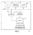
- Figure 1 is a block diagram of a preferred embodiment geometric modeling system 101 that includes a memory 104 where one or a plurality of geometric models are stored.
- One or more Central Processing Units (CPU) 102 access the model via the internal bus 105 and assist a graphics processor 103 in rendering the image and conveying it via the I/O subsystem 106 and the graphics accelerator 107 to the display 108.
- the internal bus 105 may be connected to a network interface to transmit the geometric models across a network to remote modeling systems.
- Figure 2 shows an example 200 of annotations draped onto the surface of a model 230.
- the geometry of the model defines the actual shape of the surface. In this example, the geometry represents an undulating surface.
- the attributes for this model are the colors that give it the appearance of a brick wall.
- the annotations, e.g. 205, 210 are the line segments that are draped onto the surface of the model. Here, as an example, line segments form a triangular mesh 205 and a curved line 210.
- the projected annotations 215, 220 maintain the same overall appearance as the original annotations 205, 210.
- Models 230 are well defined in the art, as are annotations. However, the prior art superimposes these annotations on the surface with distortions. The annotation draping process disclosed removes these distortions.
- Figure 3a is a close-up image 330 of the model in Figure 2, using the conventional prior art technique of texture maps to convey the annotation information.
- the annotations 340 are rendered and stored as an image and then texture mapped onto the model geometry.
- the annotations are distorted, appearing blurry and pixelized, due to the fixed resolution of the texture map, which causes a distracting artifact in the rendered image.
- the annotations appear very jagged when the viewer zooms into the image.
- the lack of fidelity in representing the annotation caused by the texture map in this example can lead the viewer to make incorrect conclusions about what is being seen.
- Figure 3b is a close-up image 350 of the model in Figure 2, using the current invention to drape the annotations 360 onto the model geometry. Since the annotations have been maintained as geometry, as opposed to texture maps, their appearance is cleanly preserved even at high magnification levels. As the viewer zooms into the model for a closer look, the annotations are rendered as geometry for the current viewing parameters and will therefore appear very smooth. They will not be seen as jagged, blurry edges, as in the prior art methods. The annotations are crisp and clean, and the viewer can more accurately determine what is being seen.
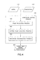
- Figure 4 is a flow chart of the novel annotation draping process 400.
- the process accepts as input a geometric model 410 and one or more annotations 420.
- the annotations are specified as geometry, in the form of a set of vertices V and a set of edges E, which connect the vertices within V together to form the edges of the annotations.
- the process 400 of draping the annotations onto the surface of the model comprises three stages, which are discussed in further detail below.
- the point projection process 430 projects the set of vertices V onto the surface of the model.
- the cutting plane selection process 440 chooses a plane for each edge of the annotations to define the path of the draped edge along the surface of the model.
- the annotation reconnection process 450 reconnects the projected vertices of the annotation edges, using the plane selected in the previous process 440, to preserve the original appearance of the annotations.
- the output 460 of the annotation draping process 400 is the geometric model with the annotations draped onto its surface.
- FIG. 5 is an image illustrating the point projection process 430.
- This first stage of the annotation draping process 400 projects the set of vertices V of the annotations onto the surface of the model.
- the surface of the model in this example comprises triangles, whose edges are shown as white line segments 510.
- the two vertices 525 of an edge 520 of an annotation are projected onto the surface of the model.
- Arrows 530 highlight the direction in which the annotation vertices 525 are projected onto the surface, resulting in two new vertices 555.
- the draped annotation edges appear as black line segments 540.
- epsilon based on a percentage of the average annotation edge length, that forces the projected vertices to snap first to the nearest surface vertex within epsilon of the projected vertex, and if no surface vertex is within that range, to snap the projected vertex to the nearest surface edge within the epsilon range. If the vertex does not snap to a surface vertex or edge, it simply projects directly into the nearest surface triangle.
- the annotation vertex 525 on the right of Figure 5 projects near to a triangle edge and snaps onto the edge, while the vertex 525 on the left does not snap and remains in the interior of the triangle. Note that the draped annotation edges 540 appear crooked due to the low angle of view and the creases between adjacent triangles; from above, the draped edges appear straight.
- Figure 6 shows a prior art technique in which the two projected vertices 555 of an annotation are directly connected without regard for the surface triangles 510 shown as white line segments.
- the resulting edge 620 shown using transparency, penetrates deeply into the surface. Alternatively, the edge could also float high above the surface. Either artifact stands out perceptually and would distort the information carried by the draped annotation.
- the current invention selects a cutting plane for each edge of the annotation to define the path of the draped edge along the surface of the model.
- the cutting plane selection process 440 defined using the flow chart in Figure 7, requires three inputs for each edge of the annotations: the original. annotation edge vertices (v0, v1) 705, the projected vertices (p0, p1) 710 from the point projection process 430 which correspond to v0 and v1 respectively, and the surface triangles (t0, t1) 715 that contain the projected vertices p0 and p1 respectively.
- the cutting plane must pass through the two projected vertices 710 of the annotation edge, however, with only two selected points, a plane cannot be defined.
- a third point must be selected. We do this by computing 720 the midpoint M of the original annotation edge between v0 and v1. Using p0, p1, and M, we can then compute 725 the cutting plane P for this annotation edge. In some instances, these three points may be collinear and not define a valid plane. We therefore must test 730 to see if P is valid. If P is not a valid plane, we use an alternative scheme that computes 735 the average normal N for the surface triangles t0 and t1. The surface normal indicates the direction in which the triangle is facing. Using p0, p1, and N, we can then recompute 740 the cutting plane P for the annotation edge. We complete the cutting plane selection process 440 by returning the valid cutting plane P.
- Figure 8 illustrates the cutting plane selection process 440.
- the original annotation edge 520 and vertices (v0, v1) 525 are shown, as well as the projected vertices (p0, p1) 555 that correspond to the original vertices.
- the midpoint 840 of the annotation edge is computed.
- the cutting plane 860 is then computed using the projected vertices 555 and the midpoint 840 of the original edge.
- Pseudo-code for the cutting plane selection process 440 is included below.
- the input of this process are the annotation edge vertices (vi, vj), the projected annotation edge vertices (pi, pj), and the surface triangles (ti, tj) that contain pi and pj.
- the ComputeCuttingPlane function takes three points as input and computes the plane containing these points. This function is well-known in the art.
- the InvalidPlane function which is also well-known, determines if the cutting plane is valid.
- the SelectNormal function chooses an appropriate normal to compute the cutting plane. This normal may be the normal of either of the surface triangles (ti, tj), or may be the average of the two surface normals.
- the valid cutting plane for the annotation edge is computed and returned by this process.
- the annotation reconnection process 450 For each of the original edges of the annotation, we must reconnect the projected vertices to form the new draped edges that conform to the surface geometry. We have referred to this process as the annotation reconnection process 450.
- This process illustrated in Figure 9, can be thought of as walking along the surface of the model, since our algorithm begins at one of the projected endpoints and walks from triangle to triangle, creating new edges as necessary, until the second projected endpoint is reached.
- the "surface walk" process is guided by the cutting plane P computed in the cutting plane selection process 440.
- the projected vertices 555 and cutting plane P are highlighted in Figure 9.
- the annotation reconnection process 450 will create new edge segments 920 as it walks from triangle to triangle along the surface of the model 510. In this example, the reconnection process has created six new edges which represent the draped original annotation edge.
- Pseudo-code for the annotation reconnection process 450 is included below.
- the input for this process are the projected annotation edge vertices (pi, pj), the surface triangles (ti, tj) that contain pi and pj, and the valid cutting plane (cutPlane) selected for this annotation edge.
- the IntersectSurfaceWithCutPlane function intersects the cutPlane with the surface triangle startTri.
- the routine computes and returns the intermediate point (tempPoint) and surface triangle (tempTri) during the surface walk from pi to pj.
- the OutputDrapedEdge routine stores the newly computed draped edge in the computer's memory for later rendering.
Landscapes
- Engineering & Computer Science (AREA)
- Physics & Mathematics (AREA)
- Computer Graphics (AREA)
- Software Systems (AREA)
- General Physics & Mathematics (AREA)
- Theoretical Computer Science (AREA)
- Computer Hardware Design (AREA)
- General Engineering & Computer Science (AREA)
- Geometry (AREA)
- Processing Or Creating Images (AREA)
- Image Generation (AREA)
- Controls And Circuits For Display Device (AREA)
Abstract
Description
- This invention relates to the field of geometric modeling. More specifically, the invention relates to computation, visualization and/or annotation of geometric models.
- In CAD/CAM (Computer Aided Design/Computer Aided Manufacturing) and many other industries, one needs to view and interact with three-dimensional (3D) models obtained from a local machine or a remote server. These 3D models contain both geometry and surface features. The geometry of a model defines its shape, typically as a set of vertices and their connectivity. The connectivity of a model defines how the vertices are connected together to form the surface of the model. For example, vertices are often connected together as triangles or quadrilaterals. These surface shapes are often referred to as polygons. The surface features of a model contain additional information in the form of attributes and annotations. The attributes refer to data values specified for the geometry of the model, such as colors or normals. These values may be specified for each of the vertices, for each of the polygons, or for each vertex/polygon pair, also referred to as a corner. Annotations are used to provide further information about the model, often in the form of line segments or text mapped onto the surface of the model. For example, if the 3D model was of a geographic region, the annotations could include the roads, rivers, cities, and their names, for that geographic region. Another example, within the CAD/CAM domain, is to highlight the original mesh structure, i.e. wireframe, of a geometric model. This mesh structure contains line segments, also known as edges, between the vertices of the model.
- There is a growing need to represent complex three-dimensional models by simplified versions that are less expensive to store in memory on a computer, faster to transmit across a network from one computer to another computer, and faster to render on a computer. To address this great need, many techniques have been developed to simplify a model with minimal loss in perceived quality. See, for example, U.S. Pat. No. 5,929,860 or the article "Surface Simplification Using Quadric Error Metrics," by M. Garland and P. Heckbert, in Computer Graphics Proceedings, Annual Conference Series, 1997, pages 209-216. Such techniques attempt to reduce the geometry of the model so that when the simplified model is rendered on a computer, the viewer will be able to perceive few, if any, differences as compared to a rendering of the original model. To accomplish this goal, many of the simplification techniques take the attributes of the model into account as well when simplifying the geometry. See, for example, U.S. Pat. No. 6,100,902; P. Cignoni, C. Montani, C. Rocchini, and R. Scopigno, "A General Method for Preserving Attribute Values on Simplified Meshes", Proceedings of IEEE Visualization, pages 59-66, 1998; M. Garland and P. Heckbert, "Simplifying Surfaces with Color and Texture Using Quadric Error Metrics," Proceedings of IEEE Visualization, pages 264-269, 1998; and H. Hoppe, "New Quadric Metric for Simplifying Meshes with Appearance Attributes," Proceedings of IEEE Visualization, pages 59-66, 1999. These techniques let the attributes guide the simplification process so that the geometry and the attributes of the simplified model appear the same as in the original model. To further preserve the overall appearance of the model, the annotations must be mapped onto the simplified model when simplification techniques are utilized, since the annotations can convey a significant amount of information.
- To convey information about a model to the viewer, there is clearly a need to map the annotations of the model onto its original surface, or a simplified version of its surface in those instances when simplification has been utilized. We often refer to this mapping operation as "draping" the annotations onto the surface of the model.
- Texture mapping, thoroughly described by P. Heckbert in "Survey of Texture Mapping", IEEE Computer Graphics and Applications, volume 6, number 11, pages 56-67, November 1986, refers to a technique for mapping an image onto the surface of a model. For example, let us say that we have a model of a wooden door. To convey the actual grain of the wood, we could include that within the model itself, however this would require a significant amount of additional geometry. To avoid this added complexity, texture mapping allows us to take a small image of the wood grain and map this onto the entire model so that the rendered image appears the same as if we used geometry to convey the wood grain.
- Texture mapping has been commonly used to map annotations onto the surface of a model. To accomplish this, the annotations are first rendered as an image and stored in the memory of a computer. When the model is being viewed, the texture map of the annotations is applied to the surface of the model to convey the additional information provided by the annotations. Using such an approach, the annotations of a model can be mapped onto the original or simplified surface of the model, since they are stored in the form of an image.
- Texture mapping requires specialized graphics hardware for adequate performance during viewing, and that hardware is not currently guaranteed to be present on all computers. In addition, texture mapping requires rendering one or more views of the annotations from different viewpoints, and projecting the rendered images onto the surface via texture coordinates. When multiple images are used to represent the annotations of the model at the same time, differences in rendering parameters between images may result in a discontinuity where the images border each other and this discontinuity can stand out as a disturbing artifact. Annotations that do not appear seamless may be hard to interpret because the eye is drawn to the abrupt changes in surface characteristics rather than the actual features on the surface. Consequently, the annotations may become an ineffective means for conveying the additional information to the viewer.
- Texture maps also suffer from blurring and pixelization at high magnification. Since the annotations are stored as an image, they are recorded at a fixed resolution. Typically the resolution of the image is measured in terms of the number of pixels in width and height. If the viewer zooms into the model to see the surface details more closely, the annotations texture map will appear blurry and unnatural. The end result is that the information conveyed by the annotations will be lost by the viewer.
- Texture maps are most efficient for simple geometric models. For complex models, many additional images, from different viewpoints, will be required. This will greatly exacerbate the discontinuity problem mentioned previously.
- An object of the embodiment of the invention is an improved system and method for draping, i.e., mapping, arbitrary annotations onto a surface.
- Another such object of this invention is an improved system and method for draping with an adequate amount of fidelity and with greater speed and simplicity.
- Another such object of this invention is an improved system and method for projecting the vertices of an annotation onto a surface and reconnecting the projected vertices to preserve the appearance of the original annotation on the surface.
- Yet a further such object of this invention is an improved system and method for reconnecting the projected vertices of an annotation using the projected vertices and the midpoint of the original annotation line segments.
- Vertices of an annotation are projected onto a surface of a (2D or3D) model and reconnected to preserve the original appearance of the annotation. The result of our method is a new set of geometry for the annotation that geometrically conforms to the surface of the model. A plane is defined by the midpoint of the original line segment and the two projected vertices. This plane is used to create the new line segments that conform to the surface, e.g. by doing a "surface walk" between the projected points along the line defined by the intersection of the plane and the surface.
- This invention solves the annotation mapping problem geometrically and the results do not require graphics hardware to visualize. Furthermore, the invention works well with arbitrary shapes and does not suffer from blurring under high magnification.
- By maintaining the annotations as geometry, as opposed to textures, we also are able to simplify them while still maintaining the overall appearance of the model over a wide range of magnifications . At the same time, the invention does not preclude texture maps from being used to provide attribute information, such as color.
- The foregoing and other objects, aspects, and advantages will be better understood from the following non-limiting detailed description of preferred embodiments of the invention with reference to the drawings that include the following:
- Figure 1 is a block diagram of a preferred system embodying the present invention;
- Figure 2 is an image showing an example of annotations draped onto the surface of a model;
- Figure 3a is a close-up image of the same model in Figure 2, using prior art texture maps to convey the annotation information;
- Figure 3b is a close-up image of the model in Figure 2, using the current invention to drape the annotations as geometry onto the model;
- Figure 4 is a flow chart showing an annotation draping process;
- Figure 5 is an image of the projection of the annotation vertices;
- Figure 6 is an image of prior art that directly connects the projected annotation vertices;
- Figure 7 is a flow chart showing the cutting plane selection process;
- Figure 8 is an image of the cutting plane used within the annotation reconnection process;
- Figure 9 is an image of a draped annotation on the surface of a model.
-
- Referring now to the drawings, and more particularly, Figure 1 is a block diagram of a preferred embodiment
geometric modeling system 101 that includes amemory 104 where one or a plurality of geometric models are stored. One or more Central Processing Units (CPU) 102 access the model via theinternal bus 105 and assist agraphics processor 103 in rendering the image and conveying it via the I/O subsystem 106 and thegraphics accelerator 107 to thedisplay 108. Optionally, theinternal bus 105 may be connected to a network interface to transmit the geometric models across a network to remote modeling systems. These components are all well-known. A novelannotation draping process 400, described in more detail in Figure 4, is executed by one or more of the CPUs. - Figure 2 shows an example 200 of annotations draped onto the surface of a
model 230. The geometry of the model defines the actual shape of the surface. In this example, the geometry represents an undulating surface. The attributes for this model are the colors that give it the appearance of a brick wall. The annotations, e.g. 205, 210, are the line segments that are draped onto the surface of the model. Here, as an example, line segments form atriangular mesh 205 and acurved line 210. After a novel draping process, described below, the projectedannotations original annotations Models 230 are well defined in the art, as are annotations. However, the prior art superimposes these annotations on the surface with distortions. The annotation draping process disclosed removes these distortions. - Figure 3a is a close-up
image 330 of the model in Figure 2, using the conventional prior art technique of texture maps to convey the annotation information. In this illustration, theannotations 340 are rendered and stored as an image and then texture mapped onto the model geometry. Under high magnification, the annotations are distorted, appearing blurry and pixelized, due to the fixed resolution of the texture map, which causes a distracting artifact in the rendered image. The annotations appear very jagged when the viewer zooms into the image. The lack of fidelity in representing the annotation caused by the texture map in this example can lead the viewer to make incorrect conclusions about what is being seen. - Figure 3b is a close-up
image 350 of the model in Figure 2, using the current invention to drape theannotations 360 onto the model geometry. Since the annotations have been maintained as geometry, as opposed to texture maps, their appearance is cleanly preserved even at high magnification levels. As the viewer zooms into the model for a closer look, the annotations are rendered as geometry for the current viewing parameters and will therefore appear very smooth. They will not be seen as jagged, blurry edges, as in the prior art methods. The annotations are crisp and clean, and the viewer can more accurately determine what is being seen. - Figure 4 is a flow chart of the novel
annotation draping process 400. The process accepts as input ageometric model 410 and one ormore annotations 420. The annotations are specified as geometry, in the form of a set of vertices V and a set of edges E, which connect the vertices within V together to form the edges of the annotations. Theprocess 400 of draping the annotations onto the surface of the model comprises three stages, which are discussed in further detail below. Thepoint projection process 430 projects the set of vertices V onto the surface of the model. The cuttingplane selection process 440 chooses a plane for each edge of the annotations to define the path of the draped edge along the surface of the model. Theannotation reconnection process 450 reconnects the projected vertices of the annotation edges, using the plane selected in theprevious process 440, to preserve the original appearance of the annotations. - The
output 460 of theannotation draping process 400 is the geometric model with the annotations draped onto its surface. - Figure 5 is an image illustrating the
point projection process 430. This first stage of theannotation draping process 400, described in Figure 4, projects the set of vertices V of the annotations onto the surface of the model. The surface of the model in this example comprises triangles, whose edges are shown aswhite line segments 510. In this illustration, the twovertices 525 of anedge 520 of an annotation are projected onto the surface of the model.Arrows 530 highlight the direction in which theannotation vertices 525 are projected onto the surface, resulting in twonew vertices 555. Upon completion of theannotation draping process 400, the draped annotation edges appear asblack line segments 540. - There are well-known prior art techniques for projecting arbitrary vertices onto a surface. In these techniques., the projection algorithm typically finds the nearest point on the surface to the original point. However, the criteria for projecting the vertices of an annotation are somewhat unique since one needs only a visually appropriate approximation of the projection, and one that avoids the creation of short segments during the
annotation reconnection process 450 that appear when a projected point lands near the vertex or edge of a surface triangle. To meet these special criteria, we use a tolerance value, epsilon, based on a percentage of the average annotation edge length, that forces the projected vertices to snap first to the nearest surface vertex within epsilon of the projected vertex, and if no surface vertex is within that range, to snap the projected vertex to the nearest surface edge within the epsilon range. If the vertex does not snap to a surface vertex or edge, it simply projects directly into the nearest surface triangle. Theannotation vertex 525 on the right of Figure 5 projects near to a triangle edge and snaps onto the edge, while thevertex 525 on the left does not snap and remains in the interior of the triangle. Note that the draped annotation edges 540 appear crooked due to the low angle of view and the creases between adjacent triangles; from above, the draped edges appear straight. - Once the annotation vertices are projected onto the surface of the model, the problem becomes how to reconnect them while conforming to the surface, yet retaining the straight appearance of the original annotation edges. Figure 6 shows a prior art technique in which the two projected
vertices 555 of an annotation are directly connected without regard for thesurface triangles 510 shown as white line segments. The resultingedge 620, shown using transparency, penetrates deeply into the surface. Alternatively, the edge could also float high above the surface. Either artifact stands out perceptually and would distort the information carried by the draped annotation. - The problem of finding the shortest path between two points which conforms to a surface is known to be computationally expensive (see J. Chen and Y. Han, "Shortest Paths on a Polyhedron", Proceedings of Sixth Annual Symposium on Computational Geometry, pages 360-369, 1990) and therefore cannot be used within a practical draping algorithm in a geometric modeling system. Since the goal is to efficiently produce a version of the annotation edges on the surface of the model that are visually consistent with the original, the requirement that the path be shortest in distance can be exchanged for a requirement that the path appear straight when viewed from somewhere above the surface.
- To fulfill this requirement, the current invention selects a cutting plane for each edge of the annotation to define the path of the draped edge along the surface of the model. The cutting
plane selection process 440, defined using the flow chart in Figure 7, requires three inputs for each edge of the annotations: the original. annotation edge vertices (v0, v1) 705, the projected vertices (p0, p1) 710 from thepoint projection process 430 which correspond to v0 and v1 respectively, and the surface triangles (t0, t1) 715 that contain the projected vertices p0 and p1 respectively. - The cutting plane must pass through the two projected
vertices 710 of the annotation edge, however, with only two selected points, a plane cannot be defined. To properly define the plane, a third point must be selected. We do this by computing 720 the midpoint M of the original annotation edge between v0 and v1. Using p0, p1, and M, we can then compute 725 the cutting plane P for this annotation edge. In some instances, these three points may be collinear and not define a valid plane. We therefore must test 730 to see if P is valid. If P is not a valid plane, we use an alternative scheme that computes 735 the average normal N for the surface triangles t0 and t1. The surface normal indicates the direction in which the triangle is facing. Using p0, p1, and N, we can then recompute 740 the cutting plane P for the annotation edge. We complete the cuttingplane selection process 440 by returning the valid cutting plane P. - Figure 8 illustrates the cutting
plane selection process 440. Theoriginal annotation edge 520 and vertices (v0, v1) 525 are shown, as well as the projected vertices (p0, p1) 555 that correspond to the original vertices. Using theoriginal vertices 525, themidpoint 840 of the annotation edge is computed. The cuttingplane 860 is then computed using the projectedvertices 555 and themidpoint 840 of the original edge. - Pseudo-code for the cutting
plane selection process 440 is included below. The input of this process are the annotation edge vertices (vi, vj), the projected annotation edge vertices (pi, pj), and the surface triangles (ti, tj) that contain pi and pj. The ComputeCuttingPlane function takes three points as input and computes the plane containing these points. This function is well-known in the art. The InvalidPlane function, which is also well-known, determines if the cutting plane is valid. The SelectNormal function chooses an appropriate normal to compute the cutting plane. This normal may be the normal of either of the surface triangles (ti, tj), or may be the average of the two surface normals. The valid cutting plane for the annotation edge is computed and returned by this process.
- For each of the original edges of the annotation, we must reconnect the projected vertices to form the new draped edges that conform to the surface geometry. We have referred to this process as the
annotation reconnection process 450. This process, illustrated in Figure 9, can be thought of as walking along the surface of the model, since our algorithm begins at one of the projected endpoints and walks from triangle to triangle, creating new edges as necessary, until the second projected endpoint is reached. The "surface walk" process is guided by the cutting plane P computed in the cuttingplane selection process 440. The projectedvertices 555 and cutting plane P are highlighted in Figure 9. Theannotation reconnection process 450 will createnew edge segments 920 as it walks from triangle to triangle along the surface of themodel 510. In this example, the reconnection process has created six new edges which represent the draped original annotation edge. - Pseudo-code for the
annotation reconnection process 450 is included below. The input for this process are the projected annotation edge vertices (pi, pj), the surface triangles (ti, tj) that contain pi and pj, and the valid cutting plane (cutPlane) selected for this annotation edge. The IntersectSurfaceWithCutPlane function intersects the cutPlane with the surface triangle startTri. The routine computes and returns the intermediate point (tempPoint) and surface triangle (tempTri) during the surface walk from pi to pj. The OutputDrapedEdge routine stores the newly computed draped edge in the computer's memory for later rendering.

- Alternative uses and methods of simplifying the results of this invention are disclosed and claimed in European patent application number xxx, entitled "SYSTEM AND METHOD FOR THE COORDINATED SIMPLIFICATION OF SURFACE AND WIRE-FRAME DESCRIPTIONS OF A GEOMETRIC MODEL" to Horn et. al, and European patent application number xxx, entitled "APPARATUS, SYSTEM, AND METHOD FOR SIMPLIFYING ANNOTATIONS ON A GEOMETRIC SURFACE" to Suits et. al, filed on the same day as this disclosure.
Claims (6)
- A method for annotating a surface of a computer model, comprising the steps of:projecting two or more annotation vertices, being projected vertices, of an annotation onto the surface of the model, the annotation having annotation edges that connect pairs of the annotation vertices;selecting a plane between a pair of the projected vertices, the plane being defined as containing the pair of the projected vertices and a midpoint of the annotation edge that connects the pair of the annotation vertices;cutting the surface of the model with the plane, the plane intersecting the model on a cutting line; andreconnecting the projected vertices on the surface of the model along the cutting line to produce the projection of the respective annotation edges on the model.
- A method, as in claim 1, where the projected vertices and the midpoint of the annotation edge are collinear and the plane is defined by containing the two projected vertices and a normal to the surface of the model at one or more of the projected vertices.
- A method, as in claim 1 or 2, where the projected vertices are projected on the surface within a tolerance by snapping.
- A method, as in claim 1, 2 or 3 where the reconnection process is a "surface walk".
- A computer system that annotates a surface of a computer model, comprising:means for projecting two or more annotation vertices, being projected vertices, of an annotation onto the surface of the model, the annotation having annotation edges that connect pairs of the annotation vertices;means for selecting a plane between a pair of the projected vertices, the plane being defined as containing the pair of the projected vertices and a midpoint of the annotation edge that connects the pair of the annotation vertices;means for cutting the surface of the model with the plane, the plane intersecting the model on a cutting line; andmeans for reconnecting the projected vertices on the surface of the model along the cutting line to produce the projection of the respective annotation edges on the model.
- A computer product having a program comprising the steps of:projecting two or more annotation vertices, being projected vertices, of an annotation onto the surface of the model, the annotation having annotation edges that connect pairs of the annotation vertices;selecting a plane between a pair of the projected vertices, the plane being defined as containing the pair of the projected vertices and a midpoint of the annotation edge that connects the pair of the annotation vertices;cutting the surface of the model with the plane, the plane intersecting the model on a cutting line; andreconnecting the projected vertices on the surface of the model along the cutting line to produce the projection of the respective annotation edges on the model.
Applications Claiming Priority (2)
| Application Number | Priority Date | Filing Date | Title |
|---|---|---|---|
| US686780 | 2000-10-10 | ||
| US09/686,780 US6978230B1 (en) | 2000-10-10 | 2000-10-10 | Apparatus, system, and method for draping annotations on to a geometric surface |
Publications (2)
| Publication Number | Publication Date |
|---|---|
| EP1197921A2 true EP1197921A2 (en) | 2002-04-17 |
| EP1197921A3 EP1197921A3 (en) | 2003-11-26 |
Family
ID=24757724
Family Applications (1)
| Application Number | Title | Priority Date | Filing Date |
|---|---|---|---|
| EP01308538A Ceased EP1197921A3 (en) | 2000-10-10 | 2001-10-05 | Apparatus, system, and method for draping annotations on to a geometric surface |
Country Status (5)
| Country | Link |
|---|---|
| US (1) | US6978230B1 (en) |
| EP (1) | EP1197921A3 (en) |
| JP (1) | JP2002197484A (en) |
| CA (1) | CA2357971A1 (en) |
| TW (1) | TWI225224B (en) |
Families Citing this family (20)
| Publication number | Priority date | Publication date | Assignee | Title |
|---|---|---|---|---|
| US7069108B2 (en) | 2002-12-10 | 2006-06-27 | Jostens, Inc. | Automated engraving of a customized jewelry item |
| DE102004003134A1 (en) * | 2004-01-14 | 2005-08-04 | Hansgrohe Ag | Wall bracket for a hand shower |
| US8085266B2 (en) * | 2004-04-19 | 2011-12-27 | Jostens, Inc. | System and method for smoothing three dimensional images |
| US7688317B2 (en) * | 2006-05-25 | 2010-03-30 | Microsoft Corporation | Texture mapping 2-D text properties to 3-D text |
| US8126683B2 (en) | 2007-03-12 | 2012-02-28 | Jostens, Inc. | System and method for embellishment placement |
| US8773423B2 (en) * | 2007-05-07 | 2014-07-08 | Microsoft Corporation | Creating optimized gradient mesh of a vector-based image from a raster-based image |
| US8977377B2 (en) | 2010-02-25 | 2015-03-10 | Jostens, Inc. | Method for digital manufacturing of jewelry items |
| US9171396B2 (en) * | 2010-06-30 | 2015-10-27 | Primal Space Systems Inc. | System and method of procedural visibility for interactive and broadcast streaming of entertainment, advertising, and tactical 3D graphical information using a visibility event codec |
| EP2622582B1 (en) * | 2010-09-30 | 2019-01-02 | Koninklijke Philips N.V. | Image and annotation display |
| US9208265B2 (en) | 2011-12-02 | 2015-12-08 | Jostens, Inc. | System and method for jewelry design |
| JP6070006B2 (en) * | 2012-09-21 | 2017-02-01 | 富士通株式会社 | Verification support program, verification support method, and verification support apparatus |
| US9582615B2 (en) | 2013-01-16 | 2017-02-28 | Jostens, Inc. | Modeling using thin plate spline technology |
| CN104345691A (en) * | 2013-07-26 | 2015-02-11 | 鸿富锦精密工业(深圳)有限公司 | Calculating device and material processing simulation system and method |
| USD789228S1 (en) | 2013-11-25 | 2017-06-13 | Jostens, Inc. | Bezel for a ring |
| US9779528B2 (en) * | 2014-09-12 | 2017-10-03 | Microsoft Technology Licensing, Llc | Text realization |
| US9582616B2 (en) * | 2015-01-23 | 2017-02-28 | Siemens Product Lifecycle Management Software Inc. | Method for representing and generating a flat pattern for a composite ply that folds over itself |
| US11481529B2 (en) * | 2020-04-24 | 2022-10-25 | The Boeing Company | Section measurement system |
| CN113778281B (en) * | 2021-09-16 | 2024-06-21 | 联想(北京)有限公司 | Auxiliary information generation method, device, electronic device and storage medium |
| CN118172354A (en) * | 2024-04-15 | 2024-06-11 | 杭州海康机器人股份有限公司 | Defect point correction method, device and electronic equipment |
| US20260087740A1 (en) * | 2024-09-24 | 2026-03-26 | Roblox Corporation | Merging coplanar convex polygons in constructive solid geometry (csg) |
Family Cites Families (17)
| Publication number | Priority date | Publication date | Assignee | Title |
|---|---|---|---|---|
| GB8828342D0 (en) * | 1988-12-05 | 1989-01-05 | Rediffusion Simulation Ltd | Image generator |
| US5243665A (en) * | 1990-03-07 | 1993-09-07 | Fmc Corporation | Component surface distortion evaluation apparatus and method |
| US5448686A (en) | 1992-01-02 | 1995-09-05 | International Business Machines Corporation | Multi-resolution graphic representation employing at least one simplified model for interactive visualization applications |
| JP3556969B2 (en) * | 1994-06-20 | 2004-08-25 | 富士通株式会社 | Projection drawing method |
| US5526478A (en) * | 1994-06-30 | 1996-06-11 | Silicon Graphics, Inc. | Three dimensional model with three dimensional pointers and multimedia functions linked to the pointers |
| US5907850A (en) * | 1994-12-23 | 1999-05-25 | Gary Matthew Krause | Method and system for manipulating construction blueprint documents with hypermedia hotspot reference links from a first construction document to a related secondary construction document |
| US5845288A (en) * | 1995-12-11 | 1998-12-01 | Xerox Corporation | Automated system for indexing graphical documents having associated text labels |
| US5963209A (en) | 1996-01-11 | 1999-10-05 | Microsoft Corporation | Encoding and progressive transmission of progressive meshes |
| JPH10134208A (en) | 1996-10-31 | 1998-05-22 | Sony Corp | Shape data approximation method and drawing apparatus |
| US6260000B1 (en) * | 1997-11-04 | 2001-07-10 | Minolta Co., Ltd. | Three-dimensional shape data processing apparatus |
| US6256039B1 (en) * | 1998-08-14 | 2001-07-03 | The Board Of The Leland Stanford Junior University | Methods for manipulating curves constrained to unparameterized surfaces |
| US6525731B1 (en) * | 1999-11-09 | 2003-02-25 | Ibm Corporation | Dynamic view-dependent texture mapping |
| US6611725B1 (en) * | 2000-02-03 | 2003-08-26 | Solidworks Corporation | Computer drawing system |
| US6690371B1 (en) * | 2000-05-03 | 2004-02-10 | Ge Medical Systems Global Technology, Llc | Relevant image data extraction from a medical image data volume |
| US6633290B1 (en) * | 2000-05-18 | 2003-10-14 | Cyra Technologies, Inc. | Apparatus and method for forming 2D views of a structure from 3D point data |
| US6570568B1 (en) * | 2000-10-10 | 2003-05-27 | International Business Machines Corporation | System and method for the coordinated simplification of surface and wire-frame descriptions of a geometric model |
| US6518964B1 (en) * | 2000-10-10 | 2003-02-11 | International Business Machines Corporation | Apparatus, system, and method for simplifying annotations on a geometric surface |
-
2000
- 2000-10-10 US US09/686,780 patent/US6978230B1/en not_active Expired - Lifetime
-
2001
- 2001-09-28 CA CA002357971A patent/CA2357971A1/en not_active Abandoned
- 2001-10-02 JP JP2001305951A patent/JP2002197484A/en active Pending
- 2001-10-05 EP EP01308538A patent/EP1197921A3/en not_active Ceased
- 2001-10-05 TW TW090124675A patent/TWI225224B/en not_active IP Right Cessation
Non-Patent Citations (1)
| Title |
|---|
| SUITS F ET AL: "Simplification of surface annotations" PROCEEDINGS VISUALIZATION 2000. VIS 2000. SALT LAKE CITY, UT, OCT. 8 - 13, 2000, ANNUAL IEEE CONFERENCE ON VISUALIZATION, LOS ALAMITOS, CA: IEEE COMP. SOC, US, 8 October 2000 (2000-10-08), pages 235-242, XP010524608 ISBN: 0-7803-6478-3 * |
Also Published As
| Publication number | Publication date |
|---|---|
| CA2357971A1 (en) | 2002-04-10 |
| TWI225224B (en) | 2004-12-11 |
| US6978230B1 (en) | 2005-12-20 |
| JP2002197484A (en) | 2002-07-12 |
| EP1197921A3 (en) | 2003-11-26 |
Similar Documents
| Publication | Publication Date | Title |
|---|---|---|
| US6978230B1 (en) | Apparatus, system, and method for draping annotations on to a geometric surface | |
| US7532213B2 (en) | Bicubic surface real time tesselation unit | |
| US8711143B2 (en) | System and method for interactive image-based modeling of curved surfaces using single-view and multi-view feature curves | |
| CN101933049B (en) | Efficient geometric tessellation and displacement | |
| US7760201B2 (en) | Transfer of attributes between geometric surfaces of arbitrary topologies with distortion reduction and discontinuity preservation | |
| US7129943B2 (en) | System and method for feature-based light field morphing and texture transfer | |
| Mitani et al. | 3D sketch: sketch-based model reconstruction and rendering | |
| EP1026639A2 (en) | 3D computer graphics processing apparatus and method | |
| US20050140670A1 (en) | Photogrammetric reconstruction of free-form objects with curvilinear structures | |
| US11941746B2 (en) | Accurate smooth occluding contours | |
| US8947423B2 (en) | Direct 3-D drawing by employing camera view constraints | |
| JP2002042169A (en) | Three-dimensional image providing system and method, and morphing image providing system and method | |
| CA2357962C (en) | System and method for the coordinated simplification of surface and wire-frame descriptions of a geometric model | |
| Branch et al. | Automatic hole-filling of triangular meshes using local radial basis function | |
| JP4001733B2 (en) | Apparatus, system, and method for simplifying annotation on geometric surfaces | |
| Campen et al. | Walking on broken mesh: Defect‐tolerant geodesic distances and parameterizations | |
| Kadosh et al. | Tricubic interpolation of discrete surfaces for binary volumes | |
| Wu et al. | Photogrammetric reconstruction of free-form objects with curvilinear structures | |
| Phothong et al. | Quality improvement of 3D models reconstructed from silhouettes of multiple images | |
| González et al. | User-assisted simplification method for triangle meshes preserving boundaries | |
| Rigiroli et al. | Mesh refinement with color attributes | |
| Schilling et al. | Rendering of multiresolution models with texture | |
| Rajput | Error Analysis of 3D Polygonal Model: A Survey | |
| Kim et al. | Mesh simplification with vertex color | |
| CN114359504A (en) | Three-dimensional model display method and equipment |
Legal Events
| Date | Code | Title | Description |
|---|---|---|---|
| PUAI | Public reference made under article 153(3) epc to a published international application that has entered the european phase |
Free format text: ORIGINAL CODE: 0009012 |
|
| AK | Designated contracting states |
Kind code of ref document: A2 Designated state(s): AT BE CH CY DE DK ES FI FR GB GR IE IT LI LU MC NL PT SE TR |
|
| AX | Request for extension of the european patent |
Free format text: AL;LT;LV;MK;RO;SI |
|
| PUAL | Search report despatched |
Free format text: ORIGINAL CODE: 0009013 |
|
| AK | Designated contracting states |
Kind code of ref document: A3 Designated state(s): AT BE CH CY DE DK ES FI FR GB GR IE IT LI LU MC NL PT SE TR |
|
| AX | Request for extension of the european patent |
Extension state: AL LT LV MK RO SI |
|
| 17P | Request for examination filed |
Effective date: 20040510 |
|
| AKX | Designation fees paid |
Designated state(s): AT BE CH CY DE DK ES FI FR GB GR IE IT LI LU MC NL PT SE TR |
|
| 17Q | First examination report despatched |
Effective date: 20050331 |
|
| STAA | Information on the status of an ep patent application or granted ep patent |
Free format text: STATUS: THE APPLICATION HAS BEEN REFUSED |
|
| 18R | Application refused |
Effective date: 20090822 |