EP1197919A2 - System and method for simplifying geometric models - Google Patents
System and method for simplifying geometric models Download PDFInfo
- Publication number
- EP1197919A2 EP1197919A2 EP01308581A EP01308581A EP1197919A2 EP 1197919 A2 EP1197919 A2 EP 1197919A2 EP 01308581 A EP01308581 A EP 01308581A EP 01308581 A EP01308581 A EP 01308581A EP 1197919 A2 EP1197919 A2 EP 1197919A2
- Authority
- EP
- European Patent Office
- Prior art keywords
- description
- wire
- frame
- simplified
- geometric model
- Prior art date
- Legal status (The legal status is an assumption and is not a legal conclusion. Google has not performed a legal analysis and makes no representation as to the accuracy of the status listed.)
- Withdrawn
Links
Images





Classifications
-
- G—PHYSICS
- G06—COMPUTING OR CALCULATING; COUNTING
- G06T—IMAGE DATA PROCESSING OR GENERATION, IN GENERAL
- G06T17/00—Three-dimensional [3D] modelling for computer graphics
- G06T17/20—Finite element generation, e.g. wire-frame surface description, tesselation
Definitions
- This invention relates to the field of computer graphics. More specifically the invention relates to the simplification of geometric models for the purpose of display.
- geometric models are sometimes simultaneously represented by wire-frame and surface descriptions.
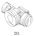
- a model may be displayed by using a surface description to render the surface and a wire-frame description to show sharp edges, as in Figure 2.
- the simultaneous use of surface and wire-frame descriptions of geometric models is also used for display purposes in other fields in MCAD.
- One such field is the application of numerical analysis to geometric models.
- finite element method geometric models are represented by an assembly of subdivisions called finite elements. Finite elements are interconnected at point locations called nodes. Within a finite element, the value of a dependent variable is completely determined by the value of the dependent variable at the nodes of the element.
- finite element analysis An assembly of finite elements is referred to as a finite element mesh. The finite element mesh serves as an alternate representation of the original real or abstract geometric model.
- graphical representations of the finite element mesh can be used to simultaneously communicate the structure of the finite element mesh, the surface of the finite element mesh (or geometric model) and the scalar magnitude of a solution component.
- polygons usually triangles
- line segments are used to represent the boundaries of individual elements
- color is used to represent the scalar magnitude of the solution component (e.g., temperature).
- the graphical result is obtained by combining a surface rendering with a line segment rendering.
- the surface rendering is used to represent the mesh surface and a scalar magnitude either representing or derived from a solution component.
- the shading is performed by applying shading algorithms. These shading algorithms use as input the geometry of the mesh surface and the color derived from the scalar magnitude of the solution component.
- the line segment rendering is generated from the edges of individual finite elements in the finite element mesh.
- the scalar magnitude of the solution component is frequently represented by a single color selected from a banded color map.
- the banded color map represents a contiguous range of scalar values with a single color.
- the final rendering usually takes one of two forms.
- One rendering mode referred to as the iso mode
- the other rendering mode referred to as the fringe mode
- the fringe mode uses one color corresponding to the scalar value to represent the face.
- K a simplicial complex of degree 2 specifying the connectivity of the mesh simplices
- D discrete scalar attributes
- S scalar attributes
- model descriptions also involve a wire-frame description of a geometric model (finite element mesh).
- a wire-frame description is represented by a subcomplex L K, where L is a degree 1 subcomplex of K .
- the visualization task is to render either the triple (K, L, V) or one of the quadruples ( K , L, V, D) (for the fringe rendering mode) or (K, L, V, S) (for the iso rendering mode).
- Figure 2 is a visualization of some triple (K, L, V).
- the graphical detail contained in a visualization is not always required for display. Furthermore, graphical detail may be reduced to increase the display rate by decreasing the required graphics processing.
- a variety of simplification techniques aimed at reducing the amount of graphics processing and increasing display rates by sacrificing geometric detail have been covered in the literature (see, for example, Garland and Heckbert, "Survey of Polygonal Surface Simplification Algorithms", Multiresolution Surface Modeling Course, SIGGRAPH-97). These simplification techniques reduce the graphics processing to increase the frame rates by rendering representations containing lower levels of geometric detail than the original geometric model.
- Factors such as the size in screen space of the rendered model, distance from the viewer, relative importance of the model, requested frame rate, relative motion between the viewer and the model, are used to select a simplified representation of the original model. All of these techniques attempt to produce a simplified model that, when rendered, retains as much image fidelity as possible with a rendering of the original model.
- Lindstrom and Turk (“Fast and memory efficient polygonal simplification”, IEEE Visualization '98 Proceedings, October 1998, 279-286) determine the vertex placement by minimizing the quadratic volume, boundary, and triangle shape objective functions, with the cost of edge collapse determined by the volume and boundary functions.
- Lindstrom (“Out-of-core simplification of large polygonal models", Computer Graphics Proceedings, Annual Conference Series, 2000, 259-262) has proposed a method extending the vertex clustering scheme of Rossignac and Borrel by using quadric error metrics to select the representative vertex for each cell in the uniform grid.
- Standard techniques exist to simultaneously display wire-frame and surface descriptions of geometric models.
- the complexity of the geometric model increases, the number of polygons and line segments that need to be rendered to convey the surface description and the wire-frame description grows, and it becomes increasingly difficult for the computer to render the visualization at the rates required for interactive inspection (3 Hz-30 Hz).
- Prior art techniques from geometric simplification to address the simplification of surface descriptions to increase interactive frame rates.
- Standard techniques also exist to simplify surface descriptions of geometric models while preserving certain edges.
- there are no prior art techniques which use a simplified surface description of a geometric model to simplify the wire-frame description of the model.
- prior art does not consider the problem of using computational results attached to a the geometric model to guide the simplification process when viewing results using the fringe mode of display.
- An object of the embodiment of the invention is a system and method for the accelerated rendering of surface and wire-frame descriptions of a geometric model by using a simplification of the surface description to guide the simplification of the wire-frame description.
- a object further search is a method to use the results obtained from a finite element analysis to guide the simplification of a surface.
- the present invention is a system for simplifying a geometric model to accelerate the rendering of the geometric model.
- a surface description of the geometric model is stored in one or more of the system memories.
- a wire-frame description of the geometric model is also stored.
- a surface simplification process alters the surface description to create an approximation of the original surface description.
- a wire-frame draping process drapes the wire-frame description onto the simplified surface and simplifies one or more of the line segments that are draped, the draped line segments being rendered over the simplified surface on the rendering device.
- FIG. 1 is a block diagram showing an overview of a typical environment using the present invention.
- the computer 101 comprises a memory 104 where one or a plurality of geometric models are stored.
- a CPU 102 accesses the model via the internal bus 105 and assists a graphics processor 103 in rendering the image and conveying it via the I/O subsystem 106 and the graphics accelerator 107 to the display 108.
- the present invention can be embodient on a system of Figure 1 that communicates over one or more networks.
- Figure 2 is prior art representation of a geometric model. These models and the techniques for creating and displaying these models are well known.
- Figure 3 illustrates a model displayed using conventional techniques ( Figures 3a and 3b) and the present invention ( Figures 3c and 3d).
- the original automobile surface and wire-frame descriptions consist, respectively, of 142988 triangles and 156632 edges of finite elements.
- Figure 3a demonstrates a prior art rendering of a triangulated surface (K,V) of the finite element mesh.
- K,V triangulated surface
- Figure 3b illustrates a rendering of the same surface along with the prior art edges of the finite elements (K, L, V).
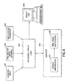
- Figure 4 provides an overview of the preferred application embodying the present invention.
- the Application Display Logic unit 404 determines a required simplification level .
- the simplifier 405 comprises the surface simplification module 407 and the line segment simplification module 408. Based on the requested level of simplification, the simplifier 405 generates the approximation to the original representation of the surface description and the wire-frame description . The approximation is sent back to the Application Display Logic unit 404, where it is then rendered on the display unit 406 at a higher frame rate than could have been achieved with the original surface and wire-frame descriptions.
- One key feature of the present invention is the use of the simplification of the surface description 407 to guide the simplification of the wire-frame description 408.
- Figure 5 details the coordinated simplification of the surface and wire-frame descriptions of a geometric model or finite element mesh as performed in the preferred embodiment of the current invention.
- the simplifier 405 represents the combined functionality of steps 505, 506 and 507 .
- the surface and wire-frame descriptions of the geometric model and/or finite element mesh 503 are extracted from a geometric model 501, a finite element mesh 510, or both.
- Color attributes may be mapped at step 509 onto the surface description 503 if an (optional) finite element analysis is performed at step 502.
- the solution component scalar and the color map are chosen by the user or a process at step 504.
- the solution component scalar is calculated in a finite element analysis 502 based on parameter input from 511 and the finite element mesh 510.
- the finite element mesh may be derived from a geometric model 501.
- the surface description is simplified at step 505 utilizing both prior art and elements of the current invention. Elements from the current invention are incorporated at step 503 if color attributes from step 509 are attached to the surface and if the fringe mode of display is chosen. These elements of the current invention are described in Figure 6.
- Another feature of the current invention is the optional use of the system to track the simplification of the surface description 505 to update the wire-frame description 506.
- step 507 techniques of "Draping” and “Annotation Simplification” are used to drape the wire-frame description. Updates in the wire-frame description performed in step 506 can be used to accelerate the process. The approximate wire-frame and surface descriptions of 507 are then available for display at step 508.
- One key feature of the present invention is the use of the simplification of the surface description 505 to support and guide the projection (draping) of the original wire-frame description 507.
- the mesh simplification of the surface description 505 is performed by repeating the edge collapse operation following the work of Garland and Heckbert.
- An objective function for evaluating the importance of the edge in the model is required to select the next edge for removal.
- a quadric error metric of Garland and Heckbert is used to evaluate the cost of the edge collapse.
- Figure 6 illustrates the simplification of the triangle mesh guided by the results of the finite element analysis.
- Figures 6a and 6b demonstrate the original triangle mesh.
- Figure 6c illustrates the surface of the simplified mesh.
- Figures 6d and 6e demonstrate the simplified triangle meshes obtained using the two approaches.
- the cylinder model contains 67680 triangles; the simplified models are both comprised of 16000 triangles.
- the wire-frame draping and simplification procedures are performed in step 507.
- the vertices of the wire-frame description are projected onto the simplified surface, and the projected vertices are reconnected to preserve the original appearance of the line segments.
- the projection of the vertices may be optionally assisted and accelerated by maintaining the correspondence between the vertices of the original surface description of the model and the vertices of the simplified surface description of the model.
- the mapping f reduces the computational expense of the vertex projection operation during the draping of the wire-frame description onto the simplified surface description.
- the vertex projection of a vertex v of the wire-frame description of a model is evaluated only for the triangles that are incident on the vertex f (v) of the simplified surface description. Of these projections, the projection closest to the vertex v is chosen as the projection of the vertex v onto the simplified surface.
- "Draping" is used to reconnect the projected vertices for each line segment of the wire-frame description.
- a plane is defined by the midpoint of the original line segment and the two projected endpoints. This plane is used to create the new line segments that conform to the surface of the simplified mesh.
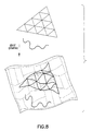
- Figure 8 illustrates the edge draping operation. The result of this process is a new set of geometry for the edges of the wire-frame description that geometrically conforms to the surface of the mesh.
- edges produce at least as many vertices and edges as the original annotation.
- many of the projected edges are not only coplanar, but also nearly collinear. This calls for an edge simplification technique.
- the algorithm used in the preferred embodiment is based on the "Annotation Simplification". It alters the topology of the annotation without significantly affecting the appearance. For rendering purposes, it is important that the edges remain close to the surface description without penetrating it, while edge position errors within the plane are much less noticeable.
- the approach is based on directed, asymmetric tolerance. For each of the walked edges, an asymmetric tolerance window is constructed.
Landscapes
- Physics & Mathematics (AREA)
- Engineering & Computer Science (AREA)
- Computer Graphics (AREA)
- Geometry (AREA)
- Software Systems (AREA)
- General Physics & Mathematics (AREA)
- Theoretical Computer Science (AREA)
- Image Generation (AREA)
- Processing Or Creating Images (AREA)
Abstract
Description
- This invention relates to the field of computer graphics. More specifically the invention relates to the simplification of geometric models for the purpose of display.
- In the field of mechanical computer aided design (MCAD), geometric models are sometimes simultaneously represented by wire-frame and surface descriptions. For example, a model may be displayed by using a surface description to render the surface and a wire-frame description to show sharp edges, as in Figure 2. The simultaneous use of surface and wire-frame descriptions of geometric models is also used for display purposes in other fields in MCAD. One such field is the application of numerical analysis to geometric models.
- Numerical methods are frequently used to simulate the response of geometric models to a diverse variety of imposed environments. In one popular numerical method known as the finite element method, geometric models are represented by an assembly of subdivisions called finite elements. Finite elements are interconnected at point locations called nodes. Within a finite element, the value of a dependent variable is completely determined by the value of the dependent variable at the nodes of the element. The use of the finite element method to simulate real-world problems is commonly referred to as finite element analysis. An assembly of finite elements is referred to as a finite element mesh. The finite element mesh serves as an alternate representation of the original real or abstract geometric model.
- It is common practice to use graphical representations of the finite element mesh and one or more computed results to examine a solution obtained from a finite element analysis. For finite element meshes composed of 2-dimensional or 3-dimensional elements embedded in the 3-dimensional Euclidean space, graphical representations can be used to simultaneously communicate the structure of the finite element mesh, the surface of the finite element mesh (or geometric model) and the scalar magnitude of a solution component. Here polygons (usually triangles) are used to represent the surface of the mesh, line segments are used to represent the boundaries of individual elements, and color is used to represent the scalar magnitude of the solution component (e.g., temperature). Typically, the graphical result is obtained by combining a surface rendering with a line segment rendering. The surface rendering is used to represent the mesh surface and a scalar magnitude either representing or derived from a solution component. The shading is performed by applying shading algorithms. These shading algorithms use as input the geometry of the mesh surface and the color derived from the scalar magnitude of the solution component. The line segment rendering is generated from the edges of individual finite elements in the finite element mesh. The scalar magnitude of the solution component is frequently represented by a single color selected from a banded color map. The banded color map represents a contiguous range of scalar values with a single color. The final rendering usually takes one of two forms. One rendering mode, referred to as the iso mode, is used to represent scalar values attached to nodes and permits intra-finite element transitions from a color representing one scalar value to a color representing another scalar value. The other rendering mode, referred to as the fringe mode, is used to represent scalar values attached to 2-dimensional faces in the mesh. The fringe mode uses one color corresponding to the scalar value to represent the face.
- Most of the existing techniques for visualizing surface descriptions of the geometric models utilize triangle meshes. The geometry of a triangle mesh refers to the pair (K,V), where K is a simplicial complex of degree 2 specifying the connectivity of the mesh simplices, and V = {v1 , ..., vm} is the set of vertex positions vi = (xi , yi, zi) defining the shape of the mesh in R3. In the FEM applications, there are either discrete scalar attributes D associated with the faces of the mesh, or scalar attributes S associated with the vertices of the mesh. In the FEM analysis, model descriptions also involve a wire-frame description of a geometric model (finite element mesh). A wire-frame description is represented by a subcomplex LK, where L is a degree 1 subcomplex of K. The visualization task is to render either the triple (K, L, V) or one of the quadruples (K, L, V, D) (for the fringe rendering mode) or (K, L, V, S) (for the iso rendering mode). For example, Figure 2 is a visualization of some triple (K, L, V).

- The graphical detail contained in a visualization is not always required for display. Furthermore, graphical detail may be reduced to increase the display rate by decreasing the required graphics processing. A variety of simplification techniques aimed at reducing the amount of graphics processing and increasing display rates by sacrificing geometric detail have been covered in the literature (see, for example, Garland and Heckbert, "Survey of Polygonal Surface Simplification Algorithms", Multiresolution Surface Modeling Course, SIGGRAPH-97). These simplification techniques reduce the graphics processing to increase the frame rates by rendering representations containing lower levels of geometric detail than the original geometric model. Factors such as the size in screen space of the rendered model, distance from the viewer, relative importance of the model, requested frame rate, relative motion between the viewer and the model, are used to select a simplified representation of the original model. All of these techniques attempt to produce a simplified model that, when rendered, retains as much image fidelity as possible with a rendering of the original model.
- There exist several techniques that address the simplification of meshes. In most approaches, the initial meshes are replaced by approximations with fewer faces which produce visually similar results, thereby improving rendering efficiency. Rossignac and Borrel ("Multi-resolution 3D approximations for rendering complex scenes", Modeling in Computer Graphics, 455-465 (Springer-Verlag 1993) and US Patent 5,448,686) proposed one of the earliest simplification algorithms. Their algorithm divides the model into cells of a uniform rectangular grid, and replaces all vertices within the grid cell by a single representative vertex.
- The edge collapse operation has been used extensively in simplification, and it generally produces higher quality results. Garland and Heckbert ("Surface simplification using quadric error metrics", Computer Graphics Proceedings, Annual Conference Series, 1997, 209-216) maintain a 4 by 4 symmetric matrix at each vertex that allows to track square distances to the faces of the original model. They subsequently generalized the quadric error metric to support simplification of surfaces with color and texture ("Simplifying surfaces with color and texture using quadric error metrics", IEEE Visualization '98 Proceedings, October 1998, 263-269). Lindstrom and Turk ("Fast and memory efficient polygonal simplification", IEEE Visualization '98 Proceedings, October 1998, 279-286) determine the vertex placement by minimizing the quadratic volume, boundary, and triangle shape objective functions, with the cost of edge collapse determined by the volume and boundary functions. Lindstrom ("Out-of-core simplification of large polygonal models", Computer Graphics Proceedings, Annual Conference Series, 2000, 259-262) has proposed a method extending the vertex clustering scheme of Rossignac and Borrel by using quadric error metrics to select the representative vertex for each cell in the uniform grid.
- Standard techniques exist to simultaneously display wire-frame and surface descriptions of geometric models. However, as the complexity of the geometric model increases, the number of polygons and line segments that need to be rendered to convey the surface description and the wire-frame description grows, and it becomes increasingly difficult for the computer to render the visualization at the rates required for interactive inspection (3 Hz-30 Hz). It is obvious to use prior art techniques from geometric simplification to address the simplification of surface descriptions to increase interactive frame rates. Standard techniques also exist to simplify surface descriptions of geometric models while preserving certain edges. However, there are no prior art techniques which use a simplified surface description of a geometric model to simplify the wire-frame description of the model. Furthermore, prior art does not consider the problem of using computational results attached to a the geometric model to guide the simplification process when viewing results using the fringe mode of display.
- An object of the embodiment of the invention is a system and method for the accelerated rendering of surface and wire-frame descriptions of a geometric model by using a simplification of the surface description to guide the simplification of the wire-frame description.
- A object further search is a method to use the results obtained from a finite element analysis to guide the simplification of a surface.
- The present invention is a system for simplifying a geometric model to accelerate the rendering of the geometric model. A surface description of the geometric model is stored in one or more of the system memories. A wire-frame description of the geometric model is also stored. A surface simplification process alters the surface description to create an approximation of the original surface description. A wire-frame draping process drapes the wire-frame description onto the simplified surface and simplifies one or more of the line segments that are draped, the draped line segments being rendered over the simplified surface on the rendering device.
- The foregoing and other objects, aspects, and advantages will be better understood from the following non-limiting detailed description of preferred embodiments of the invention with reference to the drawings that include the following:
- Figure 1 is a block diagram of a preferred system embodying the present invention;
- Figure 2 illustrates simultaneous rendering of a surface description of a geometric model and a wire-frame description of the same model using prior art;
- Figure 3 illustrates a model displayed according to the conventional technique (Figures 3a and 3b) and the present invention (Figures 3c and 3d).
- Figure 4 provides an overview for the preferred application embodying the present invention;
- Figure 5 is a flow chart detailing the coordinated simplification of the surface and wire-frame descriptions of a geometric model for the purpose of display, according to the embodiment of the present invention;
- Figure 6, comprising Figures 6a-6e, illustrates a fringe mode display created using the original surface description (Figure 6a), with a triangulated surface (Figure 6b), a fringe mode display using a simplified surface description (Figure 6c), the simplified surface with no simplification performed on boundaries (Figure 6d), and a simplified surface where simplification was aided by additional geometric constraints on boundaries (Figure 6e);
- Figure 7 demonstrates the vertex mapping procedure during a series of edge collapse operations;
- Figure 8 illustrates the line segment draping operation.
-
- Figure 1 is a block diagram showing an overview of a typical environment using the present invention. The
computer 101 comprises amemory 104 where one or a plurality of geometric models are stored. ACPU 102 accesses the model via theinternal bus 105 and assists agraphics processor 103 in rendering the image and conveying it via the I/O subsystem 106 and thegraphics accelerator 107 to thedisplay 108. The present invention can be embodient on a system of Figure 1 that communicates over one or more networks. - Figure 2 is prior art representation of a geometric model. These models and the techniques for creating and displaying these models are well known.
- Figure 3 illustrates a model displayed using conventional techniques (Figures 3a and 3b) and the present invention (Figures 3c and 3d). The original automobile surface and wire-frame descriptions consist, respectively, of 142988 triangles and 156632 edges of finite elements. Figure 3a demonstrates a prior art rendering of a triangulated surface (K,V) of the finite element mesh. In this figure, and in Figure 3c, the boundaries of triangles have been rendered to show the structure of the surface description. Figure 3b illustrates a rendering of the same surface along with the prior art edges of the finite elements (K, L, V).
- In Figure 3c, the surface representation of the original finite element mesh (Figure 3a) has been simplified, reducing the number of triangles to 35001 . Any appropriate prior art simplification technique can be used. For examples see the description of Figure 5 below.
- In Figure 3d, the line segments forming the edges of the finite elements have been draped onto the simplified surface of Figure 3c, and, with the help of an edge simplification process, the edge count has been reduced to 98146. The image fidelities of Figures 3b (original) and 3d (simplified) are comparable, and the reduction of the triangle and edge counts yields a significant reduction in rendering time.
- Figure 4 provides an overview of the preferred application embodying the present invention. Given the
geometric model 401, the results of the finite element method analysis 402 (optional), and application-specific parameters 403, the ApplicationDisplay Logic unit 404 determines a required simplification level . Thesimplifier 405 comprises thesurface simplification module 407 and the linesegment simplification module 408. Based on the requested level of simplification, thesimplifier 405 generates the approximation to the original representation of the surface description and the wire-frame description . The approximation is sent back to the ApplicationDisplay Logic unit 404, where it is then rendered on thedisplay unit 406 at a higher frame rate than could have been achieved with the original surface and wire-frame descriptions. One key feature of the present invention is the use of the simplification of thesurface description 407 to guide the simplification of the wire-frame description 408. - Figure 5 details the coordinated simplification of the surface and wire-frame descriptions of a geometric model or finite element mesh as performed in the preferred embodiment of the current invention. The
simplifier 405 represents the combined functionality ofsteps finite element mesh 503 are extracted from ageometric model 501, afinite element mesh 510, or both. Color attributes may be mapped atstep 509 onto thesurface description 503 if an (optional) finite element analysis is performed atstep 502. The solution component scalar and the color map are chosen by the user or a process atstep 504. The solution component scalar is calculated in afinite element analysis 502 based on parameter input from 511 and thefinite element mesh 510. The finite element mesh may be derived from ageometric model 501. The surface description is simplified atstep 505 utilizing both prior art and elements of the current invention. Elements from the current invention are incorporated atstep 503 if color attributes fromstep 509 are attached to the surface and if the fringe mode of display is chosen. These elements of the current invention are described in Figure 6. Another feature of the current invention is the optional use of the system to track the simplification of thesurface description 505 to update the wire-frame description 506. - European patent application number 09/686,780, entitled "APPARATUS, SYSTEM, AND METHOD FOR DRAPING ANNOTATIONS ON TO A GEOMETRIC SURFACE" to Klosowski et. al (hereafter "Draping") and European patent application number 09/686,643, entitled "APPARATUS, SYSTEM, AND METHOD FOR SIMPLIFYING ANNOTATIONS ON A GEOMETRIC SURFACE" to Suits et. al (hereafter "Annotation Simplification"), which are filed on the same day as this disclosure and are herein incorporated by reference in their entirety.
- At
step 507, techniques of "Draping" and "Annotation Simplification" are used to drape the wire-frame description. Updates in the wire-frame description performed instep 506 can be used to accelerate the process. The approximate wire-frame and surface descriptions of 507 are then available for display atstep 508. - One key feature of the present invention is the use of the simplification of the
surface description 505 to support and guide the projection (draping) of the original wire-frame description 507. There are no prior art techniques which use simplification of the surface description to guide the draping of the wire-frame description onto the simplified surface. Next, we discuss the details of the of the coordinated simplification of the surface description and the wire-frame draping and simplification performed atsteps 505 through 507. - In the preferred embodiment, the mesh simplification of the
surface description 505 is performed by repeating the edge collapse operation following the work of Garland and Heckbert. An objective function for evaluating the importance of the edge in the model is required to select the next edge for removal. In the illustrated embodiment, a quadric error metric of Garland and Heckbert is used to evaluate the cost of the edge collapse. - However, if the fringe rendering mode is being used to display the results, then we prohibit the collapse of the edges that are incident on the triangles of different color. Alternatively, we introduce geometric constraints that restrict the simplification of such edges.
- Figure 6 illustrates the simplification of the triangle mesh guided by the results of the finite element analysis. Figures 6a and 6b demonstrate the original triangle mesh. Figure 6c illustrates the surface of the simplified mesh. Figures 6d and 6e demonstrate the simplified triangle meshes obtained using the two approaches. The cylinder model contains 67680 triangles; the simplified models are both comprised of 16000 triangles.
- The wire-frame draping and simplification procedures are performed in
step 507. The vertices of the wire-frame description are projected onto the simplified surface, and the projected vertices are reconnected to preserve the original appearance of the line segments. The projection of the vertices may be optionally assisted and accelerated by maintaining the correspondence between the vertices of the original surface description of the model and the vertices of the simplified surface description of the model. - This vertex mapping procedure is illustrated on Figure 7. The mapping f between the vertex sets is maintained at
step 506 as follows: - (1) for the original surface description of the model, f is set to be the identity mapping;
- (2) if an edge (v0, v1) has been collapsed to a vertex v0, then put f(v1) = v0. Also, for all vertices v with f(v) = v1, put f(v) = v0.
-
- Hence, if a vertex v is removed from the simplified surface description, then the mapping f tracks the vertex of the simplified surface f(v) that has been identified with the vertex v after a sequence of edge collapse operations. If Figure 7, as a result of collapsing the edge (v1, v4), the vertex v4 is identified with the vertex v1 and is removed from the surface description. Thus, f(v4 ) = v1. After the collapse of the edge (v0, v1), the vertex v1 is also removed from the simplified surface, and we set f(v1 ) = v0. As a result of the second edge collapse, the vertex v4 has also been identified with the vertex v0 of the simplified surface. Since the vertex v1 is no longer on the simplified surface, we set f(v4 ) = v0.
- The mapping f reduces the computational expense of the vertex projection operation during the draping of the wire-frame description onto the simplified surface description. The vertex projection of a vertex v of the wire-frame description of a model is evaluated only for the triangles that are incident on the vertex f(v) of the simplified surface description. Of these projections, the projection closest to the vertex v is chosen as the projection of the vertex v onto the simplified surface.
- In the preferred embodiment, "Draping" is used to reconnect the projected vertices for each line segment of the wire-frame description. A plane is defined by the midpoint of the original line segment and the two projected endpoints. This plane is used to create the new line segments that conform to the surface of the simplified mesh. Figure 8 illustrates the edge draping operation. The result of this process is a new set of geometry for the edges of the wire-frame description that geometrically conforms to the surface of the mesh.
- The process of draping, or walking, the edges produces at least as many vertices and edges as the original annotation. On the simplified surface, where multiple triangles have been merged into one, many of the projected edges are not only coplanar, but also nearly collinear. This calls for an edge simplification technique. The algorithm used in the preferred embodiment is based on the "Annotation Simplification". It alters the topology of the annotation without significantly affecting the appearance. For rendering purposes, it is important that the edges remain close to the surface description without penetrating it, while edge position errors within the plane are much less noticeable. The approach is based on directed, asymmetric tolerance. For each of the walked edges, an asymmetric tolerance window is constructed. The simplification of adjacent edges is guided by the projections of the endpoints onto the plane of the tolerance window, and pivoting the tolerance window as it slides along the simplified edges. This allows greater edge simplification along the simplified surface description than perpendicular to it, and produces a simplified annotation that conforms to the surface yet contains far fewer edges than the original annotation.
Claims (11)
- A computer system for accelerating the rendering of a geometric model, the system comprising:one or more central processing units (CPUs), one or more memories, and one or more rendering devices;a surface description of the geometric model that is stored in one or more of the memories;a wire-frame description of the geometric model that is stored in one or more of the memories;a surface simplification process that alters the surface description to create an approximation of the surface description to create a simplified surface description;a wire-frame draping process that drapes the wire-frame description onto the simplified surface description and then simplifies one or more line segments of the draped wire-frame description to create a simplified wire-frame description; anda display that renders the simplified wire-frame description.
- A system, as in claim 1, where the wire-frame description represents any one or more of the following: one or more edges of elements in a finite element mesh, one or more edges that emphasize a discontinuity of an attribute across an edge of any one or more of the following attributes: a face normal, a texture coordinate, and a color.
- A system, as in claim 1 or 2, where the surface simplification process includes any one or more of the following: the method of Garland and Heckbert, the method of Rossignac and Borrel, the method of Lindstrom and Turk, the method of Lindstrom, and a geometric simplification process.
- A system, as in claim 1, 2 or 3 where the surface simplification process is constrained by one or more attributes used in a fringe mode display.
- A system, as in any one of claims 1 to 4, where the wire-frame draping process is accelerated by tracking vertex identification associated with one or more edge collapses during the simplification of the surface description.
- A system, as in any one of claims 1 to 5, where the simplified wire-frame description and the simplified surface description are rendered together on the display.
- A method of accelerating the rendering of a geometric model comprising the steps of:storing a surface description of the geometric model;storing a wire-frame description of the geometric model;approximating the surface description to create a simplified surface description;draping the wire-frame description onto the simplified surface description; andsimplifying one or more line segments of the draped wire-frame description to create a simplified wire-frame description.
- A method, as in claim 7, further comprising the step of rendering the simplified wire-frame description.
- A method, as in claim 7 or 8, further comprising the step of:evaluating projections of one or more vertices of the wire-frame description only on one or more triangles that are incident on the respective vertex.
- A computer system for accelerating the rendering of the geometric model, the system comprising:means for storing a surface description of the geometric model;means for storing a wire-frame description of the geometric model;means for approximating the surface description to create a simplified surface description;means for draping the wire-frame description onto the simplified surface description; andmeans for simplifying one or more line segments of the draped wire-frame description to create a simplified wire-frame description.
- A computer program product having a program comprising the following steps:storing a surface description of the geometric model;storing a wire-frame description of the geometric model;approximating the surface description to create a simplified surface description;draping the wire-frame description onto the simplified surface description; andsimplifying one or more line segments of the draped wire-frame description to create a simplified wire-frame description.
Applications Claiming Priority (2)
| Application Number | Priority Date | Filing Date | Title |
|---|---|---|---|
| US09/686,720 US6570568B1 (en) | 2000-10-10 | 2000-10-10 | System and method for the coordinated simplification of surface and wire-frame descriptions of a geometric model |
| US686720 | 2000-10-10 |
Publications (2)
| Publication Number | Publication Date |
|---|---|
| EP1197919A2 true EP1197919A2 (en) | 2002-04-17 |
| EP1197919A3 EP1197919A3 (en) | 2004-08-18 |
Family
ID=24757449
Family Applications (1)
| Application Number | Title | Priority Date | Filing Date |
|---|---|---|---|
| EP01308581A Withdrawn EP1197919A3 (en) | 2000-10-10 | 2001-10-08 | System and method for simplifying geometric models |
Country Status (4)
| Country | Link |
|---|---|
| US (1) | US6570568B1 (en) |
| EP (1) | EP1197919A3 (en) |
| JP (1) | JP3650355B2 (en) |
| CA (1) | CA2357962C (en) |
Cited By (3)
| Publication number | Priority date | Publication date | Assignee | Title |
|---|---|---|---|---|
| EP1542168A1 (en) * | 2003-12-11 | 2005-06-15 | Matsushita Electric Industrial Co., Ltd. | Method of analyzing electronic components, device for analyzing electronic components and electronic components using these |
| CN104282040A (en) * | 2014-09-29 | 2015-01-14 | 北京航空航天大学 | Finite element preprocessing method for reconstructing three-dimensional entity model |
| CN104933234A (en) * | 2015-06-04 | 2015-09-23 | 株洲时代新材料科技股份有限公司 | Analysis method of torsion bar assembly in side rolling resistance torsion bar system of locomotive |
Families Citing this family (15)
| Publication number | Priority date | Publication date | Assignee | Title |
|---|---|---|---|---|
| US6978230B1 (en) * | 2000-10-10 | 2005-12-20 | International Business Machines Corporation | Apparatus, system, and method for draping annotations on to a geometric surface |
| JP4720964B2 (en) * | 2001-05-31 | 2011-07-13 | 日本電気株式会社 | FEM analysis method, program, and system |
| US20040054509A1 (en) * | 2002-09-12 | 2004-03-18 | Breit Stephen R. | System and method for preparing a solid model for meshing |
| JP4463597B2 (en) * | 2004-03-24 | 2010-05-19 | 富士通株式会社 | 3D drawing model generation method and program thereof |
| US7606688B2 (en) * | 2004-07-27 | 2009-10-20 | The Boeing Company | Object oriented finite element modeling tools |
| JP2006092195A (en) * | 2004-09-22 | 2006-04-06 | Sega Corp | Image processing apparatus and image processing method |
| US7646384B2 (en) * | 2005-03-31 | 2010-01-12 | Siemens Product Lifecycle Management Software Inc. | System and method to determine a simplified representation of a model |
| DE102006019917B4 (en) * | 2006-04-28 | 2013-10-10 | Airbus Operations Gmbh | Method and device for ensuring the dimensional accuracy of multi-segment structural structures during assembly |
| KR101520649B1 (en) * | 2008-01-21 | 2015-05-15 | 삼성전자 주식회사 | 3 Method and system for compressing and decoding mesh data with random accessibility in 3-dimensional mesh model |
| US8854366B1 (en) | 2010-03-24 | 2014-10-07 | University Of South Florida | Automated geometric representation of discrete point sets |
| EP3264286B1 (en) | 2016-06-28 | 2020-11-18 | Dassault Systèmes | Querying a database with morphology criterion |
| EP3321817B1 (en) * | 2016-11-14 | 2025-04-02 | Dassault Systèmes | Querying a database based on a parametric view function |
| US11281824B2 (en) | 2017-12-13 | 2022-03-22 | Dassault Systemes Simulia Corp. | Authoring loading and boundary conditions for simulation scenarios |
| GB202108778D0 (en) * | 2021-06-18 | 2021-08-04 | Pointfuse Ltd | Pointcloud processing, especially for use with building intelligence modelling (BIM) |
| CN115423980B (en) * | 2022-09-08 | 2023-12-29 | 如你所视(北京)科技有限公司 | Model display processing method, device and storage medium |
Family Cites Families (3)
| Publication number | Priority date | Publication date | Assignee | Title |
|---|---|---|---|---|
| US5448686A (en) | 1992-01-02 | 1995-09-05 | International Business Machines Corporation | Multi-resolution graphic representation employing at least one simplified model for interactive visualization applications |
| US5963209A (en) | 1996-01-11 | 1999-10-05 | Microsoft Corporation | Encoding and progressive transmission of progressive meshes |
| JPH10134208A (en) | 1996-10-31 | 1998-05-22 | Sony Corp | Shape data approximation method and drawing apparatus |
-
2000
- 2000-10-10 US US09/686,720 patent/US6570568B1/en not_active Expired - Lifetime
-
2001
- 2001-09-28 CA CA002357962A patent/CA2357962C/en not_active Expired - Fee Related
- 2001-10-08 EP EP01308581A patent/EP1197919A3/en not_active Withdrawn
- 2001-10-10 JP JP2001312623A patent/JP3650355B2/en not_active Expired - Fee Related
Non-Patent Citations (1)
| Title |
|---|
| None * |
Cited By (3)
| Publication number | Priority date | Publication date | Assignee | Title |
|---|---|---|---|---|
| EP1542168A1 (en) * | 2003-12-11 | 2005-06-15 | Matsushita Electric Industrial Co., Ltd. | Method of analyzing electronic components, device for analyzing electronic components and electronic components using these |
| CN104282040A (en) * | 2014-09-29 | 2015-01-14 | 北京航空航天大学 | Finite element preprocessing method for reconstructing three-dimensional entity model |
| CN104933234A (en) * | 2015-06-04 | 2015-09-23 | 株洲时代新材料科技股份有限公司 | Analysis method of torsion bar assembly in side rolling resistance torsion bar system of locomotive |
Also Published As
| Publication number | Publication date |
|---|---|
| CA2357962A1 (en) | 2002-04-10 |
| EP1197919A3 (en) | 2004-08-18 |
| JP2002183228A (en) | 2002-06-28 |
| US6570568B1 (en) | 2003-05-27 |
| JP3650355B2 (en) | 2005-05-18 |
| CA2357962C (en) | 2007-08-21 |
Similar Documents
| Publication | Publication Date | Title |
|---|---|---|
| US6570568B1 (en) | System and method for the coordinated simplification of surface and wire-frame descriptions of a geometric model | |
| Lindstrom et al. | Terrain simplification simplified: A general framework for view-dependent out-of-core visualization | |
| Xia et al. | Dynamic view-dependent simplification for polygonal models | |
| Duchaineau et al. | ROAMing terrain: Real-time optimally adapting meshes | |
| CN113496539B (en) | A Texture Mapping Method and System Based on 3D Mesh Model Parameter Design | |
| US7561156B2 (en) | Adaptive quadtree-based scalable surface rendering | |
| JP2013507679A (en) | Method and system capable of 3D printing of 3D object model | |
| US6978230B1 (en) | Apparatus, system, and method for draping annotations on to a geometric surface | |
| CN114972612A (en) | Image texture generation method based on three-dimensional simplified model and related equipment | |
| US10636210B2 (en) | Dynamic contour volume deformation | |
| CN116503577A (en) | Method and system for fast acquisition of 3D model of virtual simulation scene | |
| US7358969B2 (en) | Method and system for partitioning the surface of a three dimentional digital object model in order to map a texture | |
| US6518964B1 (en) | Apparatus, system, and method for simplifying annotations on a geometric surface | |
| CN120707771A (en) | Map data processing method, device, equipment and medium based on model reconstruction | |
| Erikson et al. | Simplification culling of static and dynamic scene graphs | |
| CN119540430A (en) | Three-dimensional graphics rendering method and device based on graph theory | |
| CN106716500A (en) | Program, information processing device, depth definition method, and recording medium | |
| Petkov et al. | Interactive visibility retargeting in vr using conformal visualization | |
| US12056823B2 (en) | Segmenting three-dimensional meshes in graphical applications based on detection of elongated shapes | |
| CN106408644A (en) | Three-dimensional control cage constructing method | |
| Runions et al. | Ribbons: A representation for point clouds | |
| US8189006B1 (en) | Caching attributes of surfaces without global parameterizations | |
| Mörwald et al. | Direct optimization of T-splines based on Multiview Stereo | |
| JP2024521377A (en) | Method for processing data representing a three-dimensional volumetric scene - Patents.com | |
| CN121788755A (en) | Method and apparatus for generating OBJ files based on layered depth images |
Legal Events
| Date | Code | Title | Description |
|---|---|---|---|
| PUAI | Public reference made under article 153(3) epc to a published international application that has entered the european phase |
Free format text: ORIGINAL CODE: 0009012 |
|
| AK | Designated contracting states |
Kind code of ref document: A2 Designated state(s): AT BE CH CY DE DK ES FI FR GB GR IE IT LI LU MC NL PT SE TR |
|
| AX | Request for extension of the european patent |
Free format text: AL;LT;LV;MK;RO;SI |
|
| PUAL | Search report despatched |
Free format text: ORIGINAL CODE: 0009013 |
|
| AK | Designated contracting states |
Kind code of ref document: A3 Designated state(s): AT BE CH CY DE DK ES FI FR GB GR IE IT LI LU MC NL PT SE TR |
|
| AX | Request for extension of the european patent |
Extension state: AL LT LV MK RO SI |
|
| 17P | Request for examination filed |
Effective date: 20050210 |
|
| AKX | Designation fees paid |
Designated state(s): AT BE CH CY DE DK ES FI FR GB GR IE IT LI LU MC NL PT SE TR |
|
| 17Q | First examination report despatched |
Effective date: 20060214 |
|
| STAA | Information on the status of an ep patent application or granted ep patent |
Free format text: STATUS: THE APPLICATION IS DEEMED TO BE WITHDRAWN |
|
| 18D | Application deemed to be withdrawn |
Effective date: 20070508 |