EP1197764A2 - Strain-stabilized birefringent crystal - Google Patents
Strain-stabilized birefringent crystal Download PDFInfo
- Publication number
- EP1197764A2 EP1197764A2 EP01308582A EP01308582A EP1197764A2 EP 1197764 A2 EP1197764 A2 EP 1197764A2 EP 01308582 A EP01308582 A EP 01308582A EP 01308582 A EP01308582 A EP 01308582A EP 1197764 A2 EP1197764 A2 EP 1197764A2
- Authority
- EP
- European Patent Office
- Prior art keywords
- block
- temperature
- strain
- light transmissive
- optical system
- Prior art date
- Legal status (The legal status is an assumption and is not a legal conclusion. Google has not performed a legal analysis and makes no representation as to the accuracy of the status listed.)
- Withdrawn
Links
Images


Classifications
-
- G—PHYSICS
- G02—OPTICS
- G02B—OPTICAL ELEMENTS, SYSTEMS OR APPARATUS
- G02B5/00—Optical elements other than lenses
- G02B5/30—Polarising elements
- G02B5/3083—Birefringent or phase retarding elements
-
- Y—GENERAL TAGGING OF NEW TECHNOLOGICAL DEVELOPMENTS; GENERAL TAGGING OF CROSS-SECTIONAL TECHNOLOGIES SPANNING OVER SEVERAL SECTIONS OF THE IPC; TECHNICAL SUBJECTS COVERED BY FORMER USPC CROSS-REFERENCE ART COLLECTIONS [XRACs] AND DIGESTS
- Y10—TECHNICAL SUBJECTS COVERED BY FORMER USPC
- Y10S—TECHNICAL SUBJECTS COVERED BY FORMER USPC CROSS-REFERENCE ART COLLECTIONS [XRACs] AND DIGESTS
- Y10S359/00—Optical: systems and elements
- Y10S359/90—Methods
Definitions
- This invention relates generally to birefringent crystals, and more particularly, to a temperature-stabilized birefringent crystal for use in stable, temperature-independent birefringent crystal interferometers.
- Interferometers form the basis of a number of important communications devices including interleavers, dispersion compensators, and periodic filters.
- the basic function of an interferometer is to split coherent light into two paths with possibly different propagation delays and then to recombine the light from these two paths.
- FSR interferometer free spectral range
- n i l i products must be stable to much better than one wavelength of light. At optical communications wavelengths, this leads to a stability requirement on the order of 10 nm, which is difficult to maintain. It is known in the art that a birefringent crystal interferometer (BCI) can be designed to provide such stable path lengths.
- BCI birefringent crystal interferometer
- the two "paths" are simply the optical paths of the two orthogonal linear polarizations propagating through the material. Since one polarisation experiences the extraordinary refractive index, n e , and the other the ordinary refractive index, n o , the path difference, also known as the retardance, is given by ⁇ nl , where the birefringence, ⁇ n , is given by n e -n o for a material having positive dielectric anisotropy.
- CTE coefficient of thermal expansion
- Kuochou Tai et al. teach cascading two crystals of different material in such a way that the two crystal BCI is independent of temperature.
- an appropriately selected Yttrium ortho-Vanadate (YVO 4 ) crystal followed by an appropriately selected rutile (TiO 2 ) crystal provides an interferometer that is stable to both thermal and mechanical perturbations.
- this pair of crystals is selected to have the desired FSR and to be temperature stable, they typically do not resonate precisely at the optical frequency of interest (typically a channel on the ITU grid).
- the current practice is to add a thin piece of quartz (typically in the range of 180 to 210 microns). Accordingly, each crystal pair must be measured and an appropriate quartz piece selected to adjust the resonant frequency.
- It is a further object of this invention is to provide an optical retardance system that can be used in a stable, temperature independent BCI for use in interleavers, periodic filters, and/ or dispersion compensators.
- the instant invention relates to a stable, temperature-insensitive birefringent crystal interferometer (BCI) that uses a single variety of crystal and that can be used in an interleaver, a periodic filter, and/or a dispersion compensator.
- BCI birefringent crystal interferometer
- the resulting device is cheaper, more robust, and has better performance.
- an optical system comprising: a first block of light transmissive uniaxial birefringent material having an input port and an output port, the material having a first retardance at a first temperature; and, straining means for inducing a strain in one of the first block and a second block of light transmissive material optically coupled to the first block, the strain induced for maintaining a second net retardance substantially unchanged from the first retardance at at least a second other temperature.
- a method for compensating a thermal drift of a birefringent material comprising the steps of: providing a first block of light transmissive birefringent material having a first retardance at a first temperature; and, maintaining a net retardance substantially equal to the first retardance at a second temperature by applying a stress to one of the first block of light transmissive birefringent material and a second block of light transmissive material.
- a method for compensating a thermal drift of a birefringent material comprising the steps of: providing a light transmissive element having a net retardance at a first temperature, the light transmissive element comprising a block of the birefringent material; and, maintaining the net retardance of the light transmissive element at a second other temperature by inducing a strain in at least part of the light transmissive element.
- net retardance refers to the net or total retardance in the spectral region of desired device operation.
- Fig. 1 there is shown a prior art optical system for use in a birefringent crystal interferometer (BCI) having two varieties of birefringent crystals.
- a first YVO 4 birefringent crystal 10 is disposed adjacent a second TiO 2 birefringent crystal 20.
- the composition and length of each birefringent crystal is selected to have a predetermined free spectral range (FSR) and to provide thermal stability.
- a quartz (SiO 2 ) plate 30 is disposed adjacent the second birefringent crystal 20 to adjust the resonant frequency of the interferometer by a small amount.
- Light is shown to propagate from left to right.
- the c axis of the crystal is in the plane perpendicular to the optical path.
- Fig. 2 there are shown two different embodiments of an optical system 100 for use in a birefringent crystal interferometer in accordance with the instant invention, having a single variety of birefringent crystal 110.
- Superior temperature stabilizing and frequency tuning of the BCI is accomplished by virtue of the elastooptic effect, wherein the birefringence of a material is changed by inducing a strain in the material.
- the birefringent crystal is temperature-stabilized by inducing a strain in one of the crystal and another optical element optically coupled to the crystal.
- a temperature-dependent, uniform, strain field depicted by thick arrows, is shown incident on a single birefringent crystal 110 in a direction transverse to the direction of optical propagation.
- the strain field induces a change in the birefringence of the crystal 110, and modifies the free spectral range (FSR) of the interferometer through equation 2.
- FSR free spectral range
- a separate compensating plate 120 fabricated from a normally isotropic material, such as a glass block, for providing a compensating, temperature dependent FSR.
- a normally isotropic material such as a glass block
- this embodiment has the disadvantage of a second optical component, it provides several advantages in terms of flexibility.
- both the material and the size of the glass 120 is selected to provide best performance. This is in contrast to the embodiment shown in Fig. 2a, wherein the material and length of the crystal 110 are constrained by the desired FSR through equation 1.
- this embodiment advantageously allows the crystal 110 to be strain free, thus reducing the chances of fracturing or otherwise damaging the crystal. Furthermore, since the crystal 110 is strain free, the choice of crystal and/or temperature range is based on efficiency, not on resistance to breakage or damage.
- strain-induced birefringence is proportional to strain to a high degree of accuracy.
- the temperature-induced change in the FSR is also nearly linear with temperature. Therefore, it is required that the strain change linearly with temperature in order to cancel out the temperature shift of the FSR.
- this is accomplished by constraining the crystal 110 in Fig. 2a or the glass block 120 in Fig. 2b, in a metal mount with a thermal expansion different than that of the crystal 110 or glass block 120.
- this embodiment provides a substantially compact and self-stabilized BCI.
- a mount 130 supporting an optical element 140 which is either the crystal 110 or glass plate 120.
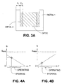
- the mount 130 which is preferably a single metal or a combination of metals, as for example shown in Fig. 3 a, is arranged to be in close contact with the optical element at all operating and storage temperatures of the device. As the temperature changes, the differing rates of thermal expansion of the optical element 140 and the metal mount 130 generate a strain in the optical element 140 that changes linearly with temperature, as required (i.e., the metal mount functions as straining means).
- a bi- or multi-metallic mount is designed such that the strain applied to the optic as a function of temperature is a function of the weighted average of the CTEs and dimensions of the metals, as well as the Young's moduli of all materials.
- the mount 130 is depicted as having three sides for surrounding the rectangularly shaped optical element 140, 2 or 4 sides are also possible.
- the three-sided design provides a one-piece construction that allows the optical element 140 to be easily placed therein.
- the mount provides at least two opposing sides for providing compressive strain in the crystal.
- the strain field throughout the element 140 is uniform in order to generate uniform birefringence and to reduce excess stress that could damage the optical element 140.
- a thin compliant layer between the mount and the crystal is optionally provided. This pad deforms in response to local non-uniform stress and therefore improves the uniformity of contact between the optical element 140 and the mount 130.
- the thermal conductivity of the mount 130 is preferably large to minimize any possible thermal gradients within the mount that create non-uniform loading of the crystal by the mount, or nonuniformities in temperature-dependence of the retardance of the optical material.
- strain fields in directions other than that intended be minimized.
- shear strain in the crystal due to the thermal expansion of the crystal and mount is preferably controlled.
- the corners of the optical element are optionally rounded or chamfered.
- the strain in the optical element 140 increases or decreases linearly with temperature.
- Figs. 4a and 4b the dependence of strain (S) on temperature (T) is shown.
- the sign of the slope in Figure 4 may be calculated by comparing the magnitude of the thermal expansion of the optical element 140 to that of the mount 130. For example, if the mount has a larger thermal expansion than the optical element then the strain will decrease with increasing temperature (Fig. 4a), whereas if the thermal expansion of the mount is smaller than the thermal expansion of the optical element then the strain will increase linearly with temperature (Fig. 4b).
- the pre-load at room temperature (marked by a star) is set so that, over the storage temperature range of the device, the strain never exceeds the damage threshold of the material or decreases lower than zero, the latter of which causes the mount 130 and the optical element 140 to separate.
- This pre-load has the second important property of adjusting the resonant frequency of the BCI, in analogy to the quartz plate 30 described in the prior art.
- optical element 140 To generate the largest strain from a particular optical element 140 and mount 130 material, it is advantageous to orient the optical element 140 to have the largest compliance aligned to the direction of the induced strain.
- these considerations are not important for normally isotropic materials such as the glass block 120.
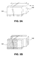
- the effective interaction length of the optical element 140 is adjusted by sliding it with respect to the mount 130. Since the strain-induced change in the retardance ⁇ ( ⁇ n ⁇ L i ) is proportional to the interaction length L i , another means, in combination with appropriate design for mount-applied strain, for adjusting both the initial total retardance (to adjust for the fabrication tolerance of the crystal length) and the slope of the retardance change with temperature (to adjust for material property variations), is provided.
- the mounting scheme is designed to avoid any non-uniformity in applied strain field at the peripheral parts of the portion of the optic that are in direct contact with the mount.
- the mount in addition to actively moving the optical element 140 relative to the entire mount as shown in Fig. 5a in order to change the interaction length, the mount could be constructed from two or more metals as shown in Fig. 5b. Motion of the optic relative to the mount in the direction of light propagation then varies the relative areas of contact with the various metals and hence varies the applied strain.
- the bimetallic mount shown in Fig. 5b is not limited to the embodiment shown in Fig. 5, but is a useful alternative to the mount described above for any embodiment where a weighted average of the strain provided by two or more different metals is required.
- the strain-stabilized BCI in accordance with the instant invention has fewer optical parts, thus reducing materials cost, assembly time, and optical insertion loss, while increasing reliability.
- Greatly reduced complexity of construction is provided by eliminating the need to measure a pool of each of two crystal types and pick appropriate crystals plus a quartz plate to achieve the desired FSR and resonant frequency.
- the instant invention provides a method of setting the resonant frequency (the facility to continuously adjust and then fix the applied 'pre-load' strain at the nominal operating temperature) that is both more accurate and precise in comparison to the discrete tuning provided by a finite set of quartz plates. Also, the instant apparatus and method removes any error in the FSR caused by mounting, since the adjustment is made on the mounted crystal.
- the -instant invention provides a more accurate control of the temperature-dependence of the BCI. Since the temperature compensation in the invention is controlled by the relative thermal expansions of the optical element and its mount, the limitation on stability is set by the repeatability of these expansions. Since the composition of crystal, glass, and metal materials is substantially repeatable, the thermal stability of the system is accurately controlled. In contrast, the thermal stability of the two-crystal BCI is set by length fabrication tolerances that are at the edge of the state-of-the-art.
- tensile strain may be more appropriate for very thin compensating plates (e.g. a thin plastic sheet).
- the instant invention disclosed herein includes a method of modifying the temperature dependence of a BCI by inducing strain in a crystal or an isotropic material that then becomes weakly birefringent under the strain.
- these concepts are combinable with any other temperature stabilization or resonant-frequency tuning technique.
- the strain is induced by applying a stress in a direction traversing the propagation of light, however, other directions are possible.
- stress refers to a force exerted when one body, or a part of one, presses upon, pulls upon, pushes against, or tends to stress, compress, or twist another body or part of one.
- the straining means includes any apparatus capable of asserting a stress on one of the crystal 110 and the glass block 120.
- active straining means such as a device using piezo-electric transducers to apply stress to the optical element 140 is possible.
- nonlinearity may be used to create some desired variation of the BCI FSR with temperature.
- nonlinear variations of the physical parameters e.g. elastooptic coefficient, thermal expansion, or compliance
- the straining means are passive and the optical system including the temperature-stabilized crystal is absent any external feedback circuits.
- the passive straining means provides a substantially constant net retardance of the light transmissive element(s) (e.g., the birefringent crystal or the combination of the birefringent crystal and the glass block) over a given temperature range and in the spectral region of desired device operation.
Landscapes
- Physics & Mathematics (AREA)
- General Physics & Mathematics (AREA)
- Optics & Photonics (AREA)
- Polarising Elements (AREA)
- Optical Modulation, Optical Deflection, Nonlinear Optics, Optical Demodulation, Optical Logic Elements (AREA)
- Crystals, And After-Treatments Of Crystals (AREA)
- Spectrometry And Color Measurement (AREA)
Abstract
Description
Claims (10)
- An optical system comprising:a first block of light transmissive birefringent material having an input port and an output port, the material having a first retardance at a first temperature; andstraining means for inducing a strain in one of the first block and a second block of light transmissive material optically coupled to the first block, the strain induced for maintaining a second net retardance substantially unchanged from the first retardance at at least a second other temperature.
- The optical system as defined in claim 1, wherein the straining means is passive.
- The optical system as defined in claim 2, wherein the straining means includes an element in contact with one of the first and second blocks, the element having a thermal expansion different than the block it is physically contacting.
- The optical system as defined in claim 3, wherein the straining means and the block it is in contact with are relatively movable for changing the interaction length Li.
- The optical system as defined in claim 4, wherein the element is a mount for supporting the block it is in contact with on three sides.
- The optical system as defined in claim 5, further including a compliant layer between the mount and the block it is in contact with for providing uniform strain.
- The optical system as defined in claim 1, wherein the second block of light transmissive material is isotropic.
- The optical system as defined in claim 1, wherein at least one of the first and second blocks of light transmissive materials has at least two substantially flat opposing sides and wherein the straining means includes a mount in close contact with the at least two opposing sides for inducing a compressive strain in the at least one of the first and second blocks of light transmissive materials.
- A method for compensating a thermal drift of a birefringent material comprising the steps of:providing a first block of light transmissive birefringent material having a first retardance at a first temperature; andmaintaining a net retardance substantially equal to the first retardance at a second temperature by applying a stress to one of the first block of light transmissive birefringent material and a second block of light transmissive material.
- A method for compensating a thermal drift of a birefringent material comprising the steps of:providing a light transmissive element having a net retardance at a first temperature, the light transmissive element comprising a block of the birefringent material; andmaintaining the net retardance of the light transmissive element at a second other temperature by inducing a strain in at least part of the light transmissive element.
Applications Claiming Priority (4)
| Application Number | Priority Date | Filing Date | Title |
|---|---|---|---|
| US23844000P | 2000-10-10 | 2000-10-10 | |
| US238440P | 2000-10-10 | ||
| US727439 | 2000-12-04 | ||
| US09/727,439 US6437916B1 (en) | 2000-10-10 | 2000-12-04 | Strain-stabilized birefringent crystal |
Publications (2)
| Publication Number | Publication Date |
|---|---|
| EP1197764A2 true EP1197764A2 (en) | 2002-04-17 |
| EP1197764A3 EP1197764A3 (en) | 2003-11-26 |
Family
ID=26931675
Family Applications (1)
| Application Number | Title | Priority Date | Filing Date |
|---|---|---|---|
| EP01308582A Withdrawn EP1197764A3 (en) | 2000-10-10 | 2001-10-08 | Strain-stabilized birefringent crystal |
Country Status (4)
| Country | Link |
|---|---|
| US (1) | US6437916B1 (en) |
| EP (1) | EP1197764A3 (en) |
| CN (1) | CN1369720A (en) |
| CA (1) | CA2358299A1 (en) |
Cited By (1)
| Publication number | Priority date | Publication date | Assignee | Title |
|---|---|---|---|---|
| WO2007046929A1 (en) * | 2005-10-20 | 2007-04-26 | Hewlett-Packard Development Company, L.P. | Light source module having harmonic generating crystal |
Families Citing this family (16)
| Publication number | Priority date | Publication date | Assignee | Title |
|---|---|---|---|---|
| US6278549B1 (en) * | 2000-04-17 | 2001-08-21 | Ciena Corporation | Optical filter having a quartz substrate |
| US7106508B2 (en) * | 2001-06-11 | 2006-09-12 | Finisar Corporation | Hybrid cell |
| CN1394026A (en) * | 2001-07-02 | 2003-01-29 | 福建华科光电有限公司 | Interleave temp compensating method |
| US8891184B2 (en) * | 2003-05-21 | 2014-11-18 | Techelan, Llc | Method and apparatus for optically-enhanced cooling |
| GB0401053D0 (en) * | 2004-01-17 | 2004-02-18 | Qinetiq Ltd | Improvements in and relating to accelerometers |
| DE102006021334B3 (en) * | 2006-05-05 | 2007-08-30 | Carl Zeiss Smt Ag | Polarization-influencing optical elements manufacturing method, involves assembling two components, and non-plane surface of component is provided with defined elevator profile is assembled to plane surface of other component |
| JP2010512544A (en) * | 2006-12-08 | 2010-04-22 | ザ・シティ・ユニヴァーシティ・オブ・ニュー・ヨーク・テクノロジー・コマーシャリゼーション・オフィス | Apparatus and method for light control in material composites |
| US20110019189A1 (en) * | 2008-08-06 | 2011-01-27 | Research Foundation Of The City University Of New York | Sub-wavelength structures, devices and methods for light control in material composites |
| US7793543B2 (en) * | 2007-05-04 | 2010-09-14 | Baker Hughes Incorporated | Method of measuring borehole gravitational acceleration |
| US8358414B2 (en) * | 2007-07-11 | 2013-01-22 | Baker Hughes Incorporated | Downhole sensors using manufactured anisotropic permittivity |
| US7751044B2 (en) * | 2007-07-11 | 2010-07-06 | Baker Hughes Incorporated | Optical sensors for downhole measurements using birefringent materials |
| US8692183B2 (en) | 2011-03-07 | 2014-04-08 | Baker Hughes Incorporated | Method and apparatus for estimating a downhole fluid property using a miniature integrated circuit spectrometer |
| TWI483052B (en) * | 2013-01-11 | 2015-05-01 | Univ Nat Central | Wavelength modulation heterodyne light source |
| CN103292688A (en) * | 2013-05-22 | 2013-09-11 | 中北大学 | Cross-symmetric-structure photoelastic-modulation interferometer with large optical path difference |
| CN104090446A (en) * | 2014-06-27 | 2014-10-08 | 哈尔滨工业大学深圳研究生院 | Method for influencing crystal light refraction index through stress compensation temperature |
| CN119437434B (en) * | 2024-11-07 | 2025-07-18 | 成都信息工程大学 | A birefringent crystal wind imaging interferometer to eliminate temperature difference |
Family Cites Families (25)
| Publication number | Priority date | Publication date | Assignee | Title |
|---|---|---|---|---|
| US3439974A (en) * | 1966-03-11 | 1969-04-22 | Bell Telephone Labor Inc | Tunable light filter |
| FR2581190B1 (en) * | 1985-04-25 | 1987-06-19 | Elf France | INTERFEROMETRIC GAS DETECTOR |
| US4890922A (en) | 1987-02-20 | 1990-01-02 | Litton Systems, Inc. | Thermally compensated reference interferometer and method |
| US4745591A (en) | 1987-02-24 | 1988-05-17 | Gte Laboratories Incorporated | Multiple channel wavelength division multiplexer/demultiplexer |
| US4744075A (en) | 1987-04-02 | 1988-05-10 | Gte Laboratories Incorporated | Multichannel wavelength multiplexer/demultiplexer |
| JPH01158326A (en) * | 1987-09-11 | 1989-06-21 | Toshiba Corp | Temperature measuring apparatus |
| US5040896A (en) | 1989-07-24 | 1991-08-20 | Behzad Moslehi | Three-crystal temperature-compensated reference interferometer for source wavelength stabilization |
| GB8921370D0 (en) | 1989-09-21 | 1989-11-08 | Smiths Industries Plc | Accelerometers |
| US5315433A (en) * | 1991-02-28 | 1994-05-24 | Fuji Photo Film Co., Ltd. | Optical wavelength converting apparatus |
| USH1155H (en) | 1991-05-10 | 1993-03-02 | American Telephone And Telegraph Company | Optical isolator with improved stabiity |
| US5175787A (en) | 1991-05-28 | 1992-12-29 | Allied-Signal Inc. | Birefringent optical waveguides of aluminum garnet |
| JPH0792325A (en) * | 1993-07-29 | 1995-04-07 | Sumitomo Electric Ind Ltd | Polarization selection element, light source module and optical fiber gyro |
| US5615224A (en) * | 1995-01-04 | 1997-03-25 | The Regents Of The University Of California | Apparatus and method for stabilization of the bandgap and associated properties of semiconductor electronic and optoelectronic devices |
| US5561522A (en) | 1995-03-27 | 1996-10-01 | Alliedsignal Inc. | Integrated birefringent-biased pressure and temperature sensor system |
| JP3660402B2 (en) * | 1995-08-23 | 2005-06-15 | 富士通株式会社 | Optical filter |
| JP3294986B2 (en) * | 1996-03-22 | 2002-06-24 | 富士通株式会社 | Optical element without temperature dependence |
| DE19637563A1 (en) * | 1996-09-14 | 1998-03-19 | Zeiss Carl Fa | Birefringent faceplate arrangement and DUV quarter-wave plate |
| US5912457A (en) * | 1996-12-30 | 1999-06-15 | The United States Of America As Represented By The Secretary Of The Army | Optically-based pressure sensor having temperature compensation |
| US5886810A (en) * | 1997-09-29 | 1999-03-23 | Hinds Instruments, Inc. | Mounting apparatus for an optical assembly of a photoelastic modulator |
| US6269202B1 (en) * | 1997-10-10 | 2001-07-31 | Dicon Fiberoptics, Inc. | Highly temperature stable filter for fiberoptic applications and system for altering the wavelength or other characteristics of optical devices |
| US6081641A (en) * | 1997-11-03 | 2000-06-27 | Applied Fiber Optics, Inc. | Thermal compensated fused-fiber dense wavelength division multiplexer |
| DE19810089A1 (en) * | 1998-03-10 | 1999-09-16 | Zeiss Carl Fa | Birefringent plate arrangement with stress birefringence |
| AU3088199A (en) * | 1998-03-16 | 1999-10-11 | Hinds Instruments, Inc. | Controlling resonant photoelastic modulators |
| US6252716B1 (en) * | 1999-07-22 | 2001-06-26 | Jds Uniphase Photonics C.V. | Bulk optic interleaver |
| US6304383B1 (en) * | 1999-09-17 | 2001-10-16 | Corning Incorporated | Controlled stress thermal compensation for filters |
-
2000
- 2000-12-04 US US09/727,439 patent/US6437916B1/en not_active Expired - Fee Related
-
2001
- 2001-10-04 CA CA002358299A patent/CA2358299A1/en not_active Abandoned
- 2001-10-08 EP EP01308582A patent/EP1197764A3/en not_active Withdrawn
- 2001-10-10 CN CN01135451.8A patent/CN1369720A/en active Pending
Cited By (1)
| Publication number | Priority date | Publication date | Assignee | Title |
|---|---|---|---|---|
| WO2007046929A1 (en) * | 2005-10-20 | 2007-04-26 | Hewlett-Packard Development Company, L.P. | Light source module having harmonic generating crystal |
Also Published As
| Publication number | Publication date |
|---|---|
| EP1197764A3 (en) | 2003-11-26 |
| CA2358299A1 (en) | 2002-04-10 |
| US6437916B1 (en) | 2002-08-20 |
| US20020080490A1 (en) | 2002-06-27 |
| CN1369720A (en) | 2002-09-18 |
Similar Documents
| Publication | Publication Date | Title |
|---|---|---|
| US6437916B1 (en) | Strain-stabilized birefringent crystal | |
| Winnie et al. | Athermal high-index-contrast waveguide design | |
| CN106526751B (en) | A kind of temperature control turnable fiber filter and preparation method thereof based on micro-nano fiber | |
| US6486999B1 (en) | Using crystalline materials to control the thermo-optic behavior of an optical path | |
| JP2001281476A (en) | Waveguide grating device and method of adjusting reflection center wavelength of waveguide grating | |
| Sakurai et al. | Control of group delay and chromatic dispersion in tunable hollow waveguide with highly reflective mirrors | |
| JPS60222805A (en) | Stable fiber optic polarizer | |
| Heimala et al. | Thermally tunable integrated optical ring resonator with poly-Si thermistor | |
| US6240225B1 (en) | Temperature compensated fiber grating and method for compensating temperature variation in fiber grating | |
| EP1498752A1 (en) | Temperature-compensated fiber grating packaging arrangement | |
| US6784416B2 (en) | Polarization transformer and polarization mode dispersion compensator | |
| US20040105485A1 (en) | Temperature compensation for acousto-optc devices | |
| Saito et al. | 100GHz-32ch athermal AWG with extremely low temperature dependency of center wavelength | |
| WO2001035133A1 (en) | Compact athermal optical waveguide using thermal expansion amplification | |
| JPH0949996A (en) | Waveguide type optical device | |
| Offrein et al. | Polarization-independent thermooptic phase shifters in silicon-oxynitride waveguides | |
| Huang et al. | Analytical solutions to estimate the stress induced polarization shift and the temperature sensitivity of optical waveguides | |
| US6721100B2 (en) | Sandwiched thin film optical filter | |
| KR100400890B1 (en) | Variable optical attenuator of in-line type and fabrication method thereof | |
| KR20180095756A (en) | Temperature-stabilized wavelength tunable optical filter | |
| You et al. | Athermal Tantalum Pentoxide Mach-Zehnder Interferometers Based on Structural Compensation Method | |
| US6427036B1 (en) | Fiber optic interferometer based switch | |
| EP1315007A1 (en) | Polarisation dependence compensation | |
| JP2001033628A (en) | Device for stabilizing and synchronizing wavelength of bragg grating | |
| JPS6316204A (en) | Mach-zehnder optical interferometer |
Legal Events
| Date | Code | Title | Description |
|---|---|---|---|
| PUAI | Public reference made under article 153(3) epc to a published international application that has entered the european phase |
Free format text: ORIGINAL CODE: 0009012 |
|
| AK | Designated contracting states |
Kind code of ref document: A2 Designated state(s): AT BE CH CY DE DK ES FI FR GB GR IE IT LI LU MC NL PT SE TR |
|
| AX | Request for extension of the european patent |
Free format text: AL;LT;LV;MK;RO;SI |
|
| PUAL | Search report despatched |
Free format text: ORIGINAL CODE: 0009013 |
|
| AK | Designated contracting states |
Kind code of ref document: A3 Designated state(s): AT BE CH CY DE DK ES FI FR GB GR IE IT LI LU MC NL PT SE TR |
|
| AX | Request for extension of the european patent |
Extension state: AL LT LV MK RO SI |
|
| AKX | Designation fees paid | ||
| REG | Reference to a national code |
Ref country code: DE Ref legal event code: 8566 |
|
| STAA | Information on the status of an ep patent application or granted ep patent |
Free format text: STATUS: THE APPLICATION IS DEEMED TO BE WITHDRAWN |
|
| 18D | Application deemed to be withdrawn |
Effective date: 20031101 |