EP1197757A2 - Inverter - Google Patents
Inverter Download PDFInfo
- Publication number
- EP1197757A2 EP1197757A2 EP01308620A EP01308620A EP1197757A2 EP 1197757 A2 EP1197757 A2 EP 1197757A2 EP 01308620 A EP01308620 A EP 01308620A EP 01308620 A EP01308620 A EP 01308620A EP 1197757 A2 EP1197757 A2 EP 1197757A2
- Authority
- EP
- European Patent Office
- Prior art keywords
- switches
- voltage
- phase
- current
- inverter
- Prior art date
- Legal status (The legal status is an assumption and is not a legal conclusion. Google has not performed a legal analysis and makes no representation as to the accuracy of the status listed.)
- Withdrawn
Links
Images


Classifications
-
- G—PHYSICS
- G01—MEASURING; TESTING
- G01R—MEASURING ELECTRIC VARIABLES; MEASURING MAGNETIC VARIABLES
- G01R19/00—Arrangements for measuring currents or voltages or for indicating presence or sign thereof
- G01R19/14—Indicating direction of current; Indicating polarity of voltage
Definitions
- the present invention relates to an inverter.
- Such inverters are used for example in the control of electric motors.
- the inverter In a conventional three phase pulse width modulator inverter controlling a load such as an asynchronous motor, the inverter has three pairs of switches connected in parallel across the power supply, with the switches of each pair connected in series, and the connection points of the switches being the points from which the output currents of the respective phases are obtained and fed to the motor.
- the switch is normally in the form of an IGBT, with a diode (freewheeling diode) connected across the IGBTs.
- inverter it is desirable to determine the motor load and it is known to determine this from the power factor between the motor voltage and the current. It is usually assumed that higher harmonics of the power factor can be neglected, and thus the power factor is usually expressed as cos ⁇ where ⁇ is the phase angle between the voltage and the current.
- the most common way to determine cos ⁇ is to measure the voltage and current independently, and to determine the time delay between the zero crossing of the two signals. From that time delay cos ⁇ can be calculated. The technique can be applied to any of the three phase current signals. It is also possible to determine cos ⁇ by measuring the current through one of the switches of each phase.
- the present invention is based on the realisation that it is possible to make use of the dead time to derive the polarity of the current, which enables cos ⁇ to be determined without using a current sensor.
- the present invention proposes that the phase voltage is determined during the dead time, and is used to determine the polarity of the phase current.
- a change in polarity of the phase current then defines the time at which the zero crossing of that current takes place. The times of the zero crossings can be used to determine the phase angle, and hence cos ⁇ .
- the present invention may be applied to any of the phases of the inverter.
- the present invention permits the polarity of phase current to be determined, and this enables a phase-related value such as cos ⁇ to be determined therefrom.
- a phase-related value such as cos ⁇
- the present invention makes use of the fact that a current is generated through one or other of the freewheeling diodes, due to inductive effects during the dead time.
- the inverter will be connected to a load such as a motor, which is at least partially inductive, but even when the load driven by the inverter is not itself inductive, the present invention may still be used by providing an appropriate inductive element.
- the determination of whether the voltage has a high or low value is at the end of the dead time, e.g. by determining it at the positive-going flank of the signal which is at a high value when either switch is on, and is at a low value when both switches are off.
- other timing arrangement may be used as long as the voltage is detected during the dead time.
- the inverter has three pairs of switches formed by transistors 10, 11; 20, 21, 30, 31 connected in parallel across a power supply U DC , with the two transistors of each pair connected in series. Freewheeling diodes 12, 22, 32 are connected across each transistor. The connection points 13, 23, 33 of each pair of transistors then form the output terminals of the inverter and are then connected to a motor 40 which is to be driven by the inverter. A capacitor 41 is also connected in parallel across the power supply U DC .
- Each of the transistors 10, 11; 20, 21; 30, 31 has its gate terminal connected to a processor 50.
- the processor 50 is connected to the transistors 10, 11 via gate drive units 14 which control the switching of transistors 10, 11.
- the processor 50 generates pulse width modulation pulses which are amplified and level shifted by the gate drive units 14 whilst theoretically the switching on of transistor 10 should be simultaneous with the switching off of transistor 11, and vice versa, the need to avoid them both being on simultaneously results in there being a dead time when both are off.
- the freewheeling diodes 12 in parallel to the transistors 10, 11 make it possible for the current to freewheel through the (partly) inductive load.
- the polarity of the phase current may be determined.
- a change in polarity defines the time at which a zero crossing of the current takes place.
- the signals from the processor 50 to the gate drive units 14 are illustrated in Fig. 2.
- the signal to the transistor 10 is illustrated by line 60, and the signal to transistor 11 by line 61.
- the signals to the respective gate drive units 14 are also passed to an OR gate 51 which derives a dead time signal shown by line 62 in Fig. 2. That dead time signal corresponding to line 62 is passed from OR gate 51 to the clock input Cl of a latch 52.
- connection 53 the voltage at the connection point 13 between transistors 10 and 11 is passed via connection 53 to a comparator 54 which generates a signal which is either high or low dependant on whether the voltage on connection 53 is higher or lower than a reference voltage V ref .
- the signal generated by the comparator 54 is input to the latch 52.
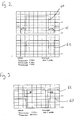
- Fig. 3 then illustrates the relationship between the dead time signal 53 input to the latch 52 from gate 51 and the voltage on connection 53.
- the time scale of Fig. 3 is slightly different from that of Fig. 2, and also that the signal 63 corresponding to line 63 in Fig. 2, being the signal on connection 53, may change its relative position.
- the signal corresponding to line 63 is low at the start of both positive-going flanks 64 of the signal corresponding to line 62.
- the voltage on connection 53 corresponding to line 63 in Fig. 3
- this is due to the fact that the diode 12 across transistor 11 is conducting, and it is therefore known that the output current is positive.
- Fig. 4 then illustrates the effect of this, on a longer time scale than in Fig. 3.
- the upper two graphs correspond to Fig. 3 over a long time period. During that time period, there will be times when the relationship between lines 62 and 63 is identical to that in Fig. 3, and sometimes when the line 63 is non-zero at the positive-going flank 64 of line 62.
- the latch 52 determines this relationship by comparing its inputs and generates an output on line 55 corresponding to line 65 in Fig. 4. This gives the sign of the motor current, and switches between two levels such as zero volts and a positive value, as the output current changes sign. In practice, due to ripple on the output current, there will be several transitions around the time at which the motor current changes sign, as illustrated by line 65 in Fig. 4 and some signal conditioning may be necessary to determine the zero crossings used. This introduces at worst only a small error to the determination of the phase angle ⁇ . Line 65 in Fig. 4 also illustrates that there is noise which causes small variations in the measured values but again this does not affect the operation of the present invention as long as the level is detected correctly.
- the signal output from the latch 52 on connection 55 corresponding to line 65 in Fig. 4 is then passed to the processor 50, which is also generating the pulse width modulated sinusoidal voltage.
- the phase shift between the zero crossing points of the voltage (determined by the signals to the gate drive units 14) and the zero crossings of the motor current derived from the line 65 on connection 55 is then the angle ⁇ from which cos ⁇ can be determined.
- the present invention permits cos ⁇ to be determined without measuring the current itself, but instead relying on the detection of the zero crossings of that current within the dead time periods.
- the present invention is not limited to the example described and, for example, the operations described could be applied to transistors 20, 21 or the transistors 30, 31.
- the embodiment has been described in terms of hardware, including the OR gate 51, latch 52 and comparator 54, it is possible for those components to be embodied wholly or partially as software in a suitable processing device.
- the signal on connection 53 may need to be converted from anolog to digital embodiment.
- the present invention determines cos ⁇ of the output of the inverter, which is not necessarily equal to cos ⁇ of the motor 40 driven by the inverter.
- the invention limited to the use of an inverter driving a motor. Normally, the invention will be applied where the inverter is connected to a (partially) inductive load, although the invention could be applied to other loads if an inductive element it included which causes current to be generated through the freewheeling diodes.
- the inverter may have any number of phases, and any number of switches in series. The switches themselves need not be transistors as described in the embodiment above.
- the embodiment describes the determination of cos ⁇ , since that term is normally used to express the power factor, it will appreciated by those in the art that the power factor may be expressed in any term which relates to the relative phase position of the voltage and current, or the time delay between the voltage and current, such as sin ⁇ or tan ⁇ and the invention may therefore be used to determined such quantities accordingly.
Landscapes
- Physics & Mathematics (AREA)
- General Physics & Mathematics (AREA)
- Inverter Devices (AREA)
Abstract
Description
Claims (5)
- A method of determining the polarity of the current of a phase of an inverter having at least two switches, with the switches being connected in series and respective freewheeling diodes being connected in parallel with the switches
the method comprising:switching the switches on and off alternately, the switching being such that there is a predetermined duration between each switching during which the switches are both off;detecting the phase voltage at the connection of the switches;determining if said voltage has a high or low value during each said predetermined duration and generating a signal which has a first value when said voltage has a high value during of any one of said predetermined durations and has a second value when said voltage has a low value during of any one of said predetermined durations; anddetermining the times of transitions between said first and second values, thereby to determining the polarity of the phase current corresponding to said phase voltage. - A method according to claim 1, wherein the determining of said voltage has a high or low value is at the end of each said predetermined duration.
- A method according to claim 1 or claim 2, wherein the times of said transitions are compared with the times of switching of said switches, so as to derive the phase relationship therebetween.
- A apparatus for determining the polarity of the current of a phase of an inverter, the inverter having at least two switches, with the switches being connected in series and respective freewheeling diodes being connected in parallel with the switches, the apparatus comprising:means for switching the switches on and off alternately, the switching being such that there is a predetermined duration between each switching during which the switches are both off;means for detecting the phase voltage at the connection of the switches;means for determining if said voltage has a high or low value during each said predetermined duration and generating a signal which has a first value when said voltage has a high value during of any one of said predetermined durations and has a second value when said voltage has a low value during of any one of said predetermined durations; andmeans for determining the times of transitions between said first and second values, thereby to determining the polarity of the phase current corresponding to said phase voltage.
- An apparatus according to claim 4, further comprising means for comparing the times of said transistors with the times of switching of said switches, so as to derive the phase relationship therebetween.
Applications Claiming Priority (2)
| Application Number | Priority Date | Filing Date | Title |
|---|---|---|---|
| GB0024847 | 2000-10-10 | ||
| GB0024847A GB0024847D0 (en) | 2000-10-10 | 2000-10-10 | Inverter |
Publications (2)
| Publication Number | Publication Date |
|---|---|
| EP1197757A2 true EP1197757A2 (en) | 2002-04-17 |
| EP1197757A3 EP1197757A3 (en) | 2003-10-01 |
Family
ID=9901036
Family Applications (1)
| Application Number | Title | Priority Date | Filing Date |
|---|---|---|---|
| EP01308620A Withdrawn EP1197757A3 (en) | 2000-10-10 | 2001-10-09 | Inverter |
Country Status (2)
| Country | Link |
|---|---|
| EP (1) | EP1197757A3 (en) |
| GB (1) | GB0024847D0 (en) |
Cited By (1)
| Publication number | Priority date | Publication date | Assignee | Title |
|---|---|---|---|---|
| US11159098B2 (en) | 2019-04-05 | 2021-10-26 | Infineon Technologies Ag | Method and half bridge controller for determining a polarity of a half bridge current |
Family Cites Families (2)
| Publication number | Priority date | Publication date | Assignee | Title |
|---|---|---|---|---|
| US5627447A (en) * | 1995-09-29 | 1997-05-06 | Allen-Bradley Company, Inc. | Method and apparatus for detecting current delay angle from motor terminal voltage |
| JPH11183531A (en) * | 1997-12-17 | 1999-07-09 | Yaskawa Electric Corp | Inverter output current polarity detection method |
-
2000
- 2000-10-10 GB GB0024847A patent/GB0024847D0/en not_active Ceased
-
2001
- 2001-10-09 EP EP01308620A patent/EP1197757A3/en not_active Withdrawn
Cited By (1)
| Publication number | Priority date | Publication date | Assignee | Title |
|---|---|---|---|---|
| US11159098B2 (en) | 2019-04-05 | 2021-10-26 | Infineon Technologies Ag | Method and half bridge controller for determining a polarity of a half bridge current |
Also Published As
| Publication number | Publication date |
|---|---|
| GB0024847D0 (en) | 2000-11-22 |
| EP1197757A3 (en) | 2003-10-01 |
Similar Documents
| Publication | Publication Date | Title |
|---|---|---|
| CN110323991B (en) | Power module and method for providing multiphase current to multiphase load | |
| CN101494431B (en) | Controller of multi-phase electric motor | |
| US7049778B2 (en) | Inverter control apparatus and inverter control method | |
| CN102067432B (en) | Printed circuit boards, methods for determining the space vector of currents, converters, printed circuit boards and converter structures series | |
| KR100416865B1 (en) | Brushless motor drive circuit having low noise and high efficiency | |
| EP0144593B1 (en) | Control system for a voltage-type inverter | |
| US20070296371A1 (en) | Position sensorless control apparatus for synchronous motor | |
| US5627447A (en) | Method and apparatus for detecting current delay angle from motor terminal voltage | |
| CN102299648B (en) | Power converter | |
| US11658600B2 (en) | Motor controller, motor system and method for controlling motor | |
| US11804797B2 (en) | Motor controller, motor system and method for controlling motor | |
| JP2009124782A (en) | Multiphase electric motor controller | |
| CN114128130A (en) | Motor control device and motor system | |
| US20190393804A1 (en) | Method of Operating an Inverter and Inverter | |
| JP7295519B2 (en) | Degradation estimating device and degradation estimating program for power converter | |
| CN114008901A (en) | Current measuring device and power conversion device | |
| CN111817594B (en) | Method for determining polarity of half-bridge current and half-bridge controller | |
| JP2009118681A (en) | Control device for multiphase motor | |
| JP2003348876A (en) | Inverter device, semiconductor integrated circuit device, and multiplier | |
| US11716045B2 (en) | Motor controller, motor system and method for controlling motor | |
| JP2009118622A (en) | Control device for multiphase motor | |
| JPH0698557A (en) | Pulse width modulation control inverter control circuit | |
| JP2003079159A (en) | Pulse width modulation type power converter | |
| KR100734467B1 (en) | Sensorless Control of Switched Reluctance Motor Using Voltage Pulse Injection Method and Its Method | |
| JP2000184732A (en) | Inverter device |
Legal Events
| Date | Code | Title | Description |
|---|---|---|---|
| PUAI | Public reference made under article 153(3) epc to a published international application that has entered the european phase |
Free format text: ORIGINAL CODE: 0009012 |
|
| AK | Designated contracting states |
Kind code of ref document: A2 Designated state(s): AT BE CH CY DE DK ES FI FR GB GR IE IT LI LU MC NL PT SE TR |
|
| AX | Request for extension of the european patent |
Free format text: AL;LT;LV;MK;RO;SI |
|
| PUAL | Search report despatched |
Free format text: ORIGINAL CODE: 0009013 |
|
| AK | Designated contracting states |
Kind code of ref document: A3 Designated state(s): AT BE CH CY DE DK ES FI FR GB GR IE IT LI LU MC NL PT SE TR |
|
| AX | Request for extension of the european patent |
Extension state: AL LT LV MK RO SI |
|
| AKX | Designation fees paid | ||
| REG | Reference to a national code |
Ref country code: DE Ref legal event code: 8566 |
|
| STAA | Information on the status of an ep patent application or granted ep patent |
Free format text: STATUS: THE APPLICATION IS DEEMED TO BE WITHDRAWN |
|
| 18D | Application deemed to be withdrawn |
Effective date: 20040402 |