EP1197448A9 - Article feeding and discharging device - Google Patents
Article feeding and discharging device Download PDFInfo
- Publication number
- EP1197448A9 EP1197448A9 EP01906357A EP01906357A EP1197448A9 EP 1197448 A9 EP1197448 A9 EP 1197448A9 EP 01906357 A EP01906357 A EP 01906357A EP 01906357 A EP01906357 A EP 01906357A EP 1197448 A9 EP1197448 A9 EP 1197448A9
- Authority
- EP
- European Patent Office
- Prior art keywords
- hold current
- current
- motor
- shutter
- materials
- Prior art date
- Legal status (The legal status is an assumption and is not a legal conclusion. Google has not performed a legal analysis and makes no representation as to the accuracy of the status listed.)
- Withdrawn
Links
- 238000007599 discharging Methods 0.000 title abstract description 8
- 239000000463 material Substances 0.000 claims abstract description 243
- 230000035939 shock Effects 0.000 claims abstract description 25
- 230000005484 gravity Effects 0.000 claims abstract description 21
- 230000003068 static effect Effects 0.000 claims description 5
- 238000005303 weighing Methods 0.000 description 78
- 238000010586 diagram Methods 0.000 description 8
- 230000002093 peripheral effect Effects 0.000 description 6
- 239000006185 dispersion Substances 0.000 description 4
- 230000005855 radiation Effects 0.000 description 4
- MIDXCONKKJTLDX-UHFFFAOYSA-N 3,5-dimethylcyclopentane-1,2-dione Chemical compound CC1CC(C)C(=O)C1=O MIDXCONKKJTLDX-UHFFFAOYSA-N 0.000 description 1
- 235000013736 caramel Nutrition 0.000 description 1
- 235000009508 confectionery Nutrition 0.000 description 1
- 230000000694 effects Effects 0.000 description 1
- 230000001939 inductive effect Effects 0.000 description 1
- 238000000034 method Methods 0.000 description 1
- 238000004806 packaging method and process Methods 0.000 description 1
- 238000012856 packing Methods 0.000 description 1
Images




Classifications
-
- C—CHEMISTRY; METALLURGY
- C04—CEMENTS; CONCRETE; ARTIFICIAL STONE; CERAMICS; REFRACTORIES
- C04B—LIME, MAGNESIA; SLAG; CEMENTS; COMPOSITIONS THEREOF, e.g. MORTARS, CONCRETE OR LIKE BUILDING MATERIALS; ARTIFICIAL STONE; CERAMICS; REFRACTORIES; TREATMENT OF NATURAL STONE
- C04B37/00—Joining burned ceramic articles with other burned ceramic articles or other articles by heating
- C04B37/02—Joining burned ceramic articles with other burned ceramic articles or other articles by heating with metallic articles
- C04B37/023—Joining burned ceramic articles with other burned ceramic articles or other articles by heating with metallic articles characterised by the interlayer used
- C04B37/026—Joining burned ceramic articles with other burned ceramic articles or other articles by heating with metallic articles characterised by the interlayer used consisting of metals or metal salts
-
- B—PERFORMING OPERATIONS; TRANSPORTING
- B32—LAYERED PRODUCTS
- B32B—LAYERED PRODUCTS, i.e. PRODUCTS BUILT-UP OF STRATA OF FLAT OR NON-FLAT, e.g. CELLULAR OR HONEYCOMB, FORM
- B32B18/00—Layered products essentially comprising ceramics, e.g. refractory products
-
- C—CHEMISTRY; METALLURGY
- C04—CEMENTS; CONCRETE; ARTIFICIAL STONE; CERAMICS; REFRACTORIES
- C04B—LIME, MAGNESIA; SLAG; CEMENTS; COMPOSITIONS THEREOF, e.g. MORTARS, CONCRETE OR LIKE BUILDING MATERIALS; ARTIFICIAL STONE; CERAMICS; REFRACTORIES; TREATMENT OF NATURAL STONE
- C04B37/00—Joining burned ceramic articles with other burned ceramic articles or other articles by heating
- C04B37/02—Joining burned ceramic articles with other burned ceramic articles or other articles by heating with metallic articles
- C04B37/021—Joining burned ceramic articles with other burned ceramic articles or other articles by heating with metallic articles in a direct manner, e.g. direct copper bonding [DCB]
-
- G—PHYSICS
- G01—MEASURING; TESTING
- G01G—WEIGHING
- G01G13/00—Weighing apparatus with automatic feed or discharge for weighing-out batches of material
- G01G13/16—Means for automatically discharging weigh receptacles under control of the weighing mechanism
- G01G13/18—Means for automatically discharging weigh receptacles under control of the weighing mechanism by valves or flaps in the container bottom
-
- H—ELECTRICITY
- H01—ELECTRIC ELEMENTS
- H01M—PROCESSES OR MEANS, e.g. BATTERIES, FOR THE DIRECT CONVERSION OF CHEMICAL ENERGY INTO ELECTRICAL ENERGY
- H01M4/00—Electrodes
- H01M4/02—Electrodes composed of, or comprising, active material
- H01M4/64—Carriers or collectors
- H01M4/66—Selection of materials
- H01M4/661—Metal or alloys, e.g. alloy coatings
-
- H—ELECTRICITY
- H01—ELECTRIC ELEMENTS
- H01M—PROCESSES OR MEANS, e.g. BATTERIES, FOR THE DIRECT CONVERSION OF CHEMICAL ENERGY INTO ELECTRICAL ENERGY
- H01M4/00—Electrodes
- H01M4/02—Electrodes composed of, or comprising, active material
- H01M4/64—Carriers or collectors
- H01M4/66—Selection of materials
- H01M4/665—Composites
- H01M4/667—Composites in the form of layers, e.g. coatings
-
- B—PERFORMING OPERATIONS; TRANSPORTING
- B32—LAYERED PRODUCTS
- B32B—LAYERED PRODUCTS, i.e. PRODUCTS BUILT-UP OF STRATA OF FLAT OR NON-FLAT, e.g. CELLULAR OR HONEYCOMB, FORM
- B32B2311/00—Metals, their alloys or their compounds
- B32B2311/02—Noble metals
- B32B2311/06—Platinum
-
- B—PERFORMING OPERATIONS; TRANSPORTING
- B32—LAYERED PRODUCTS
- B32B—LAYERED PRODUCTS, i.e. PRODUCTS BUILT-UP OF STRATA OF FLAT OR NON-FLAT, e.g. CELLULAR OR HONEYCOMB, FORM
- B32B2311/00—Metals, their alloys or their compounds
- B32B2311/02—Noble metals
- B32B2311/08—Silver
-
- B—PERFORMING OPERATIONS; TRANSPORTING
- B32—LAYERED PRODUCTS
- B32B—LAYERED PRODUCTS, i.e. PRODUCTS BUILT-UP OF STRATA OF FLAT OR NON-FLAT, e.g. CELLULAR OR HONEYCOMB, FORM
- B32B2311/00—Metals, their alloys or their compounds
- B32B2311/02—Noble metals
- B32B2311/09—Palladium
-
- B—PERFORMING OPERATIONS; TRANSPORTING
- B32—LAYERED PRODUCTS
- B32B—LAYERED PRODUCTS, i.e. PRODUCTS BUILT-UP OF STRATA OF FLAT OR NON-FLAT, e.g. CELLULAR OR HONEYCOMB, FORM
- B32B2311/00—Metals, their alloys or their compounds
- B32B2311/12—Copper
-
- B—PERFORMING OPERATIONS; TRANSPORTING
- B32—LAYERED PRODUCTS
- B32B—LAYERED PRODUCTS, i.e. PRODUCTS BUILT-UP OF STRATA OF FLAT OR NON-FLAT, e.g. CELLULAR OR HONEYCOMB, FORM
- B32B2311/00—Metals, their alloys or their compounds
- B32B2311/14—Lead
-
- B—PERFORMING OPERATIONS; TRANSPORTING
- B32—LAYERED PRODUCTS
- B32B—LAYERED PRODUCTS, i.e. PRODUCTS BUILT-UP OF STRATA OF FLAT OR NON-FLAT, e.g. CELLULAR OR HONEYCOMB, FORM
- B32B2311/00—Metals, their alloys or their compounds
- B32B2311/16—Tin
-
- B—PERFORMING OPERATIONS; TRANSPORTING
- B32—LAYERED PRODUCTS
- B32B—LAYERED PRODUCTS, i.e. PRODUCTS BUILT-UP OF STRATA OF FLAT OR NON-FLAT, e.g. CELLULAR OR HONEYCOMB, FORM
- B32B2311/00—Metals, their alloys or their compounds
- B32B2311/18—Titanium
-
- B—PERFORMING OPERATIONS; TRANSPORTING
- B32—LAYERED PRODUCTS
- B32B—LAYERED PRODUCTS, i.e. PRODUCTS BUILT-UP OF STRATA OF FLAT OR NON-FLAT, e.g. CELLULAR OR HONEYCOMB, FORM
- B32B2311/00—Metals, their alloys or their compounds
- B32B2311/20—Zinc
-
- B—PERFORMING OPERATIONS; TRANSPORTING
- B32—LAYERED PRODUCTS
- B32B—LAYERED PRODUCTS, i.e. PRODUCTS BUILT-UP OF STRATA OF FLAT OR NON-FLAT, e.g. CELLULAR OR HONEYCOMB, FORM
- B32B2311/00—Metals, their alloys or their compounds
- B32B2311/22—Nickel or cobalt
-
- B—PERFORMING OPERATIONS; TRANSPORTING
- B32—LAYERED PRODUCTS
- B32B—LAYERED PRODUCTS, i.e. PRODUCTS BUILT-UP OF STRATA OF FLAT OR NON-FLAT, e.g. CELLULAR OR HONEYCOMB, FORM
- B32B2311/00—Metals, their alloys or their compounds
- B32B2311/24—Aluminium
-
- B—PERFORMING OPERATIONS; TRANSPORTING
- B32—LAYERED PRODUCTS
- B32B—LAYERED PRODUCTS, i.e. PRODUCTS BUILT-UP OF STRATA OF FLAT OR NON-FLAT, e.g. CELLULAR OR HONEYCOMB, FORM
- B32B2311/00—Metals, their alloys or their compounds
- B32B2311/30—Iron, e.g. steel
-
- C—CHEMISTRY; METALLURGY
- C04—CEMENTS; CONCRETE; ARTIFICIAL STONE; CERAMICS; REFRACTORIES
- C04B—LIME, MAGNESIA; SLAG; CEMENTS; COMPOSITIONS THEREOF, e.g. MORTARS, CONCRETE OR LIKE BUILDING MATERIALS; ARTIFICIAL STONE; CERAMICS; REFRACTORIES; TREATMENT OF NATURAL STONE
- C04B2235/00—Aspects relating to ceramic starting mixtures or sintered ceramic products
- C04B2235/65—Aspects relating to heat treatments of ceramic bodies such as green ceramics or pre-sintered ceramics, e.g. burning, sintering or melting processes
- C04B2235/658—Atmosphere during thermal treatment
-
- C—CHEMISTRY; METALLURGY
- C04—CEMENTS; CONCRETE; ARTIFICIAL STONE; CERAMICS; REFRACTORIES
- C04B—LIME, MAGNESIA; SLAG; CEMENTS; COMPOSITIONS THEREOF, e.g. MORTARS, CONCRETE OR LIKE BUILDING MATERIALS; ARTIFICIAL STONE; CERAMICS; REFRACTORIES; TREATMENT OF NATURAL STONE
- C04B2235/00—Aspects relating to ceramic starting mixtures or sintered ceramic products
- C04B2235/65—Aspects relating to heat treatments of ceramic bodies such as green ceramics or pre-sintered ceramics, e.g. burning, sintering or melting processes
- C04B2235/66—Specific sintering techniques, e.g. centrifugal sintering
- C04B2235/667—Sintering using wave energy, e.g. microwave sintering
-
- C—CHEMISTRY; METALLURGY
- C04—CEMENTS; CONCRETE; ARTIFICIAL STONE; CERAMICS; REFRACTORIES
- C04B—LIME, MAGNESIA; SLAG; CEMENTS; COMPOSITIONS THEREOF, e.g. MORTARS, CONCRETE OR LIKE BUILDING MATERIALS; ARTIFICIAL STONE; CERAMICS; REFRACTORIES; TREATMENT OF NATURAL STONE
- C04B2237/00—Aspects relating to ceramic laminates or to joining of ceramic articles with other articles by heating
- C04B2237/02—Aspects relating to interlayers, e.g. used to join ceramic articles with other articles by heating
- C04B2237/04—Ceramic interlayers
- C04B2237/08—Non-oxidic interlayers
- C04B2237/086—Carbon interlayers
-
- C—CHEMISTRY; METALLURGY
- C04—CEMENTS; CONCRETE; ARTIFICIAL STONE; CERAMICS; REFRACTORIES
- C04B—LIME, MAGNESIA; SLAG; CEMENTS; COMPOSITIONS THEREOF, e.g. MORTARS, CONCRETE OR LIKE BUILDING MATERIALS; ARTIFICIAL STONE; CERAMICS; REFRACTORIES; TREATMENT OF NATURAL STONE
- C04B2237/00—Aspects relating to ceramic laminates or to joining of ceramic articles with other articles by heating
- C04B2237/02—Aspects relating to interlayers, e.g. used to join ceramic articles with other articles by heating
- C04B2237/12—Metallic interlayers
- C04B2237/122—Metallic interlayers based on refractory metals
-
- C—CHEMISTRY; METALLURGY
- C04—CEMENTS; CONCRETE; ARTIFICIAL STONE; CERAMICS; REFRACTORIES
- C04B—LIME, MAGNESIA; SLAG; CEMENTS; COMPOSITIONS THEREOF, e.g. MORTARS, CONCRETE OR LIKE BUILDING MATERIALS; ARTIFICIAL STONE; CERAMICS; REFRACTORIES; TREATMENT OF NATURAL STONE
- C04B2237/00—Aspects relating to ceramic laminates or to joining of ceramic articles with other articles by heating
- C04B2237/02—Aspects relating to interlayers, e.g. used to join ceramic articles with other articles by heating
- C04B2237/12—Metallic interlayers
- C04B2237/124—Metallic interlayers based on copper
-
- C—CHEMISTRY; METALLURGY
- C04—CEMENTS; CONCRETE; ARTIFICIAL STONE; CERAMICS; REFRACTORIES
- C04B—LIME, MAGNESIA; SLAG; CEMENTS; COMPOSITIONS THEREOF, e.g. MORTARS, CONCRETE OR LIKE BUILDING MATERIALS; ARTIFICIAL STONE; CERAMICS; REFRACTORIES; TREATMENT OF NATURAL STONE
- C04B2237/00—Aspects relating to ceramic laminates or to joining of ceramic articles with other articles by heating
- C04B2237/02—Aspects relating to interlayers, e.g. used to join ceramic articles with other articles by heating
- C04B2237/12—Metallic interlayers
- C04B2237/126—Metallic interlayers wherein the active component for bonding is not the largest fraction of the interlayer
- C04B2237/127—The active component for bonding being a refractory metal
-
- C—CHEMISTRY; METALLURGY
- C04—CEMENTS; CONCRETE; ARTIFICIAL STONE; CERAMICS; REFRACTORIES
- C04B—LIME, MAGNESIA; SLAG; CEMENTS; COMPOSITIONS THEREOF, e.g. MORTARS, CONCRETE OR LIKE BUILDING MATERIALS; ARTIFICIAL STONE; CERAMICS; REFRACTORIES; TREATMENT OF NATURAL STONE
- C04B2237/00—Aspects relating to ceramic laminates or to joining of ceramic articles with other articles by heating
- C04B2237/30—Composition of layers of ceramic laminates or of ceramic or metallic articles to be joined by heating, e.g. Si substrates
- C04B2237/32—Ceramic
- C04B2237/36—Non-oxidic
- C04B2237/363—Carbon
-
- C—CHEMISTRY; METALLURGY
- C04—CEMENTS; CONCRETE; ARTIFICIAL STONE; CERAMICS; REFRACTORIES
- C04B—LIME, MAGNESIA; SLAG; CEMENTS; COMPOSITIONS THEREOF, e.g. MORTARS, CONCRETE OR LIKE BUILDING MATERIALS; ARTIFICIAL STONE; CERAMICS; REFRACTORIES; TREATMENT OF NATURAL STONE
- C04B2237/00—Aspects relating to ceramic laminates or to joining of ceramic articles with other articles by heating
- C04B2237/30—Composition of layers of ceramic laminates or of ceramic or metallic articles to be joined by heating, e.g. Si substrates
- C04B2237/32—Ceramic
- C04B2237/38—Fiber or whisker reinforced
- C04B2237/385—Carbon or carbon composite
-
- C—CHEMISTRY; METALLURGY
- C04—CEMENTS; CONCRETE; ARTIFICIAL STONE; CERAMICS; REFRACTORIES
- C04B—LIME, MAGNESIA; SLAG; CEMENTS; COMPOSITIONS THEREOF, e.g. MORTARS, CONCRETE OR LIKE BUILDING MATERIALS; ARTIFICIAL STONE; CERAMICS; REFRACTORIES; TREATMENT OF NATURAL STONE
- C04B2237/00—Aspects relating to ceramic laminates or to joining of ceramic articles with other articles by heating
- C04B2237/30—Composition of layers of ceramic laminates or of ceramic or metallic articles to be joined by heating, e.g. Si substrates
- C04B2237/40—Metallic
-
- C—CHEMISTRY; METALLURGY
- C04—CEMENTS; CONCRETE; ARTIFICIAL STONE; CERAMICS; REFRACTORIES
- C04B—LIME, MAGNESIA; SLAG; CEMENTS; COMPOSITIONS THEREOF, e.g. MORTARS, CONCRETE OR LIKE BUILDING MATERIALS; ARTIFICIAL STONE; CERAMICS; REFRACTORIES; TREATMENT OF NATURAL STONE
- C04B2237/00—Aspects relating to ceramic laminates or to joining of ceramic articles with other articles by heating
- C04B2237/30—Composition of layers of ceramic laminates or of ceramic or metallic articles to be joined by heating, e.g. Si substrates
- C04B2237/40—Metallic
- C04B2237/402—Aluminium
-
- C—CHEMISTRY; METALLURGY
- C04—CEMENTS; CONCRETE; ARTIFICIAL STONE; CERAMICS; REFRACTORIES
- C04B—LIME, MAGNESIA; SLAG; CEMENTS; COMPOSITIONS THEREOF, e.g. MORTARS, CONCRETE OR LIKE BUILDING MATERIALS; ARTIFICIAL STONE; CERAMICS; REFRACTORIES; TREATMENT OF NATURAL STONE
- C04B2237/00—Aspects relating to ceramic laminates or to joining of ceramic articles with other articles by heating
- C04B2237/30—Composition of layers of ceramic laminates or of ceramic or metallic articles to be joined by heating, e.g. Si substrates
- C04B2237/40—Metallic
- C04B2237/403—Refractory metals
-
- C—CHEMISTRY; METALLURGY
- C04—CEMENTS; CONCRETE; ARTIFICIAL STONE; CERAMICS; REFRACTORIES
- C04B—LIME, MAGNESIA; SLAG; CEMENTS; COMPOSITIONS THEREOF, e.g. MORTARS, CONCRETE OR LIKE BUILDING MATERIALS; ARTIFICIAL STONE; CERAMICS; REFRACTORIES; TREATMENT OF NATURAL STONE
- C04B2237/00—Aspects relating to ceramic laminates or to joining of ceramic articles with other articles by heating
- C04B2237/30—Composition of layers of ceramic laminates or of ceramic or metallic articles to be joined by heating, e.g. Si substrates
- C04B2237/40—Metallic
- C04B2237/404—Manganese or rhenium
-
- C—CHEMISTRY; METALLURGY
- C04—CEMENTS; CONCRETE; ARTIFICIAL STONE; CERAMICS; REFRACTORIES
- C04B—LIME, MAGNESIA; SLAG; CEMENTS; COMPOSITIONS THEREOF, e.g. MORTARS, CONCRETE OR LIKE BUILDING MATERIALS; ARTIFICIAL STONE; CERAMICS; REFRACTORIES; TREATMENT OF NATURAL STONE
- C04B2237/00—Aspects relating to ceramic laminates or to joining of ceramic articles with other articles by heating
- C04B2237/30—Composition of layers of ceramic laminates or of ceramic or metallic articles to be joined by heating, e.g. Si substrates
- C04B2237/40—Metallic
- C04B2237/405—Iron metal group, e.g. Co or Ni
-
- C—CHEMISTRY; METALLURGY
- C04—CEMENTS; CONCRETE; ARTIFICIAL STONE; CERAMICS; REFRACTORIES
- C04B—LIME, MAGNESIA; SLAG; CEMENTS; COMPOSITIONS THEREOF, e.g. MORTARS, CONCRETE OR LIKE BUILDING MATERIALS; ARTIFICIAL STONE; CERAMICS; REFRACTORIES; TREATMENT OF NATURAL STONE
- C04B2237/00—Aspects relating to ceramic laminates or to joining of ceramic articles with other articles by heating
- C04B2237/30—Composition of layers of ceramic laminates or of ceramic or metallic articles to be joined by heating, e.g. Si substrates
- C04B2237/40—Metallic
- C04B2237/405—Iron metal group, e.g. Co or Ni
- C04B2237/406—Iron, e.g. steel
-
- C—CHEMISTRY; METALLURGY
- C04—CEMENTS; CONCRETE; ARTIFICIAL STONE; CERAMICS; REFRACTORIES
- C04B—LIME, MAGNESIA; SLAG; CEMENTS; COMPOSITIONS THEREOF, e.g. MORTARS, CONCRETE OR LIKE BUILDING MATERIALS; ARTIFICIAL STONE; CERAMICS; REFRACTORIES; TREATMENT OF NATURAL STONE
- C04B2237/00—Aspects relating to ceramic laminates or to joining of ceramic articles with other articles by heating
- C04B2237/30—Composition of layers of ceramic laminates or of ceramic or metallic articles to be joined by heating, e.g. Si substrates
- C04B2237/40—Metallic
- C04B2237/407—Copper
-
- C—CHEMISTRY; METALLURGY
- C04—CEMENTS; CONCRETE; ARTIFICIAL STONE; CERAMICS; REFRACTORIES
- C04B—LIME, MAGNESIA; SLAG; CEMENTS; COMPOSITIONS THEREOF, e.g. MORTARS, CONCRETE OR LIKE BUILDING MATERIALS; ARTIFICIAL STONE; CERAMICS; REFRACTORIES; TREATMENT OF NATURAL STONE
- C04B2237/00—Aspects relating to ceramic laminates or to joining of ceramic articles with other articles by heating
- C04B2237/30—Composition of layers of ceramic laminates or of ceramic or metallic articles to be joined by heating, e.g. Si substrates
- C04B2237/40—Metallic
- C04B2237/408—Noble metals, e.g. palladium, platina or silver
-
- C—CHEMISTRY; METALLURGY
- C04—CEMENTS; CONCRETE; ARTIFICIAL STONE; CERAMICS; REFRACTORIES
- C04B—LIME, MAGNESIA; SLAG; CEMENTS; COMPOSITIONS THEREOF, e.g. MORTARS, CONCRETE OR LIKE BUILDING MATERIALS; ARTIFICIAL STONE; CERAMICS; REFRACTORIES; TREATMENT OF NATURAL STONE
- C04B2237/00—Aspects relating to ceramic laminates or to joining of ceramic articles with other articles by heating
- C04B2237/50—Processing aspects relating to ceramic laminates or to the joining of ceramic articles with other articles by heating
- C04B2237/52—Pre-treatment of the joining surfaces, e.g. cleaning, machining
-
- C—CHEMISTRY; METALLURGY
- C04—CEMENTS; CONCRETE; ARTIFICIAL STONE; CERAMICS; REFRACTORIES
- C04B—LIME, MAGNESIA; SLAG; CEMENTS; COMPOSITIONS THEREOF, e.g. MORTARS, CONCRETE OR LIKE BUILDING MATERIALS; ARTIFICIAL STONE; CERAMICS; REFRACTORIES; TREATMENT OF NATURAL STONE
- C04B2237/00—Aspects relating to ceramic laminates or to joining of ceramic articles with other articles by heating
- C04B2237/50—Processing aspects relating to ceramic laminates or to the joining of ceramic articles with other articles by heating
- C04B2237/60—Forming at the joining interface or in the joining layer specific reaction phases or zones, e.g. diffusion of reactive species from the interlayer to the substrate or from a substrate to the joining interface, carbide forming at the joining interface
-
- C—CHEMISTRY; METALLURGY
- C04—CEMENTS; CONCRETE; ARTIFICIAL STONE; CERAMICS; REFRACTORIES
- C04B—LIME, MAGNESIA; SLAG; CEMENTS; COMPOSITIONS THEREOF, e.g. MORTARS, CONCRETE OR LIKE BUILDING MATERIALS; ARTIFICIAL STONE; CERAMICS; REFRACTORIES; TREATMENT OF NATURAL STONE
- C04B2237/00—Aspects relating to ceramic laminates or to joining of ceramic articles with other articles by heating
- C04B2237/50—Processing aspects relating to ceramic laminates or to the joining of ceramic articles with other articles by heating
- C04B2237/70—Forming laminates or joined articles comprising layers of a specific, unusual thickness
- C04B2237/706—Forming laminates or joined articles comprising layers of a specific, unusual thickness of one or more of the metallic layers or articles
-
- H—ELECTRICITY
- H01—ELECTRIC ELEMENTS
- H01M—PROCESSES OR MEANS, e.g. BATTERIES, FOR THE DIRECT CONVERSION OF CHEMICAL ENERGY INTO ELECTRICAL ENERGY
- H01M10/00—Secondary cells; Manufacture thereof
- H01M10/05—Accumulators with non-aqueous electrolyte
- H01M10/052—Li-accumulators
-
- H—ELECTRICITY
- H01—ELECTRIC ELEMENTS
- H01M—PROCESSES OR MEANS, e.g. BATTERIES, FOR THE DIRECT CONVERSION OF CHEMICAL ENERGY INTO ELECTRICAL ENERGY
- H01M4/00—Electrodes
- H01M4/02—Electrodes composed of, or comprising, active material
- H01M4/64—Carriers or collectors
- H01M4/70—Carriers or collectors characterised by shape or form
- H01M4/72—Grids
- H01M4/74—Meshes or woven material; Expanded metal
-
- Y—GENERAL TAGGING OF NEW TECHNOLOGICAL DEVELOPMENTS; GENERAL TAGGING OF CROSS-SECTIONAL TECHNOLOGIES SPANNING OVER SEVERAL SECTIONS OF THE IPC; TECHNICAL SUBJECTS COVERED BY FORMER USPC CROSS-REFERENCE ART COLLECTIONS [XRACs] AND DIGESTS
- Y02—TECHNOLOGIES OR APPLICATIONS FOR MITIGATION OR ADAPTATION AGAINST CLIMATE CHANGE
- Y02E—REDUCTION OF GREENHOUSE GAS [GHG] EMISSIONS, RELATED TO ENERGY GENERATION, TRANSMISSION OR DISTRIBUTION
- Y02E60/00—Enabling technologies; Technologies with a potential or indirect contribution to GHG emissions mitigation
- Y02E60/10—Energy storage using batteries
Definitions
- the present invention pertains to a material supply and discharge apparatus. More particularly, the present invention relates to a material supply and discharge apparatus having incorporated therein a hopper for temporarily holding a upwardly supplied material, and then, discharging the material from a downward discharge port.
- a packaging system for automatically packing a variety of materials in bags in a predetermined weight incorporates a combination weighing device for weighing separate materials sequentially supplied from the outside in combination.
- FIG. 9A is a schematic cross section showing a configuration of this combination weighing device.
- a funnel 3 for collecting separate materials 2 such as confectionery or caramel, for example, supplied from the outside is arranged upwardly of a reverse cone shaped frame 1.
- Materials 2 collected by this funnel 3 are dispersed in a radiation manner by means of a dispersion feeder 4 provided at the lower part of the funnel 3.
- the thus dispersed materials are then supplied to stock hoppers 6 (only two hoppers shown) arranged along the peripheral face of the reverse cone shaped frame 1 by means of a plurality of forwarding feeders 5 arranged in a radiation manner on the frame 1.
- the materials 2 supplied to stock hoppers 6 are temporarily held on these stock hoppers 6. Then, as shown in FIG. 9B described later, a shutter 10 provided at the bottom of each of these stock hoppers 6 is released, whereby the supplied materials are moved to a plurality of weighing hoppers 7 (only two hoppers shown) provided downwardly of each of the stock hoppers 6.
- each of the materials 2 carried inside of a respective one of a plurality of weighing hoppers 7 is weighed by a respective one of the plurality of weighing hoppers 7 arranged along the peripheral face of the reverse cone shaped frame 1.
- each of the weighing hoppers 7 housing the materials 2 each of which a total of weight values obtained by combining the weight values of the materials 2 for the weighing hoppers 7 each coincides with a predetermined weight value or is within the range of a predetermined tolerance.
- the shutters 10 each provided at the bottom of each of the selected weighing hoppers 7 are released, whereby the materials 2 each are guided to a collection shoot 8 provided downwardly of each of the weighing hoppers 7.
- a bag (not shown) is placed downwardly of this collection shoot 8, whereby the materials 2 are housed in that bag by the predetermined weight value, and are automatically packed.
- FIG. 9B is a schematic cross section of each of the stock hoppers 6 and each of the weighing hoppers 7.
- the stock hoppers 6 each and the weighing hoppers 7 each have a receptacle port 9 for the materials 2 at the upper end, and have a discharge port 11 for the materials formed at the lower end.
- the previously described shutter 10 for opening and closing the discharge port 11 is mounted on a shaft 12 provided at one end of this discharge port 11.
- a shaft of a stepping motor 13, for example, is linked with this shaft 12.
- This stepping motor 13 is driven, whereby the shutter 10 is turned, and the discharge port 11 is controlled to be opened and closed.
- the stepping motor 13 rotates the shaft 12 by an angle according to the number of pulses for a pulse driving current applied to an energizing coil.
- the number of pulses for the driving current applied to this stepping motor 13 is controlled, whereby a rotation angle of the shaft of the stepping motor 13, i.e., an opening of the shutter 10 can be arbitrarily set.
- the stepping motor 13 In order to improve the operation response performance of the shutter 10, it is desirable to use the stepping motor 13 rather than a general direct current motor or inductive motor.
- this combination weighing device is not executed by sliding a shutter opening and closing operation in order to ensure high response characteristics in shutter opening and closing operation.
- the weighing device is executed by fixing one end of the shutter 10 to the shaft 12, and then, rotating this shaft 12 by means of the stepping motor 13.
- the load in this gravity direction is subjected to a shutter holding mechanism, for example, a slide groove.
- the load in the gravity direction is not uniformly applied to the shutter 10 while the shutter 10 is closed.
- the load value is greater than the weight of the materials 2 by a shock applied while the materials are charged for a short period of time.
- a hold current relevant to the stepping motor 13 it is required to set a hold current relevant to the stepping motor 13 to a hold current value such that the stepping motor 13 can apply to the shutter 10 a torque sufficient to bear the shock when the materials 2 are charged.
- the materials 2 relevant to all the periods in which the shutters 10 in each of the stock hoppers 6 and each of the weighing hoppers 7 are closed are charged intensively within a short period of time.
- the shutter 10 When the shutter 10 is closed, the shutter 10 is suspended by a spring or the like against the load in the gravity direction of the materials 2, whereby the hold current relevant to the stepping motor 13 can be eliminated.
- this spring is always connected. Therefore, in the case of opening the shutter 10, it is required to feed to the stepping motor an energizing current sufficient to overcome the biasing force of this spring, which causes wasteful power consumption.
- the present invention has been made in order to solve the foregoing problem. It is an object of the present invention to provide a material supply and discharge apparatus for changing a hold current relevant to a motor in a state in which a hopper shutter is closed according to a material charge period and the subsequent period, thereby making it possible to restrain power consumption and reduce running cost while maintaining excellent shutter characteristics.
- a material supply and discharge apparatus comprising:
- the hold current relevant to the motor may be smaller than a hold current when charging (dropping) is started. Therefore, power consumption caused by a hold current in a period when the hopper shutter is closed can be restrained.
- a material supply and discharge apparatus comprising a motor control portion (20) for controlling the holding current so that an average current value of the hold current applied to the motor is reduced until the materials has been started to be discharged from the hopper discharge port after the materials have been received by the hopper as compared with the hold current value relevant to the motor at the start of loading relevant to the shutter caused by the materials dropped from the material supply mechanism.
- a high hold current sufficient to bear the shock is fed to the motor.
- a motor hold current may be smaller than a hold current when charging (dropping) starts. Therefore, power consumption caused by a hold current in a period when the hopper shutter is closed can be restrained.
- a material supply and discharge apparatus according to the first aspect, further comprising hold current adjusting means (29, 30) for adjusting a relationship between the first hold current value and second hold current value relevant to the motor at the start of the loading according to physical attributes of materials supplied into the hopper from the material supply mechanism.
- a material supply and discharge apparatus according to the second aspect, further comprising hold current adjusting means (29, 30) for adjusting a relationship between the first hold current value relevant to the motor at the start of the loading and the average current value according to physical attributes of materials supplied into the hopper from the material supply mechanism.
- a relationship between a hold current value when loading starts and an average current value is adjusted according to physical attributes such as weight per material to be charged (dropped) into a hopper, a total weight, or shape.
- the shock greatly varies depending on the physical attributes of the materials.
- the hold current value when the most efficient loading starts can be selected.
- the hold current adjusting means comprises a hold current condition setting table (29) and a current adjuster circuit (30), wherein the first hold current value and a period of applying the first hold current and the second hold current value and a period of applying the second hold current or the like are stored for each of types of the materials in the hold current condition setting table, and the types of materials primarily include physical attributes of materials such as the weight, shape, and specific gravity of each material or a total weight of materials to be housed one time in one hopper, the physical attributes being a milestone of a shock during material drop or a static weight after dropped; wherein the shutter control portion sets a period of applying the first hold current and a period of applying the second hold current as periods specified according to type of the material from the hold current condition setting table; and wherein the current adjuster circuit sets the first hold current value and second hold current value as current values specified according to type of the material from the hold current condition setting
- the hold current adjusting means comprises a hold current condition setting table (29) and a current adjuster circuit (30), wherein a hold current value relevant to the motor when the loading starts and a period of applying the hold current and the average current value and a period of applying the average value are stored for each type of the material in the hold current condition setting table, and types of the materials primarily include physical attributes of materials such as the weight, shape, and specific gravity of each material or a total weight of materials to be housed one time in one hopper, the physical attributes being a milestone of a shock during a material drop or a static weight after dropped; wherein the shutter control portion sets a period of applying a hold current to the motor when the loading starts from the hold current condition setting table and a period of applying the average current as periods specified according to type of the material; and wherein the current adjuster circuit sets the hold current value
- a material supply and discharge apparatus according to the first or second aspect, wherein the shutter control portion (19a) controls a current value of an energizing current supplied to the motor according to a change of a torque required for opening and closing of the shutter during a period for opening and closing operation of the shutter.
- a torque required for opening and closing a shutter turnably mounted on a hopper discharge port is not constant during an opening and closing period, and greatly changes.
- a current value of an energizing current supplied to the motor is changed according to a change of a torque required for opening and closing of the shutter, whereby wasteful power consumption can be restrained, and power consumption can be restrained while maintaining excellent shutter characteristics.
- a material supply and discharge apparatus according to the first or second aspect, wherein the shutter control portion (19a) controls the hold current value so as to be changed according to a change of a torque when the material is charged.
- a hold current value supplied to the motor is changed according to a change of a torque during material charge, whereby wasteful power consumption can be restrained, and power consumption can be restrained while maintaining excellent shutter characteristics.
- a material supply and discharge apparatus according to the first or second aspect, wherein the shutter control portion (19a) comprises:
- the voltage output circuit (22a) comprises:
- the shutter control portion (19a) comprises:
- the voltage output circuit (22a) comprises:
- FIGS. 1A, 1B, and 1C are views each showing a schematic configuration of a combination weighing device incorporated by a material supply and discharge apparatus according to a first embodiment of the present invention.
- FIG. 1A is a top view of the combination weighing device.
- FIG. 1B is a schematic cross section of the combination weighing device.
- FIG. 1C is a schematic cross section of each hopper in FIGS. 1A and 1B.
- FIGS. 1A, 1B, and 1C like elements of the conventional weighing device shown in FIG. 9A are designated by like reference numerals. A duplicate detailed description is omitted here.
- materials 2 collected by a funnel 3 are dispersed in a radiation manner by means of a dispersion feeder 4 provided at the lower part of the funnel 3.
- the thus dispersed materials are then supplied to a plurality of stock hoppers 6a, 6b, ... 6h (eight hoppers in this case) arranged along the peripheral face of a reverse cone shaped frame 1 by means of a plurality of forwarding feeders 5 arranged in a radiation manner on the frame 1.
- the materials 2 supplied to the stock hoppers 6a, 6b, ... 6h each are temporarily held by the stock hoppers 6a, 6b, ... 6h. Then, as shown in FIG. 1C described later, shutters 10 are provided respectively at the bottom of each of the stock hoppers 6, whereby the materials are moved to eight weighing hoppers 7a, 7b, ... 7h provided downwardly of each of the stock hoppers 6a, 6b, ... 6h.
- the weight of each of the materials moved to these weighing hoppers 7a, 7b, ... 7h is weighted for each of the weighing hoppers 7a, 7b, ... 7h.
- the weight value of such each material 2 carried inside of a respective one of a plurality of weighing hoppers 7a, 7b, ... 7h is weighed by means of a respective of the plurality of weighing hoppers 7a, 7b, ... 7h arranged along the peripheral face of the reverse cone shaped frame 1.
- each housing materials each of which a total weight value obtained when the weight values of the materials 2 each are combined for each of the weighing hoppers 7a, 7b, ... 7h coincides with a predetermined weight value or is within the range of a predetermined tolerance.
- shutters 10 are provided respectively at the bottom of each of the weighing hoppers 7a, 7b, ... 7h are released, whereby materials 2 each are guided to a collection shoot 8 provided downwardly of each of the selected weighing hoppers 7a, 7b, ... 7h.
- a bag (not shown) is placed downwardly of this collection shoot 8, whereby materials 2 each are housed in that bag by a predetermined weight value, and are automatically packed.
- the funnel 3, dispersion feeder 4, and a plurality of forwarding feeder 5 configure a material supply mechanism for supplying (dropping) materials 2 in each of the stock hoppers 6a, 6b, ... 6h.
- the stock hoppers 6a, 6b, ... 6h configure a material supply mechanism for supplying (dropping) materials 2 in each of the weighing hoppers 7a, 7b, ... 7h positioned downwardly of the stock hoppers 6a, 6b, ... 6h.
- FIG. 1C is a schematic cross section representing one of the stock hoppers 6a, 6b, ... 6h and one of the weighing hoppers 7a, 7b, ... 7h.
- the stock hoppers 6a, 6b, ... 6h each and the weighing hoppers 7a, 7b, ... 7h each have a receptacle port 9 for materials 9 at an upper end, and has a discharge port 11a materials 2 at a lower end.
- One end of the previously described shutter 10 for opening and closing the discharge port 11a is pivoted at a shaft 12a provided at one end of this discharge port 11a
- one end of a rod 16 is pivoted at a tip end of a crank 15 mounted on a rotary shaft of each of 16 stepping motors 17a and 17b installed in the frame 1 (only four motors shown).
- this rod 16 is pivoted on the outer surface of a respective one of the shutters 10 of each of the stock hoppers 6a, 6b, ... 6h and each of the weighing hoppers 7a, 7b, ... 7h.
- each shutter 10 changes its state from a closed state to an opened state of the discharge port 11a and further, changes its state from the opened state to the closed state.
- the rotary shaft 14 of each of the stepping motors 17a and 17b may be fully rotated.
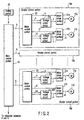
- FIG. 2 is a block diagram depicting a circuit configuration for carrying out an opening and closing control relevant to each of the shutters 10 in each of the stock hoppers 6a, 6b, ... 6h and each of the weighing hoppers 7a, 7b, ... 7h.
- a main control portion 18 that consists of a computer for controlling an operation of the entire combination weighing device, as shown in FIG. 1A, there are connected a plurality of shutter control portions 19a, 19b, ... 19g for controlling an opening and closing operation of shutters 10 in each of the stock hoppers 6a, 6b, ... 6h and each of the weighing hoppers 7a, 7b, ... 7h arranged along the peripheral face of the reverse cone shaped frame 1.
- the main control portion 18 delivers a feeder signal "f” to the dispersion feeder 4 and the forwarding feeder 5, and delivers a hopper release signal "g" to each of the shutter control portions 19a, 19b, ... 19h.
- various setting information is inputted from a setting portion 23 to the main control portion 18.
- each of the shutter control portions 19a, 19b, ... 19h energizing phases are sequentially changed from a motor control portion 20 to a motor drive circuit 21a of a stepping motor 17a for each of the stock hoppers 6a, 6b, ... 6h, and then, a drive pulse signal "a" for rotating the stepping motor 17a is applied.
- a hold current control signal "b" is inputted from the motor control portion 20 to the voltage output circuit 22a.
- This voltage output circuit 22a delivers to the motor drive circuit 21a a current limit signal "c" that corresponds to the inputted hold current control signal "b".
- this motor drive circuit 21a delivers to the stepping motor 17a a drive signal for rotatably driving the stepping motor 17a at a speed according to a pulse period of this drive pulse signal "a".
- the motor drive circuit 21a applies to the stepping motor 17a a hold current according to the current limit signal "c" from the voltage output circuit 22a.
- a drive pulse signal a 1 is applied to a motor drive circuit 21b of the stepping motor 17b for each of the weighing hoppers 7a, 7b, ... 7h.
- a hold current control signal b 1 is inputted from the motor control portion 20 to the voltage output circuit 22b.
- This voltage output circuit 22b delivers to the motor control circuit 21b a current limit signal c 1 that corresponds to the inputted hold current control signal b 1 .
- This motor control circuit 21b rotatably drives the stepping motor 17b at a speed according to a pulse period of the drive pulse signal a 1 , and applies to the stepping motor 17b a hold current according to the current limit signal c 1 .
- the voltage output circuits 22a and 22b for outputting such current limit signals "c" and "c 1 " are configured, respectively, as shown in FIG. 3.
- the hold current control signals "b" and “b 1 " are composed of a first hold current control signal b H and a second hold current control signal b L .
- a first transistor 26 is electrically conductive. Then, a voltage of the current limit signal "c" voltage divided by a voltage dividing resistors 24a and 24b is pulled down at a resistor 25.
- a second transistor 28 is electrically conductive. Then, a voltage of the current limit signal "c" voltage divided by the voltage dividing resistors 24a and 24b is pulled down at a resistor 27.
- the resistance value of the resistor 25 is set to be greater than that of the resistor 27.
- a current value of the first hold current applied to the stepping motors 17a and 17b during a period when the first hold current control signal b H is inputted is greater than that of the second hold current applied to the stepping motors 17a and 17b during a period when the second current control signal b L is inputted.
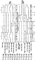
- a stock hopper release signal "g" corresponding to each of the stock hoppers 6a, 6b, ... 6h is inputted, whereby a drive pulse signal "a” is started to be outputted from a motor control portion 20 to a motor drive circuit 21.
- a stepping motor 17a starts a rotating operation, whereby, the shutter 10 of each of the stock hoppers 6a, 6b, ... 6h starts a release operation, as shown in FIG. 4D.
- a drive current 3A for example, is supplied to the stepping motor 17a, as shown in FIG. 4D.
- a feeder signal "f" is started to be outputted from the main control portion 18 to the forwarding feeder 5.
- a first hold current control signal b H is started to be outputted from the motor control portion 20 to the voltage output circuit 22a.
- a first hold current value (for example, 1 A) capable of applying to the shutter 10 a torque sufficient to bear the shock during charge of the materials 2 as the hold current applied to the stepping motor 17a from the start time for loading relevant to the shutter 10 caused by the materials 2 dropped from the material supply mechanism to each of the stock hoppers 6a, 6b, ... 6h to a predetermined period T 2 .
- a first hold current control signal b H falls.
- a second hold current control signal b L is started to be outputted from the motor control portion 20 to the voltage output circuit 22a.
- a second hold current value (for example, 0.1 A) is supplied, the second hold current value being smaller than the first hold current value capable of applying each of the shutters 10 a torque against a force of which each of the shutters 10 is released downwardly when a load is applied to the gravity direction of the materials 2, as a hold current applied to the stepping motor 17a.
- a first hold current value (for example, 1 A) capable of applying to each of the shutters 10 of each of the weighing hoppers 7a, 7b, ... 7h a torque sufficient to bear the shock during charge of the materials 2 as the hold current applied to the stepping motor 17b from the start time for loading relevant to the shutter 10 caused by the materials 2 dropped from each of the stock hoppers 6a, 6b, ... 6h into the each of the weighing hoppers 7a, 7b, ... 7h to the predetermined period T 4 .
- a first hold current value for example, 1 A
- a second hold current value (for example, 0.1 A) is supplied, the second hold current being smaller than the first hold current value capable of applying each of the shutters 10 of each of the weighing hoppers 7a, 7b, ... 7h a toque against a force released downwardly under a load in the gravity direction of the materials 2, as a hold current applied to the stepping motor 17b.
- a weighing hopper release signal "g" relevant to each of the weighing hoppers 7a, 7b, ... 7h is inputted from the main control portion 18 to the motor control portion 20.
- a drive pulse signal a 1 is started to be outputted from the motor control portion 20 to the motor drive circuit 21b.
- the stepping motor 17b starts a rotating operation, whereby the shutter 10 of each of the weighing hoppers 7a, 7b, ... 7h starts a release operation.
- a drive current 3A for example, is supplied to the stepping motor 17b, as shown in FIG. 4M.
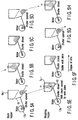
- FIGS. 5A to 5H are schematic views each showing a relationship between an operation of each of the stock hoppers 6a, 6b, ... 6h and an operation of each of the weighing hoppers 7a, 7b, ...7h achieved by the time charts shown in FIGS. 4A to 4M.
- an opening and closing operation of the shutter 10 of each of the weighing hoppers 7a, 7b, ... 7h is carried out to be slightly slower than that of the shutter 10 of each of the stock hoppers 6a, 6b, ... 6h.
- a first hold current flows the stepping motor 17a in which the shutter 10 of each of the stock hoppers 6a, 6b, ... 6h is closed.
- This first hold current has a current value capable of maintaining a holding force sufficient to bear the shock at the start of loading when the materials 2 are dropped to the shutter 10 of each of the stock hoppers 6a, 6b, ... 6h.
- the second hold current flows the stepping motor 17a in which the shutter 10 of each of the stock hoppers 6a, 6b, ... 6h is closed.
- this second hold current can be reduced from 1 A to 0.1 A described previously, which is about 1/6 to 1/8, and is further 1/10, as compared with the first hold current to which the shock is applied.
- the power consumption quantity of the entire combination weighing device can be reduced.
- an operation of the shutter 10 of each of the weighing hoppers 7a, 7b, ... 7h to which the materials 2 from each of the stock hoppers 6a, 6b, ... 6h are supplied (dropped) can provide a substantially similar advantageous effect.
- each of the shutter control portions 19a, 19b, ... 19h controls an operation so as to set the hold current applied to the motor from the start time for loading relevant to the shutter caused by the materials dropped from the material supply mechanism to the predetermined period, to a first hold current time capable of applying to the shutter a torque sufficient to bear the shock during charge of the materials, and to set a hold current applied to the motor from the elapse of the predetermined period after the materials have been received by the hopper to the start of discharging the materials from the discharge port of the hopper, to a second hold current value that is smaller than the first hold current value capable of applying to the shutter a torque against a force released downwardly under a load in the gravity direction of the materials.
- each of such shutter control ports 19a, 19b, ... 19h may control the hold current value so that an average current value of the hold currents applied to the motor is smaller in a period from reception of the materials by the hopper to the start of discharging the materials from the discharge port of the hopper, as compared with a hold current value relevant to the motor at the start of loading relevant to the shutter caused by the materials dropped from the material supply mechanism.
- FIG. 6 is a block diagram depicting a circuit configuration for carrying out opening and closing control relevant to each of the shutters 10 of each of the stock hoppers 6a, 6b, ... 6h and each of the weighing hoppers 7a, 7b, ... 7h in a combination weighing device incorporated by a material supply and discharge apparatus according to a second embodiment of the present invention.
- FIG. 6 like elements of the circuit block diagram according to the first embodiment shown in FIG. 2 are designated by line reference numerals. A duplicate detailed description is omitted here.
- a hold current condition setting table 29 is provided inside of the main control portion 18.
- a current adjuster circuit 30 is incorporated in each of the shutter control portions 19a, 19b, ... 19h.
- the hold current condition setting table 29 stores a current value of a first hold current and a period T 2 of applying the first hold current and a current value of a second hold current and a period T 3 of applying the second hold current or the like.
- the types of materials 2 include physical attributes of materials such as the weight, shape, and specific gravity of each material or a total weight of materials to be housed one time in one hopper, the physical attributes being a milestone of a shock during material drop or a static weight after dropped.
- the main control portion 18 reads out a current value of a first hold current of type specified by the hold current condition setting table 29 and a period T 2 of applying the first hold current; a current value of a second hold current and a period T 3 of applying the second hold current, and delivers them to each of the shutter control portions 19a, 19b, ... 19h.
- the motor control portion 20 of each of the shutter control portion 19a, 19b, ... 10h sets the period T 2 of applying the first holding current and the period T 3 of applying the second hold current to a period specified by the main control portion 18, and delivers the current value of the first hold current and the current value of the second current value to a current adjuster circuit 30.
- FIG. 7 is a detailed circuit diagram depicting voltage output circuits 22a and 22b of each of the shutter control portions 19a, 19b, ... 19h according to the second embodiment.
- the resistors 25 and 27 each in the voltage output circuits 22a and 22b according to the first embodiment shown in FIG. 3 are replaced with variable resistors 25a and 27a.
- the voltage adjuster circuit 30 adjusts the resistance value of each of the pull-down variable resistors 25a and 25b is adjusted so that the voltage limit signals "c" and "c 1 " are obtained as values that correspond to the current value of the first hold current and the current value of the second hold current that are specified by the motor control portion 30.
- each of the shutter control portions 19 can set the maximum first and second hold current values and the periods of applying the first and second hold currents as each of the hold currents of the stepping motors 17a and 17b according to type of material indicating physical attributes of materials to be weighed.
- power consumption of the entire apparatus can be reduced to its required minimum under a given condition.
- a ratio between the current value of the first hold current and the current value of the second hold current is highly set.
- the voltage limit signals "c" and “c 1 " specified by the motor control portion 20 via the D/A converter may be delivered to the motor drive circuits 21a and 21b when the first and second hold current signals b H , b L are inputted.
- FIGS. 8A to 8E are time charts each showing a shutter opening and closing operation of each of the stock hoppers 6a, 6b, ... 6h and each of the weighing hoppers 7a, 7b, ... 7h caused by the shutter control portion in the combination weighing device incorporated by a material supply and discharge apparatus according to a third embodiment of the present invention.
- a configuration other than shutter opening and closing operation of each of the stock hoppers 6a, 6b, ... 6h and each of the weighing hoppers 7a, 7b, ... 7h caused by this shutter control portion 19 is identical to that of the combination weighing device according to the second embodiment. A description of this configuration is omitted here.
- the release period T1 of the shutters 10 in each of the stock hoppers 6a, 6b, ... 6h and each of the weighing hoppers 7a, 7b, ... 7h is divided into an opening operation period and a closing operation period.
- FIG. 8A shows a degree of the shutter opening of each hopper.
- FIG. 8B shows a first hold current relevant to the stepping motors 17a and 17b.
- FIG. 8C shows a second hold current relevant to the stepping motors 17a and 17b.
- FIG. 8D shows torque characteristics "h" required for the stepping motors 17a and 17b.
- FIG. 8E shows a current limit signal relevant to the stepping motors 17a and 17b.
- the torque characteristic "h" required for the stepping motors 17a and 17b is obtained as a large value at an initial portion of the closing operation period and at an initial portion of the closing operation period.
- the torque value is substantially 0 at an intermediate point between the opening operation period in which the turning direction is inverted and the closing operation period.
- the energizing current supplied to the stepping motors 17a and 17b may be controlled to be indicated as a release period T 1 of the shutter 10 in FIG. 8E so as to be changed according to this torque characteristic "h".
- the shutter 10 of each hopper turns in a reverse direction when it is closed.
- the polarity of the torque characteristic "h" is inverted.
- the energizing current applied to the stepping motors 17a and 17b may be only in a forward direction. Therefore, as shown in FIG. 8D, the waveforms of the absolute values in torque characteristic "h" is desired.
- the current limit signals "c" and “c 1 " corresponding to the energizing current are indicated as a release period T1 of the shutter 10 shown in FIG. 8E, and are changed in response to the waveforms of the absolute values of the torque characteristic "h".
- the current value of the energizing current supplied to the stepping motors 17a and 17b is changed according to the opening and closing of the shutter 10 of each hopper, whereby wasteful power consumption can be restrained, and power consumption can be restrained while excellent shutter characteristics are maintained.
- the current limit signals "c" and "c1" delivered from the voltage output circuits 22a and 22b to the motor driver circuits 21a and 21b each may be controlled so as to be changed according to a change in torque during charge of the materials 2.
- the current voltage of the hold current applied to a motor while a shutter is closed is highly set during a period in which materials are continuously supplied into the hopper, and is lowly set during a period in which materials have been held in the hopper.
- the hold current value is controlled so that an average current value of a hold current applied to the motor is small in a duration from reception of the materials in the hopper to the start of discharging the hopper from the discharge port, as compared with a hold current value relevant to the motor at the start of loading relevant to the shutter caused by the materials dropped from the material supply mechanism.
- the material supply and discharge apparatus can restrain power consumption caused by a hold current applied to a motor during a period when a hopper shutter is closed while excellent shutter characteristics are maintained.
- a relationship between the hold current value when material loading starts and an average current value is adjusted according to physical attributes of materials supplied into the hopper.
- the current value of an energizing current supplied to a motor during a period of shutter opening and closing operation is controlled so as to be changed according to a change in torque required for opening and closing of the shutter.
- the hold current value supplied to a motor during a shutter closing period is controlled so as to be changed according to a change in torque during charge of the materials.
- the material supply and discharge apparatus can always restrain power consumption to its required minimum under a given condition.
- a material support and discharge apparatus in which the hold current relevant to a motor while the hopper shutter is closed is changed according to a material charge period and the subsequent period, whereby power consumption is restrained while excellent shutter characteristics can be maintained, and running cost can be reduced.
Landscapes
- Chemical & Material Sciences (AREA)
- Engineering & Computer Science (AREA)
- Ceramic Engineering (AREA)
- Materials Engineering (AREA)
- Chemical Kinetics & Catalysis (AREA)
- Structural Engineering (AREA)
- Organic Chemistry (AREA)
- Electrochemistry (AREA)
- General Chemical & Material Sciences (AREA)
- General Physics & Mathematics (AREA)
- Physics & Mathematics (AREA)
- Composite Materials (AREA)
- Filling Or Emptying Of Bunkers, Hoppers, And Tanks (AREA)
- Supply Of Fluid Materials To The Packaging Location (AREA)
- Cell Electrode Carriers And Collectors (AREA)
- Basic Packing Technique (AREA)
Abstract
A motor (17a, 17b) opens and closes a shutter
turnably mounted so as to open and close a discharge
port relevant to a hopper, and generates a torque
against a load in a gravity direction of materials
dropped from a material supply mechanism to the hopper.
A shutter control portion (19a, 19b, ... 19h) sets
a hold current applied to the motor from the start of
loading relevant to the shutter caused by the materials
to be dropped to a predetermined period, to a first
hold current value for applying to the shutter a torque
sufficient to bear the shock during charge of the
materials. In addition, the control portion sets a
hold current applied to the motor from an elapse of the
predetermined period after reception of the materials
by the hopper to the start of discharging the materials
from a discharge port of the hopper, to a second hold
current value that is smaller than the first hold
current value, the second hold current value applying
to the shutter a torque against a force released
downwardly under a load in the gravity direction of
the materials.
Description
- The present invention pertains to a material supply and discharge apparatus. More particularly, the present invention relates to a material supply and discharge apparatus having incorporated therein a hopper for temporarily holding a upwardly supplied material, and then, discharging the material from a downward discharge port.
- A packaging system for automatically packing a variety of materials in bags in a predetermined weight incorporates a combination weighing device for weighing separate materials sequentially supplied from the outside in combination.
- FIG. 9A is a schematic cross section showing a configuration of this combination weighing device.
- That is, a
funnel 3 for collectingseparate materials 2 such as confectionery or caramel, for example, supplied from the outside is arranged upwardly of a reverse cone shapedframe 1. -
Materials 2 collected by thisfunnel 3 are dispersed in a radiation manner by means of adispersion feeder 4 provided at the lower part of thefunnel 3. The thus dispersed materials are then supplied to stock hoppers 6 (only two hoppers shown) arranged along the peripheral face of the reverse cone shapedframe 1 by means of a plurality of forwardingfeeders 5 arranged in a radiation manner on theframe 1. - The
materials 2 supplied tostock hoppers 6 are temporarily held on thesestock hoppers 6. Then, as shown in FIG. 9B described later, ashutter 10 provided at the bottom of each of thesestock hoppers 6 is released, whereby the supplied materials are moved to a plurality of weighing hoppers 7 (only two hoppers shown) provided downwardly of each of thestock hoppers 6. - The weight of each of the
materials 2 moved to these weighinghoppers 7 is weighed for each of weighinghoppers 7. - That is, the weight of each of the
materials 2 carried inside of a respective one of a plurality of weighinghoppers 7 is weighed by a respective one of the plurality of weighinghoppers 7 arranged along the peripheral face of the reverse coneshaped frame 1. - Thereafter, there are selected each of the weighing
hoppers 7 housing thematerials 2 each of which a total of weight values obtained by combining the weight values of thematerials 2 for theweighing hoppers 7 each coincides with a predetermined weight value or is within the range of a predetermined tolerance. - As shown in FIG. 9B described later, the
shutters 10 each provided at the bottom of each of the selected weighinghoppers 7 are released, whereby thematerials 2 each are guided to acollection shoot 8 provided downwardly of each of the weighinghoppers 7. - Therefore, a bag (not shown) is placed downwardly of this
collection shoot 8, whereby thematerials 2 are housed in that bag by the predetermined weight value, and are automatically packed. - FIG. 9B is a schematic cross section of each of the
stock hoppers 6 and each of the weighinghoppers 7. - The
stock hoppers 6 each and theweighing hoppers 7 each have areceptacle port 9 for thematerials 2 at the upper end, and have adischarge port 11 for the materials formed at the lower end. - The previously described
shutter 10 for opening and closing thedischarge port 11 is mounted on ashaft 12 provided at one end of thisdischarge port 11. - A shaft of a
stepping motor 13, for example, is linked with thisshaft 12. - This stepping
motor 13 is driven, whereby theshutter 10 is turned, and thedischarge port 11 is controlled to be opened and closed. - Here, the stepping
motor 13 rotates theshaft 12 by an angle according to the number of pulses for a pulse driving current applied to an energizing coil. - Therefore, the number of pulses for the driving current applied to this stepping
motor 13 is controlled, whereby a rotation angle of the shaft of thestepping motor 13, i.e., an opening of theshutter 10 can be arbitrarily set. - In order to improve the operation response performance of the
shutter 10, it is desirable to use thestepping motor 13 rather than a general direct current motor or inductive motor. - However, in a combination weighing device configured as shown in FIGS. 9A and 9B as well, the following problems remain unsolved.
- That is, this combination weighing device is not executed by sliding a shutter opening and closing operation in order to ensure high response characteristics in shutter opening and closing operation. As shown in FIG. 9B, the weighing device is executed by fixing one end of the
shutter 10 to theshaft 12, and then, rotating thisshaft 12 by means of the steppingmotor 13. - In a state in which
materials 2 are housed in each of thestock hoppers 6 or each of the weighinghoppers 7, the load in the gravity direction of thematerials 2 is applied to theshutter 10. - In the case where the
shutter 10 is of slide type, the load in this gravity direction is subjected to a shutter holding mechanism, for example, a slide groove. - Hence, as shown in FIG. 9B, in a system for the
shutter 10 to turn around theshaft 12, while theshutter 10 is closed, a hold current is fed to the steppingmotor 13 linked with theshaft 12, thereby making it necessary to prevent theshutter 10 from turning when the load in the gravity direction of thematerials 2 is applied. - In the meantime, while the
shutter 10 is closed, it is general that thematerials 2 are charged (dropped) intensively within a short period of time instead of being charged (dropped) continuously. - Therefore, the load in the gravity direction is not uniformly applied to the
shutter 10 while theshutter 10 is closed. The load value is greater than the weight of thematerials 2 by a shock applied while the materials are charged for a short period of time. - In order to prevent the
shutter 10 from being opened due to this shock applied when thematerials 2 are charged, it is required to set a hold current relevant to the steppingmotor 13 to a hold current value such that the steppingmotor 13 can apply to the shutter 10 a torque sufficient to bear the shock when thematerials 2 are charged. - In this case, as described above, the
materials 2 relevant to all the periods in which theshutters 10 in each of thestock hoppers 6 and each of the weighinghoppers 7 are closed are charged intensively within a short period of time. - Therefore, feeding a hold current bearing the shock when the
materials 2 are charged to the steppingmotor 13 all over the period when theshutters 10 are closed, including a period after the materials have been charged, causes wasteful power consumption. - In particular, in a combination weighing device as shown in FIG. 9A, there are provided a number of
stock hoppers 6 and a number of weighinghoppers 7 arranged along the peripheral face of the reverse cone shapedframe 1. Thus, there occurs a problem that power consumption of the entire device increases, and the running cost of the combination weighing device increases. - When the
shutter 10 is closed, theshutter 10 is suspended by a spring or the like against the load in the gravity direction of thematerials 2, whereby the hold current relevant to thestepping motor 13 can be eliminated. - However, this spring is always connected. Therefore, in the case of opening the
shutter 10, it is required to feed to the stepping motor an energizing current sufficient to overcome the biasing force of this spring, which causes wasteful power consumption. - The present invention has been made in order to solve the foregoing problem. It is an object of the present invention to provide a material supply and discharge apparatus for changing a hold current relevant to a motor in a state in which a hopper shutter is closed according to a material charge period and the subsequent period, thereby making it possible to restrain power consumption and reduce running cost while maintaining excellent shutter characteristics.
- According to a first aspect of the present invention, in order to achieve the foregoing object, there is provided a material supply and discharge apparatus comprising:
- a hopper (6a, 7a) having a receptacle port for materials at an upper end thereof and a discharge port for the materials at a lower end thereof;
- a material supply mechanism (4, 5, 6a) disposed upwardly of the hopper, the mechanism causing the materials to be dropped from the reception port into the hopper;
- shutter (10) turnably mounted so as to open and close the discharge port relevant to the hopper, the shutter being driven to be opened and closed so as to be released downwardly under a load in the gravity direction of the materials when the materials are dropped from the material supply mechanism after the discharge port has been closed in order to temporarily hold the materials in the hopper;
- a motor (17a, 17b) linked with the shutter in order to drive the shutter to be opened and closed, a holding current being applied during closing of the shutter, thereby the shutter imparting to the shutter a torque against a force released downwardly by the load in the gravity direction of the materials; and
- a shutter control portion (19a) for setting the hold current applied to the motor from the start time for loading applied to the shutter caused by the materials dropped from the material supply mechanism to a predetermined period, to a first hold current value capable of applying to the shutter a torque bearing a shock when the materials are charged, and setting a hold current applied to the motor from after an elapse of the predetermined period to the start of discharge from a discharge port of the hopper to a second hold current value smaller than the first hold current value capable of applying to the shutter a toque against a force released downwardly under a load in the gravity direction of the materials.
-
- In the material supply and discharge apparatus configured according to the first aspect, while the shutter of the hopper is closed, at the start of loading applied to the shutter when materials are started to be charged (dropped) into the hopper from the material supply mechanism, a high hold current sufficient to bear the shock is fed to the motor. However, after the start time for material charge (drop) into the hopper has elapsed, the hold current relevant to the motor may be smaller than a hold current when charging (dropping) is started. Therefore, power consumption caused by a hold current in a period when the hopper shutter is closed can be restrained.
- According to a second aspect of the present invention, in order to achieve the foregoing object, there is provided a material supply and discharge apparatus according to the first aspect, wherein the shutter control portion (19a) comprises a motor control portion (20) for controlling the holding current so that an average current value of the hold current applied to the motor is reduced until the materials has been started to be discharged from the hopper discharge port after the materials have been received by the hopper as compared with the hold current value relevant to the motor at the start of loading relevant to the shutter caused by the materials dropped from the material supply mechanism.
- In the material supply and discharge apparatus configured according to the second aspect, as in the first aspect, while the shutter of the hopper is closed, at the start of loading relevant to the shutter caused by the materials being started to be charged (dropped) into the hopper from the material supply mechanism, a high hold current sufficient to bear the shock is fed to the motor. However, after the start time for material charge (drop) into the hopper has elapsed, a motor hold current may be smaller than a hold current when charging (dropping) starts. Therefore, power consumption caused by a hold current in a period when the hopper shutter is closed can be restrained.
- According to a third aspect of the present invention, in order to achieve the foregoing object, there is provided a material supply and discharge apparatus according to the first aspect, further comprising hold current adjusting means (29, 30) for adjusting a relationship between the first hold current value and second hold current value relevant to the motor at the start of the loading according to physical attributes of materials supplied into the hopper from the material supply mechanism.
- According to a fourth aspect of the present invention, there is provided a material supply and discharge apparatus according to the second aspect, further comprising hold current adjusting means (29, 30) for adjusting a relationship between the first hold current value relevant to the motor at the start of the loading and the average current value according to physical attributes of materials supplied into the hopper from the material supply mechanism.
- In the material supply and discharge apparatus configure according to the third and fourth aspects, a relationship between a hold current value when loading starts and an average current value is adjusted according to physical attributes such as weight per material to be charged (dropped) into a hopper, a total weight, or shape.
- That is, according to the material supply and discharge apparatus configured according to the third and fourth aspects, the shock greatly varies depending on the physical attributes of the materials. Thus, the hold current value when the most efficient loading starts can be selected.
- According to a fifth aspect of the present invention, there is provided a material supply and discharge apparatus according to the third aspect, wherein the hold current adjusting means (29, 30) comprises a hold current condition setting table (29) and a current adjuster circuit (30), wherein the first hold current value and a period of applying the first hold current and the second hold current value and a period of applying the second hold current or the like are stored for each of types of the materials in the hold current condition setting table, and the types of materials primarily include physical attributes of materials such as the weight, shape, and specific gravity of each material or a total weight of materials to be housed one time in one hopper, the physical attributes being a milestone of a shock during material drop or a static weight after dropped; wherein the shutter control portion sets a period of applying the first hold current and a period of applying the second hold current as periods specified according to type of the material from the hold current condition setting table; and wherein the current adjuster circuit sets the first hold current value and second hold current value as current values specified according to type of the material from the hold current condition setting table.
- In addition, according to a sixth aspect of the present invention, in order to achieve the foregoing object, there is provided a material supply and discharge apparatus according to the fourth aspect, wherein the hold current adjusting means (29, 30) comprises a hold current condition setting table (29) and a current adjuster circuit (30), wherein a hold current value relevant to the motor when the loading starts and a period of applying the hold current and the average current value and a period of applying the average value are stored for each type of the material in the hold current condition setting table, and types of the materials primarily include physical attributes of materials such as the weight, shape, and specific gravity of each material or a total weight of materials to be housed one time in one hopper, the physical attributes being a milestone of a shock during a material drop or a static weight after dropped; wherein the shutter control portion sets a period of applying a hold current to the motor when the loading starts from the hold current condition setting table and a period of applying the average current as periods specified according to type of the material; and wherein the current adjuster circuit sets the hold current value relevant to the motor when the loading starts from the hold current condition setting table and the average current value as current values specified according to type of the material.
- In addition, according to a seventh aspect of the present invention, in order to achieve the foregoing object, there is provided a material supply and discharge apparatus according to the first or second aspect, wherein the shutter control portion (19a) controls a current value of an energizing current supplied to the motor according to a change of a torque required for opening and closing of the shutter during a period for opening and closing operation of the shutter.
- In general, a torque required for opening and closing a shutter turnably mounted on a hopper discharge port is not constant during an opening and closing period, and greatly changes.
- That is, a large torque is required at the initial state of a shutter opening operation or at the initial stage of a closing operation. When a predetermined period of time has elapsed, the required torque is reduced.
- Because of this, at the initial stage of a shutter opening operation requiring a large torque or during a closing operation, it is required to increase an energizing current supplied to a motor. Conversely, when a small torque is applied after the predetermined period of time has elapsed, the energizing current supplied to the motor may be reduced.
- Therefore, in the material supply and discharge apparatus configured according to the seventh aspect, a current value of an energizing current supplied to the motor is changed according to a change of a torque required for opening and closing of the shutter, whereby wasteful power consumption can be restrained, and power consumption can be restrained while maintaining excellent shutter characteristics.
- In addition, according to an eighth aspect of the present invention, there is provided a material supply and discharge apparatus according to the first or second aspect, wherein the shutter control portion (19a) controls the hold current value so as to be changed according to a change of a torque when the material is charged.
- In the material supply and discharge apparatus configured according to the eighth aspect, a hold current value supplied to the motor is changed according to a change of a torque during material charge, whereby wasteful power consumption can be restrained, and power consumption can be restrained while maintaining excellent shutter characteristics.
- In addition, according to a ninth aspect of the present invention, in order to achieve the foregoing object, there is provided a material supply and discharge apparatus according to the first or second aspect, wherein the shutter control portion (19a) comprises:
- a motor control portion (20) for outputting a motor drive signal and a hold current control signal based on a hopper release signal from a main control portion (18);
- a voltage output circuit (22a) for outputting a current limit signal based on the hold current control signal from the motor control portion; and
- a motor driver circuit (21a) for supplying a drive signal based on the motor drive signal from the motor control portion and the current limit signal from the voltage output circuit.
-
- In addition, according to a tenth aspect of the present invention, in order to achieve the foregoing object, there is provided a material supply and discharge apparatus according to the ninth aspect, wherein, when the hold current control signal from the motor control portion is composed of a first hold current control signal and a second hold current control signal, the voltage output circuit (22a) comprises:
- a first transistor (26) that is electrically conductive during a period when the first hold current control signal is inputted from the motor control portion;
- first resistance means (25) for, when the first transistor is electrically conductive, providing a first current limit signal;
- a second transistor (28) that is electrically conductive during a period when the second hold current control signal is inputted from the motor control portion; and
- second resistance means (27) for, when the second transistor is electrically conductive, providing a second current limit signal, wherein the motor driver circuit (21a) changes a current value of the hold current supplied to the motor based on the first and second current limit signal.
-
- In addition, according to an eleventh aspect of the present invention, in order to achieve the foregoing object, there is provided a material supply and discharge apparatus according to the first or second aspect, wherein the shutter control portion (19a) comprises:
- a motor control portion (20) for outputting a motor drive signal, a hold current control signal, and a current adjusting signal based on a hopper release signal from a main control portion (18);
- a voltage output circuit (22a) for outputting a current limit signal based on the hold current control signal from the motor control portion;
- a motor driver circuit (21a) for supplying a drive signal to the motor based on a motor drive signal from the motor control portion and the current limit signal from the voltage output circuit; and
- a current adjuster circuit (30) for adjusting the current limit signal caused by the voltage output circuit based on the current adjusting signal from the motor control portion.
-
- In addition, according to a twelfth aspect of the present invention, in order to achieve the foregoing object, there is provided a material supply and discharge apparatus according to the eleventh aspect, wherein, when the hold current control signal from the motor control portion is composed of a first hold current control signal and a second hold current control signal, the voltage output circuit (22a) comprises:
- a first transistor (26) that is electrically conductive during a period when the first hold current control signal is inputted from the motor control portion;
- a first variable resistor (25a) for, when the first transistor is electrically conductive, providing a first current limit signal;
- a second transistor (28) that is electrically conductive during a period when the second hold current control signal is inputted from the motor control portion; and
- a second variable resistor (27a) for, when the second transistor is electrically conductive, providing a second current limit signal, wherein the current adjuster circuit (30) varies the first and second variable resistance based on the current adjusting signal, thereby adjusting the first and second current limit signal, and wherein the motor drive circuit (21a) changes a current value of the hold current supplied to the motor based on the first and second current limit signal.
-
-
- FIGS. 1A, 1B, and 1C are a plan view, a side view, and a partial view showing a schematic configuration of a combination weighing device incorporated by a material supply and discharge apparatus according to a first embodiment of the present invention, respectively.
- FIG. 2 is a block diagram depicting a circuit configuration of a combination weighing device incorporated by the material supply and discharge apparatus according to the first embodiment of the present invention.
- FIG. 3 is a block diagram depicting an internal configuration of a voltage output circuit shown in FIG. 2.
- FIGS. 4A to 4M are time charts each illustrating a shutter opening and closing control operation of the combination weighing device incorporated by the material supply and discharge apparatus according to the first embodiment of the present invention.
- FIGS. 5A to 5H are views each illustrating a shutter opening and closing operation in each hopper of the combination weighing device incorporated by the material supply and discharge apparatus according to the first embodiment of the present invention.
- FIG. 6 is a block diagram depicting a circuit configuration of the combination weighing apparatus incorporated by a material supply and discharge apparatus according to a second embodiment of the present invention.
- FIG. 7 is a block diagram depicting an internal configuration of a voltage output circuit shown in FIG. 6.
- FIGS. 8A to 8E are time charts each illustrating a shutter opening and closing control operation of a combination weighing device incorporated by a material supply and discharge apparatus according to a third embodiment of the present invention.
- FIGS. 9A and 9B are a side view and a partial view each schematically showing a configuration of a general, conventional combination weighing device.
-
- Hereinafter, preferred embodiments of the present invention will be described with reference to the accompanying drawings.
- FIGS. 1A, 1B, and 1C are views each showing a schematic configuration of a combination weighing device incorporated by a material supply and discharge apparatus according to a first embodiment of the present invention.
- FIG. 1A is a top view of the combination weighing device.
- FIG. 1B is a schematic cross section of the combination weighing device.
- FIG. 1C is a schematic cross section of each hopper in FIGS. 1A and 1B.
- In FIGS. 1A, 1B, and 1C, like elements of the conventional weighing device shown in FIG. 9A are designated by like reference numerals. A duplicate detailed description is omitted here.
- In the combination weighing device according to the first embodiment,
materials 2 collected by afunnel 3 are dispersed in a radiation manner by means of adispersion feeder 4 provided at the lower part of thefunnel 3. The thus dispersed materials are then supplied to a plurality ofstock hoppers frame 1 by means of a plurality of forwardingfeeders 5 arranged in a radiation manner on theframe 1. - The
materials 2 supplied to thestock hoppers stock hoppers shutters 10 are provided respectively at the bottom of each of thestock hoppers 6, whereby the materials are moved to eight weighinghoppers stock hoppers - The weight of each of the materials moved to these weighing
hoppers hoppers - That is, the weight value of such each
material 2 carried inside of a respective one of a plurality of weighinghoppers hoppers frame 1. - Then, there are selected weighing
hoppers materials 2 each are combined for each of the weighinghoppers - Then, as shown in FIG. 1C described later,
shutters 10 are provided respectively at the bottom of each of the weighinghoppers materials 2 each are guided to acollection shoot 8 provided downwardly of each of the selected weighinghoppers - Therefore, a bag (not shown) is placed downwardly of this
collection shoot 8, wherebymaterials 2 each are housed in that bag by a predetermined weight value, and are automatically packed. - The
funnel 3,dispersion feeder 4, and a plurality of forwardingfeeder 5 configure a material supply mechanism for supplying (dropping)materials 2 in each of thestock hoppers - The
stock hoppers materials 2 in each of the weighinghoppers stock hoppers - FIG. 1C is a schematic cross section representing one of the
stock hoppers hoppers - The
stock hoppers hoppers receptacle port 9 formaterials 9 at an upper end, and has adischarge 2 at a lower end.port 11a materials - One end of the previously described
shutter 10 for opening and closing thedischarge port 11a is pivoted at ashaft 12a provided at one end of thisdischarge port 11a - In addition, one end of a
rod 16 is pivoted at a tip end of acrank 15 mounted on a rotary shaft of each of 16stepping motors - The other end of this
rod 16 is pivoted on the outer surface of a respective one of theshutters 10 of each of thestock hoppers hoppers - Therefore, when a
rotary shaft 14 of each of thestepping motors discharge port 11a and further, changes its state from the opened state to the closed state. - Therefore, in order to move (drop)
materials 2 each housed in each of thestock hoppers hoppers discharge port 11a, therotary shaft 14 of each of thestepping motors - FIG. 2 is a block diagram depicting a circuit configuration for carrying out an opening and closing control relevant to each of the
shutters 10 in each of thestock hoppers hoppers - That is, to a
main control portion 18 that consists of a computer for controlling an operation of the entire combination weighing device, as shown in FIG. 1A, there are connected a plurality ofshutter control portions shutters 10 in each of thestock hoppers hoppers frame 1. - In the first embodiment, eight
shutter control portions main control portion 18. - Here, the
main control portion 18 delivers a feeder signal "f" to thedispersion feeder 4 and the forwardingfeeder 5, and delivers a hopper release signal "g" to each of theshutter control portions - In addition, various setting information is inputted from a setting
portion 23 to themain control portion 18. - In each of the
shutter control portions motor control portion 20 to amotor drive circuit 21a of a steppingmotor 17a for each of thestock hoppers motor 17a is applied. - In addition, when the stepping
motor 17a is inactive, a hold current control signal "b" is inputted from themotor control portion 20 to thevoltage output circuit 22a. - This
voltage output circuit 22a delivers to themotor drive circuit 21a a current limit signal "c" that corresponds to the inputted hold current control signal "b". - When a drive pulse signal "a" is inputted from the
motor control portion 20, thismotor drive circuit 21a delivers to the steppingmotor 17a a drive signal for rotatably driving the steppingmotor 17a at a speed according to a pulse period of this drive pulse signal "a". - Further, when the stepping
motor 17a is inactive, themotor drive circuit 21a applies to the steppingmotor 17a a hold current according to the current limit signal "c" from thevoltage output circuit 22a. - Similarly, from the
motor control portion 20, a drive pulse signal a1 is applied to amotor drive circuit 21b of the steppingmotor 17b for each of the weighinghoppers - In addition, when the stepping
motor 17b is inactive, a hold current control signal b1 is inputted from themotor control portion 20 to thevoltage output circuit 22b. - This
voltage output circuit 22b delivers to themotor control circuit 21b a current limit signal c1 that corresponds to the inputted hold current control signal b1. - This
motor control circuit 21b rotatably drives the steppingmotor 17b at a speed according to a pulse period of the drive pulse signal a1, and applies to the steppingmotor 17b a hold current according to the current limit signal c1. - Therefore, as shown in FIGS. 4G and 4M, when the
stepping motors - The
voltage output circuits - That is, the hold current control signals "b" and "b1" are composed of a first hold current control signal bH and a second hold current control signal bL.
- In the
voltage output circuits first transistor 26 is electrically conductive. Then, a voltage of the current limit signal "c" voltage divided by avoltage dividing resistors resistor 25. - In addition, during a period when the second hold current control signal bL is inputted, a
second transistor 28 is electrically conductive. Then, a voltage of the current limit signal "c" voltage divided by thevoltage dividing resistors resistor 27. - Here, the resistance value of the
resistor 25 is set to be greater than that of theresistor 27. - Therefore, a current value of the first hold current applied to the
stepping motors stepping motors - Now, a shutter control operation of each of the thus configured
shutter control portions - First, a control operation of each of the
shutters 10 relevant to each of thestock hoppers - At a time t1, from the
main control portion 18, as shown in FIGS. 4B and 4C, a stock hopper release signal "g" corresponding to each of thestock hoppers motor control portion 20 to a motor drive circuit 21. - Then, a stepping
motor 17a starts a rotating operation, whereby, theshutter 10 of each of thestock hoppers - Then, at a time t3 after a release period T1 has elapsed, when the stock hopper release signal "g" falls, an output of the drive pulse signal "a" from the
motor control portion 20 is stopped, whereby the steppingmotor 17a is stopped, and theshutter 10 of each of thestock hoppers - In this case, at the release period T1, a drive current 3A, for example, is supplied to the stepping
motor 17a, as shown in FIG. 4D. - At a time t3, when the
shutter 10 of each of thestock hoppers main control portion 18 to the forwardingfeeder 5. At the same time, as shown in FIG. 4E, a first hold current control signal bH is started to be outputted from themotor control portion 20 to thevoltage output circuit 22a. - In this manner, as shown in FIG. 4G, to an
inactive stepping motor 17a, there is supplied a first hold current value (for example, 1 A) capable of applying to the shutter 10 a torque sufficient to bear the shock during charge of thematerials 2 as the hold current applied to the steppingmotor 17a from the start time for loading relevant to theshutter 10 caused by thematerials 2 dropped from the material supply mechanism to each of thestock hoppers - Then, when a feeder signal "f" rises at a time t4 after the period T2 has been elapsed, a first hold current control signal bH falls. Then, as shown in FIG. 4F, a second hold current control signal bL is started to be outputted from the
motor control portion 20 to thevoltage output circuit 22a. - In this manner, as shown in FIG. 4G, after the materials each 2 has been received by each of the
stock hoppers discharge port 11a of each of thestock hoppers shutters 10 is released downwardly when a load is applied to the gravity direction of thematerials 2, as a hold current applied to the steppingmotor 17a. - Then, at a time t7 after the period T3 has elapsed, when the second hold current control signal bL falls, the
shutter 10 of each of thestock hoppers - Now, a description will be given with respect to a control operation of each of the
shutters 10 relevant to each of the weighinghoppers stock hoppers - First, at a period T4 from a time t0 immediately before the
shutter 10 of each of thestock hoppers shutter 10 of each of thestock hoppers motor 17b is inactive, the first hold current control signal bH is outputted from themotor control portion 20 to thevoltage output circuit 22b. - In this manner, as shown in FIG. 4M, to an
inactive stepping motor 17b, there is supplied a first hold current value (for example, 1 A) capable of applying to each of theshutters 10 of each of the weighinghoppers materials 2 as the hold current applied to the steppingmotor 17b from the start time for loading relevant to theshutter 10 caused by thematerials 2 dropped from each of thestock hoppers hoppers - Then, when this first hold current control signal bH falls at the time t2, as shown in FIG. 4L, the second hold current control signal bL is started to be outputted from the
motor control portion 20 to thevoltage output circuit 22b. - In this manner, as shown in FIG. 4M, at a period T5 from t2 to t5, from an elapse of the predetermined period T4 after the materials each have been received by each of the weighing
hoppers materials 2 from thedischarge port 11a of each of thestock hoppers shutters 10 of each of the weighinghoppers materials 2, as a hold current applied to the steppingmotor 17b. - Then, at a time t5 after the period T5 has elapsed, when the second hold current control signal bL falls, as shown in FIG. 4H, a weighing hopper release signal "g" relevant to each of the weighing
hoppers main control portion 18 to themotor control portion 20. - In this manner, as shown in FIG. 4I, a drive pulse signal a1 is started to be outputted from the
motor control portion 20 to themotor drive circuit 21b. - Then, as shown in FIG. 4I, the stepping
motor 17b starts a rotating operation, whereby theshutter 10 of each of the weighinghoppers - Then, at a time t6 after a period t6 has elapsed, when a weighing hopper release signal falls, an output of the drive pulse signal a1 is stopped, whereby the shutter of each of the weighing
hoppers - In this case, at the release period T6, a drive current 3A, for example, is supplied to the stepping
motor 17b, as shown in FIG. 4M. - FIGS. 5A to 5H are schematic views each showing a relationship between an operation of each of the
stock hoppers hoppers - As shown in FIGS. 5A to 5H, it is understandable that an opening and closing operation of the
shutter 10 of each of the weighinghoppers shutter 10 of each of thestock hoppers - That is, during a period when the
shutter 10 of each of thestock hoppers materials 2 are dropped, theshutter 10 of each of the weighinghoppers - In a combination weighing device incorporated by the thus configured material supply and discharge apparatus according to the first embodiment, when
materials 2 are started to be supplied (dropped) from the forwardingfeeder 5 to each of thestock hoppers motor 17a in which theshutter 10 of each of thestock hoppers - This first hold current has a current value capable of maintaining a holding force sufficient to bear the shock at the start of loading when the
materials 2 are dropped to theshutter 10 of each of thestock hoppers - Therefore, due to the shock, the
materials 2 are not dropped downwardly without the release of theshutter 10 of each of thestock hoppers - Then, at a time when the supply (drop) of the
materials 2 from the forwardingfeeder 5 to each of thestock hoppers motor 17a in which theshutter 10 of each of thestock hoppers - At this period, the weight of each of the
materials 2 housed in each of thestock hoppers shutter 10 of each of thestock hoppers - Therefore, this second hold current can be reduced from 1 A to 0.1 A described previously, which is about 1/6 to 1/8, and is further 1/10, as compared with the first hold current to which the shock is applied.
- Therefore, the power consumption quantity of the entire combination weighing device can be reduced.
- In addition, an operation of the
shutter 10 of each of the weighinghoppers materials 2 from each of thestock hoppers - In the present embodiment, each of the
shutter control portions - Hence, each of such
shutter control ports - FIG. 6 is a block diagram depicting a circuit configuration for carrying out opening and closing control relevant to each of the
shutters 10 of each of thestock hoppers hoppers - In FIG. 6, like elements of the circuit block diagram according to the first embodiment shown in FIG. 2 are designated by line reference numerals. A duplicate detailed description is omitted here.
- In the second embodiment, a hold current condition setting table 29 is provided inside of the
main control portion 18. - Further, a
current adjuster circuit 30 is incorporated in each of theshutter control portions - Here, the hold current condition setting table 29 stores a current value of a first hold current and a period T2 of applying the first hold current and a current value of a second hold current and a period T3 of applying the second hold current or the like.
- The types of
materials 2 include physical attributes of materials such as the weight, shape, and specific gravity of each material or a total weight of materials to be housed one time in one hopper, the physical attributes being a milestone of a shock during material drop or a static weight after dropped. - Then, if an operator specifies type of
material 2 to be weighed by operating a settingportion 2 before actually starting weighing, themain control portion 18 reads out a current value of a first hold current of type specified by the hold current condition setting table 29 and a period T2 of applying the first hold current; a current value of a second hold current and a period T3 of applying the second hold current, and delivers them to each of theshutter control portions - The
motor control portion 20 of each of theshutter control portion main control portion 18, and delivers the current value of the first hold current and the current value of the second current value to acurrent adjuster circuit 30. - FIG. 7 is a detailed circuit diagram depicting
voltage output circuits shutter control portions - In the
voltage output circuits resistors voltage output circuits variable resistors - Then, the
voltage adjuster circuit 30 adjusts the resistance value of each of the pull-downvariable resistors 25a and 25b is adjusted so that the voltage limit signals "c" and "c1" are obtained as values that correspond to the current value of the first hold current and the current value of the second hold current that are specified by themotor control portion 30. - When an operator activates this combination weighing device after the above condition setting process has completed, the current value of the hold current of the
stepping motors - In the thus configured combination weighing device incorporated by the material supply and discharge apparatus according to the second embodiment, each of the shutter control portions 19 can set the maximum first and second hold current values and the periods of applying the first and second hold currents as each of the hold currents of the
stepping motors - For example, under the condition where a total weight of a plurality of
materials 2 to be housed in one hopper is equal to a predetermined weight, in the case where the weight of onematerial 2 is greater, the shock becomes larger. Thus, a ratio between the current value of the first hold current and the current value of the second hold current is highly set. - In addition, in the case where the weight of one
material 2 is smaller, the shock becomes smaller. Thus, a ratio between the current value of the first hold current and the current value of the second hold current is lowly set. - In addition, in the case where the weight of one
material 2 is greater, the shock and vibration become greater. Thus, a time for applying the first hold current is set to be longer. - In addition, in the case where the weight of one
material 2 is smaller, the shock and vibration become smaller. Thus, a time for applying the first hold current is set to be shorter. - When the
current adjuster circuit 30 andvoltage output circuits motor control portion 20 via the D/A converter may be delivered to themotor drive circuits - FIGS. 8A to 8E are time charts each showing a shutter opening and closing operation of each of the
stock hoppers hoppers - A configuration other than shutter opening and closing operation of each of the
stock hoppers hoppers - In the time charts shown in FIGS. 8A to 8E, the release period T1 of the
shutters 10 in each of thestock hoppers hoppers - FIG. 8A shows a degree of the shutter opening of each hopper.
- FIG. 8B shows a first hold current relevant to the
stepping motors - FIG. 8C shows a second hold current relevant to the
stepping motors - FIG. 8D shows torque characteristics "h" required for the
stepping motors - FIG. 8E shows a current limit signal relevant to the
stepping motors - In order to smoothly carry out an opening and closing operation in the
shutter 10 of each hopper, the torque characteristic "h" required for thestepping motors - With respect to the
shutter 10 of each hopper, the torque value is substantially 0 at an intermediate point between the opening operation period in which the turning direction is inverted and the closing operation period. - Therefore, the energizing current supplied to the
stepping motors shutter 10 in FIG. 8E so as to be changed according to this torque characteristic "h". - The
shutter 10 of each hopper turns in a reverse direction when it is closed. Thus, the polarity of the torque characteristic "h" is inverted. However, the energizing current applied to thestepping motors - Hence, the current limit signals "c" and "c1" corresponding to the energizing current, these signals being delivered from the
voltage output circuits motor driver circuits shutter 10 shown in FIG. 8E, and are changed in response to the waveforms of the absolute values of the torque characteristic "h". - In this way, the current value of the energizing current supplied to the
stepping motors shutter 10 of each hopper, whereby wasteful power consumption can be restrained, and power consumption can be restrained while excellent shutter characteristics are maintained. - At a charge period T2 of
materials 2, in the case where a change in required torque occurs, as indicated as a charge period T2 ofmaterials 2 in FIG. 8E, the current limit signals "c" and "c1" delivered from thevoltage output circuits motor driver circuits materials 2. - As has been described above, in the material supply and discharge apparatus according to the present invention, the current voltage of the hold current applied to a motor while a shutter is closed is highly set during a period in which materials are continuously supplied into the hopper, and is lowly set during a period in which materials have been held in the hopper.
- In addition, in the material supply and discharge apparatus according to the present invention, the hold current value is controlled so that an average current value of a hold current applied to the motor is small in a duration from reception of the materials in the hopper to the start of discharging the hopper from the discharge port, as compared with a hold current value relevant to the motor at the start of loading relevant to the shutter caused by the materials dropped from the material supply mechanism.
- Therefore, the material supply and discharge apparatus according to the present invention can restrain power consumption caused by a hold current applied to a motor during a period when a hopper shutter is closed while excellent shutter characteristics are maintained.
- In addition, in the material supply and discharge apparatus according to the present invention, a relationship between the hold current value when material loading starts and an average current value is adjusted according to physical attributes of materials supplied into the hopper.
- Further, in the material supply and discharge apparatus according to the present invention, the current value of an energizing current supplied to a motor during a period of shutter opening and closing operation is controlled so as to be changed according to a change in torque required for opening and closing of the shutter.
- Furthermore, in the material supply and discharge apparatus according to the present invention, the hold current value supplied to a motor during a shutter closing period is controlled so as to be changed according to a change in torque during charge of the materials.
- As has been described above, the material supply and discharge apparatus according to the present invention can always restrain power consumption to its required minimum under a given condition.
- Therefore, according to the present invention, there can be provided a material support and discharge apparatus in which the hold current relevant to a motor while the hopper shutter is closed is changed according to a material charge period and the subsequent period, whereby power consumption is restrained while excellent shutter characteristics can be maintained, and running cost can be reduced.
Claims (12)
- A material supply and discharge apparatus comprising:a hopper having a receptacle port for materials at an upper end thereof and a discharge port for the materials at a lower end thereof;a material supply mechanism disposed upwardly of the hopper, the mechanism causing the materials to be dropped from the reception port into the hopper;a shutter turnably mounted so as to open and close the discharge port relevant to the hopper, the shutter being driven to be opened and closed so as to be released downwardly under a load in the gravity direction of the materials when the materials are dropped from the material supply mechanism after the discharge port has been closed in order to temporarily hold the materials in the hopper;a motor linked with the shutter in order to drive the shutter to be opened and closed, a holding current being applied during closing of the shutter, thereby the shutter imparting to the shutter a torque against a force released downwardly by the load in the gravity direction of the materials; anda shutter control portion for setting the hold current applied to the motor from the start time for loading applied to the shutter caused by the materials dropped from the material supply mechanism to a predetermined period, to a first hold current value capable of applying to the shutter a torque bearing a shock when the materials are charged, and setting a hold current applied to the motor from after an elapse of the predetermined period to the start of discharge from a discharge port of the hopper to a second hold current value smaller than the first hold current value capable of applying to the shutter a toque against a force released downwardly under a load in the gravity direction of the materials.
- A material supply and discharge apparatus according to claim 1, wherein the shutter control portion comprises a motor control portion for controlling the holding current so that an average current value of the hold current applied to the motor is reduced until the materials has been started to be discharged from the hopper discharge port after the materials have been received by the hopper as compared with the hold current value relevant to the motor at the start of loading relevant to the shutter caused by the materials dropped from the material supply mechanism.
- A material supply and discharge apparatus according to claim 1, further comprising hold current adjusting means for adjusting a relationship between the first hold current value and second hold current value relevant to the motor at the start of the loading according to physical attributes of materials supplied into the hopper from the material supply mechanism.
- A material supply and discharge apparatus according to claim 2, further comprising hold current adjusting means for adjusting a relationship between a hold current value relevant to the motor when the loading starts and the average current value according to physical attributes of materials supplied into the hopper from the material supply mechanism.
- A material supply and discharge apparatus according to claim 3, wherein the hold current adjusting means comprises a hold current condition setting table and a current adjuster circuit,
wherein the first hold current value and a period of applying the first hold current and the second hold current value and a period of applying the second hold current or the like are stored for each of types of the materials in the hold current condition setting table, and the types of materials primarily include physical attributes of materials such as the weight, shape, and specific gravity of each material or a total weight of materials to be housed one time in one hopper, the physical attributes being a milestone of a shock during material drop or a static weight after dropped;said shutter control portion sets a period of applying the first hold current and a period of applying the second hold current as periods specified according to type of the material from the hold current condition setting table; andsaid current adjuster circuit sets the first hold current value and second hold current value as current values specified according to type of the material from the hold current condition setting table. - A material supply and discharge apparatus according to claim 4, wherein the hold current adjusting means comprises a hold current condition setting table and a current adjuster circuit,
wherein a hold current value relevant to the motor when the loading starts and a period of applying the hold current and the average current value and a period of applying the average value are stored for each type of the material in the hold current condition setting table, and types of the materials primarily include physical attributes of materials such as the weight, shape, and specific gravity of each material or a total weight of materials to be housed one time in one hopper, the physical attributes being a milestone of a shock during a material drop or a static weight after dropped;the shutter control portion sets a period of applying a hold current to the motor when the loading starts from the hold current condition setting table and a period of applying the average current as periods specified according to type of the material; andthe current adjuster circuit sets the hold current value relevant to the motor when the loading starts from the hold current condition setting table and the average current value as current values specified according to type of the material. - A material supply and discharge apparatus according to claim 1 or 2, wherein the shutter control portion controls a current value of an energizing current supplied to the motor according to a change of a torque required for opening and closing of the shutter during a period for opening and closing operation of the shutter.
- A material supply and discharge apparatus according to claim 1 or 2, wherein the shutter control portion controls the hold current value so as to be changed according to a change of a torque when the material is charged.
- A material supply and discharge apparatus according to claim 1 or 2, wherein the shutter control portion comprises:a motor control portion for outputting a motor drive signal and a hold current control signal based on a hopper release signal from a main control portion;a voltage output circuit for outputting a current limit signal based on the hold current control signal from the motor control portion; anda motor driver circuit for supplying a drive signal based on the motor drive signal from the motor control portion and the current limit signal from the voltage output circuit.
- A material supply and discharge apparatus according to claim 9, wherein, when the hold current control signal from the motor control portion is composed of a first hold current control signal and a second hold current control signal, the voltage output circuit comprises:a first transistor that is electrically conductive during a period when the first hold current control signal is inputted from the motor control portion;first resistance means for, when the first transistor is electrically conductive, providing a first current limit signal;a second transistor that is electrically conductive during a period when the second hold current control signal is inputted from the motor control portion; andsecond resistance means for, when the second transistor is electrically conductive, providing a second current limit signal, wherein the motor driver circuit changes a current value of the hold current supplied to the motor based on the first and second current limit signal.
- A material supply and discharge apparatus according to claim 1 or 2, wherein the shutter control portion comprises:a motor control portion for outputting a motor drive signal, a hold current control signal, and a current adjusting signal based on a hopper release signal from a main control portion;a voltage output circuit for outputting a current limit signal based on the hold current control signal from the motor control portion;a motor driver circuit for supplying a drive signal to the motor based on a motor drive signal from the motor control portion and the current limit signal from the voltage output circuit; anda current adjuster circuit for adjusting the current limit signal caused by the voltage output circuit based on the current adjusting signal from the motor control portion.
- A material supply and discharge apparatus according to claim 11, wherein, when the hold current control signal from the motor control portion is composed of a first hold current control signal and a second hold current control signal, the voltage output circuit comprises:wherein the current adjuster circuit varies the first and second variable resistance based on the current adjusting signal, thereby adjusting the first and second current limit signal; anda first transistor that is electrically conductive during a period when the first hold current control signal is inputted from the motor control portion;a first variable resistor for, when the first transistor is electrically conductive, providing a first current limit signal;a second transistor that is electrically conductive during a period when the second hold current control signal is inputted from the motor control portion; anda second variable resistor for, when the second transistor is electrically conductive, providing a second current limit signal,
the motor drive circuit changes a current value of the hold current supplied to the motor based on the first and second current limit signal.
Applications Claiming Priority (3)
| Application Number | Priority Date | Filing Date | Title |
|---|---|---|---|
| JP2000051525 | 2000-02-28 | ||
| JP2000051525 | 2000-02-28 | ||
| PCT/JP2001/001469 WO2001062637A1 (en) | 2000-02-28 | 2001-02-27 | Article feeding and discharging device |
Publications (2)
| Publication Number | Publication Date |
|---|---|
| EP1197448A1 EP1197448A1 (en) | 2002-04-17 |
| EP1197448A9 true EP1197448A9 (en) | 2002-09-04 |
Family
ID=18573169
Family Applications (1)
| Application Number | Title | Priority Date | Filing Date |
|---|---|---|---|
| EP01906357A Withdrawn EP1197448A1 (en) | 2000-02-28 | 2001-02-27 | Article feeding and discharging device |
Country Status (3)
| Country | Link |
|---|---|
| US (1) | US6622894B2 (en) |
| EP (1) | EP1197448A1 (en) |
| WO (1) | WO2001062637A1 (en) |
Families Citing this family (7)
| Publication number | Priority date | Publication date | Assignee | Title |
|---|---|---|---|---|
| EP1319932A3 (en) * | 2001-12-13 | 2006-12-20 | Ishida Co., Ltd. | Combination weighing apparatus |
| JP5346762B2 (en) * | 2009-10-14 | 2013-11-20 | 大和製衡株式会社 | How to monitor the power consumption of a combination weigher |
| BRPI0904660A2 (en) * | 2009-11-04 | 2011-11-16 | Whirlpool Sa | motorized ice dispenser for refrigerators |
| JP5944738B2 (en) * | 2012-05-09 | 2016-07-05 | 東洋自動機株式会社 | Continuous transfer bagging and packaging machine |
| JP6824791B2 (en) * | 2017-03-16 | 2021-02-03 | 大和製衡株式会社 | Combination scale |
| FR3120123B1 (en) * | 2021-02-25 | 2023-06-02 | Beaba | WEIGHING SYSTEM FOR AN APPARATUS ABLE TO DELIVER A PREDETERMINED MASS AND CORRESPONDING METHOD |
| US12371276B2 (en) | 2023-05-01 | 2025-07-29 | General Mills, Inc. | Assembly and method for supplying product based on weight |
Family Cites Families (7)
| Publication number | Priority date | Publication date | Assignee | Title |
|---|---|---|---|---|
| JPS363096B1 (en) * | 1957-04-14 | 1961-04-13 | ||
| US4155297A (en) * | 1977-03-14 | 1979-05-22 | Sargent Industries, Inc. | Self-packing container |
| US4452149A (en) * | 1982-09-27 | 1984-06-05 | Miner Enterprises, Inc. | Gate assembly unit for hopper-type railroad car |
| JPS59180612A (en) * | 1983-03-31 | 1984-10-13 | Toshiba Corp | Weighing control device of batching plant |
| US5144895A (en) * | 1990-10-31 | 1992-09-08 | Differential Steel Car Company | Hopper door apparatus for a railway car |
| US5657700A (en) * | 1995-12-14 | 1997-08-19 | Herzog Contracting Corporation | Railroad hopper car with ballast distributing blades and remote control system |
| US6188029B1 (en) * | 1996-07-03 | 2001-02-13 | Ishida Co., Ltd. | Weighing apparatus having improved hopper detachability |
-
2001
- 2001-02-27 US US09/958,796 patent/US6622894B2/en not_active Expired - Fee Related
- 2001-02-27 EP EP01906357A patent/EP1197448A1/en not_active Withdrawn
- 2001-02-27 WO PCT/JP2001/001469 patent/WO2001062637A1/en not_active Ceased
Also Published As
| Publication number | Publication date |
|---|---|
| EP1197448A1 (en) | 2002-04-17 |
| US6622894B2 (en) | 2003-09-23 |
| WO2001062637A1 (en) | 2001-08-30 |
| US20020158080A1 (en) | 2002-10-31 |
Similar Documents
| Publication | Publication Date | Title |
|---|---|---|
| US6622894B2 (en) | Article feeding and discharging device | |
| JPH0554050B2 (en) | ||
| CN213932795U (en) | Screw type blanking combined scale | |
| EP0272610B1 (en) | Powder feeding apparatus | |
| JPWO2001062637A1 (en) | Goods supply and discharge device | |
| JPS63127124A (en) | Weighing apparatus | |
| JP2010038687A (en) | Combination balance and method for driving hopper gate in the combination balance | |
| CN109866334A (en) | A kind of a small amount of concrete stirring preparation facilities for construction site | |
| CN218388586U (en) | Crop seed magnetization unit | |
| CN222757379U (en) | Material conveying device of color sorter | |
| CN209663207U (en) | A kind of chemical fertilizer seed dressing device for agricultural planting | |
| JPH05240689A (en) | Powder weighing/supplying device | |
| JP4326062B2 (en) | Vibrating transfer device | |
| JPH0626345Y2 (en) | High-speed feeder for mixed powder | |
| JPH08309732A (en) | Method for placing kneading material into concrete mixer, and measuring device used therefor | |
| JP3177334B2 (en) | Raw material unloading device | |
| CN217576787U (en) | Static sieve equipment device that gathers materials in mine | |
| JPS61277511A (en) | Automatic parts feeder | |
| CN222063205U (en) | Vibrating feeder | |
| CN222941226U (en) | Precision seeding structure | |
| JPH04319625A (en) | Supplying apparatus of powder-particle body | |
| JP2519085B2 (en) | Sorting control method in automatic grain sorting and weighing machine | |
| JP3635435B2 (en) | Control device for grain sorting and weighing machine | |
| JPH10300560A (en) | Powder supply device | |
| JPH06198269A (en) | Dust ejector |
Legal Events
| Date | Code | Title | Description |
|---|---|---|---|
| PUAI | Public reference made under article 153(3) epc to a published international application that has entered the european phase |
Free format text: ORIGINAL CODE: 0009012 |
|
| 17P | Request for examination filed |
Effective date: 20011018 |
|
| AK | Designated contracting states |
Kind code of ref document: A1 Designated state(s): DE FR GB |
|
| AX | Request for extension of the european patent |
Free format text: AL;LT;LV;MK;RO;SI |
|
| STAA | Information on the status of an ep patent application or granted ep patent |
Free format text: STATUS: THE APPLICATION HAS BEEN WITHDRAWN |
|
| 18W | Application withdrawn |
Effective date: 20030311 |