EP1197389A2 - Winker lever canceling apparatus - Google Patents
Winker lever canceling apparatus Download PDFInfo
- Publication number
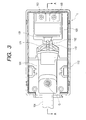
- EP1197389A2 EP1197389A2 EP01308704A EP01308704A EP1197389A2 EP 1197389 A2 EP1197389 A2 EP 1197389A2 EP 01308704 A EP01308704 A EP 01308704A EP 01308704 A EP01308704 A EP 01308704A EP 1197389 A2 EP1197389 A2 EP 1197389A2
- Authority
- EP
- European Patent Office
- Prior art keywords
- winker lever
- winker
- lever
- canceling apparatus
- outer casing
- Prior art date
- Legal status (The legal status is an assumption and is not a legal conclusion. Google has not performed a legal analysis and makes no representation as to the accuracy of the status listed.)
- Withdrawn
Links
- 230000007935 neutral effect Effects 0.000 claims abstract description 24
- 238000001514 detection method Methods 0.000 claims abstract description 8
- 230000007423 decrease Effects 0.000 description 8
- 239000000470 constituent Substances 0.000 description 4
- 230000002159 abnormal effect Effects 0.000 description 3
- 230000007774 longterm Effects 0.000 description 3
- 230000004397 blinking Effects 0.000 description 1
Images


Classifications
-
- B—PERFORMING OPERATIONS; TRANSPORTING
- B60—VEHICLES IN GENERAL
- B60Q—ARRANGEMENT OF SIGNALLING OR LIGHTING DEVICES, THE MOUNTING OR SUPPORTING THEREOF OR CIRCUITS THEREFOR, FOR VEHICLES IN GENERAL
- B60Q1/00—Arrangement of optical signalling or lighting devices, the mounting or supporting thereof or circuits therefor
- B60Q1/26—Arrangement of optical signalling or lighting devices, the mounting or supporting thereof or circuits therefor the devices being primarily intended to indicate the vehicle, or parts thereof, or to give signals, to other traffic
- B60Q1/34—Arrangement of optical signalling or lighting devices, the mounting or supporting thereof or circuits therefor the devices being primarily intended to indicate the vehicle, or parts thereof, or to give signals, to other traffic for indicating change of drive direction
- B60Q1/40—Arrangement of optical signalling or lighting devices, the mounting or supporting thereof or circuits therefor the devices being primarily intended to indicate the vehicle, or parts thereof, or to give signals, to other traffic for indicating change of drive direction having mechanical, electric or electronic automatic return to inoperative position
- B60Q1/42—Arrangement of optical signalling or lighting devices, the mounting or supporting thereof or circuits therefor the devices being primarily intended to indicate the vehicle, or parts thereof, or to give signals, to other traffic for indicating change of drive direction having mechanical, electric or electronic automatic return to inoperative position having mechanical automatic return to inoperative position due to steering-wheel position, e.g. with roller wheel control
- B60Q1/425—Arrangement of optical signalling or lighting devices, the mounting or supporting thereof or circuits therefor the devices being primarily intended to indicate the vehicle, or parts thereof, or to give signals, to other traffic for indicating change of drive direction having mechanical, electric or electronic automatic return to inoperative position having mechanical automatic return to inoperative position due to steering-wheel position, e.g. with roller wheel control using a latching element for resetting a switching element
-
- B—PERFORMING OPERATIONS; TRANSPORTING
- B60—VEHICLES IN GENERAL
- B60Q—ARRANGEMENT OF SIGNALLING OR LIGHTING DEVICES, THE MOUNTING OR SUPPORTING THEREOF OR CIRCUITS THEREFOR, FOR VEHICLES IN GENERAL
- B60Q1/00—Arrangement of optical signalling or lighting devices, the mounting or supporting thereof or circuits therefor
- B60Q1/26—Arrangement of optical signalling or lighting devices, the mounting or supporting thereof or circuits therefor the devices being primarily intended to indicate the vehicle, or parts thereof, or to give signals, to other traffic
- B60Q1/34—Arrangement of optical signalling or lighting devices, the mounting or supporting thereof or circuits therefor the devices being primarily intended to indicate the vehicle, or parts thereof, or to give signals, to other traffic for indicating change of drive direction
- B60Q1/40—Arrangement of optical signalling or lighting devices, the mounting or supporting thereof or circuits therefor the devices being primarily intended to indicate the vehicle, or parts thereof, or to give signals, to other traffic for indicating change of drive direction having mechanical, electric or electronic automatic return to inoperative position
Definitions
- the present invention relates to a canceling apparatus for a winker lever of an automobile.
- FIGS. 7A and 7B are views each illustrating an operation of the related canceling apparatus for a winker lever. These figures are drawn by supposing that the related winker lever cancellation apparatus is seen from above in a state in which an under cover is removed therefrom.
- FIG. 7A shows a neutral (or turned-off) state of this winker lever, while FIG. 7B shows a turned-on state thereof.
- This related canceling apparatus for a winker lever is adapted so that a winker lever operation is performed so as to cause a right winker to blink, and that a winker lever is mechanically returned to a neutral position in response to a predetermined steering operation.
- This related apparatus is comprises a spindle portion 901, a back plate 902, a cancel pin 903, a spring 904, and a cancel cam 905.
- reference numeral 900 designates an under cover. Further, an outer casing of this related apparatus is constructed by attaching an upper cover (not shown in these figure) to this under cover 900.
- a lever 906 is turned in a direction of an arrow D shown in FIG. 7A and then the cancel pin 903 projects in the direction of an arrow E shown in FIG. 7B.
- the right winker blinks according to the turn of the lever 906.
- the lever 906 turns in a direction opposite to the aforementioned direction of the turn thereof. Further, the apparatus performs a similar operation. Thus, a left winker blinks.
- FIGS . 8A and 8B are views for comparing a normal condition operation of a related canceling apparatus for a winker lever with an abnormal condition operation thereof. Particularly, FIG. 8A illustrates an operation to be performed in the normal condition of the related canceling apparatus for a winker lever. FIG. 8B illustrates an operation to be performed in the abnormal condition thereof. The problem is described hereinafter by comparing theses figures with each other. Incidentally, in FIGS. 8A and 8B, only necessary ones of constituent elements are selected and described for brevity of description. Further, in FIGS. 8A and 8B, like reference numerals designate like constituent elements shown in FIG. 7.
- the lap amount L1 between the cancel pin 903 and the cancel cam 905 is 3.0 mm when the apparatus is in a turned-on state under a normal condition.
- the cancel cam 905 turns in a clockwise direction in response to a steering operation as indicated by an arrow X
- the cancel pin 903 turns around a rotation center shaft 933 in a direction designated by reference character Y.
- the rotation of the cancel pin 903 is finally controlled as indicated by one-dot chain lines.
- the cancel pin 903 performs the turn, the abutting portion of the cancel pin 903 is pushed as described above. Consequently, the winker lever 906 connected to the back plate 902 is returned to the neutral state.
- a rotation angle ⁇ 1 of the canceling pin 903 under this normal condition is 41.2 degrees, as shown in this figure.
- the lap amount between the cancel pin 903 and the cancel cam 905 decreases.
- the rotation range ⁇ 2 of the cancel pin 903 decreases to 35.8 degrees.
- the lap amount decreases still more and the rotation range of the cancel pin 903 decreases still more.
- the rotation range ⁇ 3 of the cancel pin 903 decreases to 29.2 degrees.
- an object of the invention is to provide a canceling apparatus for a winker lever, which is enabled to prevent an occurrence of an error in performing a turn canceling operation of a winker lever.
- the invention is characterized by having the following arrangement.
- the angle sensor detects the rotation angle by turning on or off the phototransistor.
- the angle sensor of a simple structure reliably detects the rotation angle. That is, basically, the angle sensor is simply constructed only by the photointerrupter 54 and the phototransistor. Moreover, there is no electrical contact between the disk and the photointerrupter. Thus, an electrical contact failure due to electrical contact wear does not occur. Consequently, the rotation angle is reliably detected in a long term.
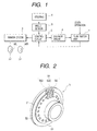
- FIG. 1 is ablock view illustrating an example of a canceling apparatus for a winker lever, which embodies the invention. This example is assumed to be a canceling apparatus for a winker lever of an automobile.
- a turn switch unit 1 supplies a right-turn indication signal or a left-turn indication signal to a control circuit 2 in response to a winker lever operation, that is, a lever operation for indicating a right turn or a left turn by using a winker. Further, in response to the lever operation, the turn switch unit 1 causes an operating plate of a solenoid incorporated in the unit to move.
- the control circuit 2 controls a winker driver 3 in response to this right-turn or left-turn indication signal so as to cause a right winker or a left winker to blink.
- the winker driver 3 supplies a blinking signal, whose frequency is 60 to 120 Hz, to the right winker WR or the left winker WL under the control of a well-known intermittent switching device including a flasher relay.
- an angle sensor 5 detects a rotation angle of a steering 4 and then generates pulses according to the detected rotation angle. Further, the angle sensor 5 supplies the pulses to the control circuit 2.
- This angle sensor 5 is obtained by utilizing a photointerrupter, and described later with reference to FIG. 2.
- the control circuit 2 performs arithmetic processing on the pulses outputted from the angle sensor 5 and calculates a rotation angle of the steering 4.
- a solenoid driver 6 is activated to return the winker lever to the neutral position.
- This solenoid driver 6 comprises, for instance, a solenoid relay.
- the solenoid When the solenoid is controlled and driven by the solenoid driver 6, the solenoid attracts the operating plate moved in response to the lever operation, as described above. As this attracting operation is performed, the solenoid returns the winker lever to the neutral position.
- FIG. 2 is a perspective view illustrating an example of an angle sensor for use in the canceling apparatus for a winker lever of this embodiment shown in FIG. 1.
- the angle sensor 5 shown in FIG. 2 is mounted in a combination switch portion of the automobile and operative to detect the steering amount and direction of the steering, that is, the rotation angle thereof.
- the angle sensor 5 has a disk 52 adapted to rotate as the steering operation is performed.
- a plurality of slits 51 and a cutout portion 53 are provided in this disk 52.
- this angle sensor 5 has three sets of photointerrupters 54 (SS1, SS2, and SSC). A phototransistor thereof is turned on or off by interrupting light by the use of the slits 51 and the cutout portion 53 provided in the disk 52. Thus, the rotation angle is detected. That is, a result of turning on or off the phototransistor is obtained by using the slits 51, the cutout 53 and the three sets of photointerrupters SS1, SS2 and SSC, and a three-phase voltage waveform is obtained from the result. Then a signal having this voltage waveform is outputted as a rotation angle signal representing a steering angle.
- SS1, SS2, and SSC three sets of photointerrupters 54
- the angle sensor 5 is adapted to detect the rotation angle by turning on or off the phototransistor.
- the angle sensor 5 has a simple structure reliably and is able to detect a rotation angle. That is, the angle sensor 5 is constructed only by comprising the photointerrupter 54 and the phototransistor in addition to the disk 52, which interlocks with the steering 4, in such a manner as to have a simple structure. Further, there is no electrical contact between the disk 52 and the photointerrupter 54. Thus, an electrical contact failure due to electrical contact wear does not occur. Consequently, the rotation angle is reliably detected in a long term.
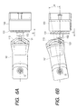
- FIG. 3 is a plan view of the canceling apparatus for a winker lever according to the embodiment. Incidentally, for ready understanding the internal structure of this apparatus, this plan view illustrates a state in which an upper cover is removed from this apparatus.
- FIG. 4 is a sectional view taken on line A-A of FIG. 3, which illustrates the canceling apparatus for a winker lever in the case that the upper cover is attached thereto.
- this canceling apparatus for a winker lever comprises a spindle portion 101, a guide pin 102, a solenoid 103, a winker lever 104, a housing 105, aboard 106, an upper cover 107, amoderationpin 108, amoderation spring 109, a contact slider 110, a moving contact 111, an under cover 112, and a bracket 122.
- the upper cover 107 and the under cover 112 constitute an outer casing of this canceling apparatus for a winker lever.
- the spindle portion 101 for accommodating the winker lever is turnably held through a rotation shaft 120 and a bearing portion 221.
- the solenoid 103 is provided in the outer casing and excited according to the rotation angle signal which is outputted from the angle sensor 5 and represents the steering angle of the steering 4, and serves to act on the winker lever 104 through the spindle portion 101 and to return the winker lever 104 to the neutral position.
- a moderation pin 108 is elastically attached to an end portion of the winker lever 104 through the moderation spring 109. Moreover, a moderation ridge portion 151 is formed in such away as to be integral with the outer casing. The moderation ridge portion 131 is adapted to be engaged with the moderation pin 108 to thereby hold the winker lever 104 in the neutral, left or right position.
- the apparatus has the moving contact 111 which is provided on the electric board 106 accommodated in the outer casing, and the contact slider 110 which interlocks with the winker lever 104 and slides while the slider 110 is in contact with the moving contact 111, as a position detecting portion in appended claims for detecting which of the neutral, left and right positions is a current position in which the winker lever 104 is held.
- the contact slider 110 interlocks with the winker lever 104 and slides while the slider 110 is in contact with the moving contact 111 in this manner. Consequently, the position of the winker lever 104 is detected in response to the operation of the winker lever 104.
- an arcuate guide groove 113 having a predetermined width is integrally formed in the spindle portion 101 as a guide portion in appended claims, which interlocks with the winker lever 104 and guides the winker lever 104 in such a manner as to move to the neutral, left and right positions .
- the arcuate groove 113 has a predetermined width, engages with a projection portion 121 and enables the projection portion 121 to smoothly and reliably slide on the groove 113.
- the projection portion 121 interlocks with an operating plate 131 of the solenoid 103.
- the groove 113 interlocks with the winker lever 104.
- a turn canceling operation of the winker lever 104 is reliably achieved.
- the projection portion 121 for transmitting a driving force of the solenoid 103 and for acting upon the guide groove 113 thereby to control the position of the winker lever 104 is provided on the guide pin 102, which is fixed to the operating plate 131 of the solenoid 103. Additionally, the solenoid 103 is fixed to the board 106 through the bracket 122 by screws 160.
- FIG. 5 is an explanation drawing illustrating a part of each of the lever and the spindle portion, which are shown in FIG. 3, for describing an operation to be performed as the lever moves.
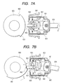
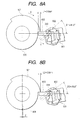
- FIGS. 6A and 6B are explanation drawings illustrating operations performed between the spindle portion and the operating plate of the solenoid, which are shown in FIG. 3.
- FIG. 6A illustrates a neutral state (or turned-off state)
- FIG. 6B illustrates a turned-on state.
- the spindle portion 101 turns by an angle ⁇ .
- the lever 104 turns around an axis of rotation G by an angle ⁇ .
- the moderate pin 108 slides on the moderate ridge portion 151 of the housing 105 and is latched.
- the contact slider 110 which holds the moving contact 111 shown in FIG. 4, moves.
- a turn contact is put into a turned-on state.
- the right-turn indication signal or the left-turn indication signal is outputted to the control circuit 2.
- the spindle portion 101 interlocks with the winker lever 4 and turns around the axis ofrotationGbyanangle ⁇ , as illustrated in FIG . 6B.
- the projection portion 121 of the guide pin 102 moves along the arcuate guide groove 113, which is provided in this spindle portion 101 and has a predetermined width, in the direction of an arrow C shown in this figure.
- the operating plate 131 of the solenoid 103 similarly moves as the projection portion 121 moves.
- the solenoid driver 6 is driven by the control circuit 2 so as to return the winker lever to the neutral position when the steering 4 is turned counterclockwise (or clockwise) by an angle of 20 degrees after clockwise (or counterclockwise) turned more than an angle of 70 degrees, as described above with reference to FIG. 1.
- electric current is fed to the solenoid 103.
- the operating plate 131 of the solenoid 103 is attracted by an electromagnetic force thereof in the direction of an arrow B shown in FIG. 6A.
- the projection portion 121 of the guide pin 102 moves in the direction of the arrow B as the operating plate 131 is attracted. Consequently, the spindle portion 101 is returned to the neutral state shown in FIG. 6A.
- the turn canceling operation of the winker lever is performed.
- the position of the operated winker lever 104 is held by the moderation pin 108 and the moderation ridge portion 151. Further, the position where the winker lever 104 is held is detected by utilizing the contact slider 110 and the moving contact 111. Furthermore, the projection portion 121 and the guide groove 113 respectively interlocking with the operating plate 131 of the solenoid 103 and the winker lever 104 are engaged with each other. Thus, as the excited operating plate 131 moves, the winker lever 104 is returned to the neutral position.
- the moderation pin 108, the moderation ridge portion 151, the contact slider 110, the moving contact 111, the projection portion 121, and the guide groove 113 are accommodated in the canceling apparatus for a winker lever.
- a canceling mechanism is completed in this apparatus. This eliminates the influence of external parts, such as the cancel cam, which affect the related canceling apparatus of the mechanical type for a winker lever. Therefore, there are no errors in performing a turn canceling operation of the winker lever. Furthermore, the external parts, such as the cancel cam, become unnecessary. Consequently, the number of constituent parts is reduced. Moreover, the reliability of the apparatus is enhanced.
- the canceling mechanism is completed in this canceling apparatus for a winker.
- the external parts, such as the cancel cam become unnecessary. Consequently, thenumber of constituent parts is reduced.
- the reliability of the apparatus is enhanced.
- the position detection portion comprises the moving contact 111 and the contact slider 110.
- the contact slider 110 interlocks with the winker lever 104 and slides while the slider 110 is in contact with the moving contact 111.
- the position of the winker lever 104 is reliably detected in response to the operation of the winker lever 104.
- the guide portion is constituted by an arcuate groove 113 having a predetermined width.
- the projection portion 121 smoothly and reliably slides on this groove 113.
- the projection portion 121 interlocks with the operating plate 131 of the solenoid 103, while the groove 113 interlocks with the winker lever 104. Consequently, a turn canceling operation of the winker lever 104 is reliably achieved.
- the angle sensor 5 detects the rotation angle by turning on or off the phototransistor.
- the angle sensor of a simple structure reliably detects the rotation angle. That is, basically, the angle sensor is simply constructed only by the photointerrupter 54 and the phototransistor. Moreover, there is no electrical contact between the disk 52 and the photointerrupter 54. Thus, an electrical contact failure due to electrical contact wear does not occur. Consequently, the rotation angle is reliably detected in a long term. Consequently, a turn canceling operation is stably performed.
Landscapes
- Engineering & Computer Science (AREA)
- Mechanical Engineering (AREA)
- Lighting Device Outwards From Vehicle And Optical Signal (AREA)
- Steering Controls (AREA)
- Mechanisms For Operating Contacts (AREA)
Abstract
Description
- The present invention relates to a canceling apparatus for a winker lever of an automobile.
- Most of related winker lever operation cancellation apparatus of such a kind each include a cancel cam. Such related canceling apparatus for a winker lever have encountered the problem that the position-shift and eccentricity of this cancel cam cause errors in performing a turn canceling operation of a winker lever. This problem is described hereinafter with reference to the accompanying drawings.
- FIGS. 7A and 7B are views each illustrating an operation of the related canceling apparatus for a winker lever. These figures are drawn by supposing that the related winker lever cancellation apparatus is seen from above in a state in which an under cover is removed therefrom. FIG. 7A shows a neutral (or turned-off) state of this winker lever, while FIG. 7B shows a turned-on state thereof.
- This related canceling apparatus for a winker lever is adapted so that a winker lever operation is performed so as to cause a right winker to blink, and that a winker lever is mechanically returned to a neutral position in response to a predetermined steering operation. This related apparatus is comprises a
spindle portion 901, aback plate 902, acancel pin 903, aspring 904, and acancel cam 905. Incidentally,reference numeral 900 designates an under cover. Further, an outer casing of this related apparatus is constructed by attaching an upper cover (not shown in these figure) to this undercover 900. - For example, in case of designating a right turn in a neutral state, a
lever 906 is turned in a direction of an arrow D shown in FIG. 7A and then the cancelpin 903 projects in the direction of an arrow E shown in FIG. 7B. Incidentally, the right winker blinks according to the turn of thelever 906. In case of designating a left turn, thelever 906 turns in a direction opposite to the aforementioned direction of the turn thereof. Further, the apparatus performs a similar operation. Thus, a left winker blinks. - In a state as illustrated in FIG. 7B, when the
cancel cam 905 interlocking with a steering is counterclockwise turned as indicated by an arrow F, anend part 952 of a fan-like portion 951 of thecancel cam 905 abuts against aside wall 931 of thecancel pin 903. Then, when the steering is turned still more, thecancel pin 903 is turned around arotation center shaft 933 so that an abutting portion thereof which abuts against theback plate 902 is pushed in the direction of an arrow H in this figure. Consequently, thewinker lever 906 returns to a neutral state as illustrated in FIG. 7A. Thus, a turn canceling operation of the winker lever is performed. - However, in the case of such a related canceling apparatus for a winker lever, as described above, an error occurs in performing a turn canceling operation of a winker lever. This problem is described hereinafter with reference to FIGS. 8A and 8B.
- FIGS . 8A and 8B are views for comparing a normal condition operation of a related canceling apparatus for a winker lever with an abnormal condition operation thereof. Particularly, FIG. 8A illustrates an operation to be performed in the normal condition of the related canceling apparatus for a winker lever. FIG. 8B illustrates an operation to be performed in the abnormal condition thereof. The problem is described hereinafter by comparing theses figures with each other. Incidentally, in FIGS. 8A and 8B, only necessary ones of constituent elements are selected and described for brevity of description. Further, in FIGS. 8A and 8B, like reference numerals designate like constituent elements shown in FIG. 7.
- As shown in FIG. 8A, the lap amount L1 between the
cancel pin 903 and thecancel cam 905 is 3.0 mm when the apparatus is in a turned-on state under a normal condition. In this state, when thecancel cam 905 turns in a clockwise direction in response to a steering operation as indicated by an arrow X, thecancel pin 903 turns around arotation center shaft 933 in a direction designated by reference character Y. Furthermore, as the steering rotates, the rotation of thecancel pin 903 is finally controlled as indicated by one-dot chain lines. As thecancel pin 903 performs the turn, the abutting portion of thecancel pin 903 is pushed as described above. Consequently, thewinker lever 906 connected to theback plate 902 is returned to the neutral state. A rotation angle β1 of thecanceling pin 903 under this normal condition is 41.2 degrees, as shown in this figure. - However, when the position shift or the eccentricity Z of the
cancel cam 905 occurs as illustrated in FIG. 8B, the lap amount between thecancel pin 903 and the cancelcam 905 decreases. For example, when the lap amount L2 decreases to 2.0 mm, the rotation range β2 of thecancel pin 903 decreases to 35.8 degrees. Further, when both the outside dimensions of thecancel cam 905 and the length of thecancel pin 903 vary to small values, the lap amount decreases still more and the rotation range of thecancel pin 903 decreases still more. For instance, when the lap amount L3 decreases to 1.0 mm, the rotation range β3 of the cancelpin 903 decreases to 29.2 degrees. - As described above, the turning operation of the winker lever connected to the
back plate 902 is canceled by a thrust pressure of theback plate 902, which is caused by rotation of thecancel pin 903. Thus, when the rotation range of thecancel pin 903 decreases as described above, an error occurs in performing a turn canceling operation of the winker lever. - Accordingly, in view of the aforementioned present circumstances, an object of the invention is to provide a canceling apparatus for a winker lever, which is enabled to prevent an occurrence of an error in performing a turn canceling operation of a winker lever.
- In order to solve the aforesaid object, the invention is characterized by having the following arrangement.
- (1) A winker lever canceling apparatus includes:
- an outer casing having an upper cover and an under cover;
- a winker lever turnably held in the outer casing;
- a solenoid for returning the winker lever to a neutral portion, which is excited according to a rotation angle signal outputted from an angle sensor and representing a steering angle of a steering and includes an operating plate;
- a moderation pin elastically provided on the winker lever through a moderation spring;
- a moderation ridge portion integrally formed in the outer casing and engaged with the moderation pin for holding the winker lever in one of neutral, left and right positions;
- a position detection portion formed in the outer casing for detecting the position where the winker lever is held;
- a projection portion which interlocks with the operating plate; and
- a guide portion engaged with the projection portion and provided so as to interlock with the winker lever to return the winker lever to the neutral position according to movement of the operating plate. According to the first aspect of the invention, the position of the operated winker lever is held by the moderation pin and the moderation ridge portion. Further, the position detection portion detects which of the positions is a position in which the winker lever is held. Moreover, the projection portion and the guide portion, which respectively interlock with the operating plate of the solenoid and the winker lever, are engaged with each other. Thus, the winker lever is returned to the neutral position as the excited operating plate moves.
- (2) The winker lever canceling apparatus according to (1),
wherein the position detection portion includes:
- a moving contact provided on an electric board accommodated in the outer casing; and
- a contact slider which interlocks with the winker lever and slides while being in contact with the moving contact. According to the second aspect of the invention, the position detection portion comprises the moving contact and the contact slider. Thus, the contact slider interlocks with the winker lever and slides while the slider is in contact with the moving contact. Thus, the position of the winker lever is reliably detected in response to the operation of the winker lever.
- (3) The winker lever canceling apparatus according to (1), wherein the guide portion is constituted by an arcuate groove having a predetermined width. According to the third aspect of the invention, the guide portion is constituted by an arcuate groove having a predetermined width. Thus, the projection portion smoothly and reliably slides on this groove. The projection portion interlocks with the operating plate of the solenoid, while the groove interlocks with the winker lever. Consequently, a turn canceling operation of the winker lever is reliably achieved.
- (4) The winker lever canceling apparatus according to (1),
wherein
the angle sensor includes a disk having slits and a photointerrupter, and phototransistor, and
the slits and the photointerrupter interrupt light from beyond the dist to turn on or off the phototransistor and the angle sensor detects the rotation angle signal of the steering. -
- According to the fourth aspect of the invention, the angle sensor detects the rotation angle by turning on or off the phototransistor. Thus, the angle sensor of a simple structure reliably detects the rotation angle. That is, basically, the angle sensor is simply constructed only by the photointerrupter 54 and the phototransistor. Moreover, there is no electrical contact between the disk and the photointerrupter. Thus, an electrical contact failure due to electrical contact wear does not occur. Consequently, the rotation angle is reliably detected in a long term.
- FIG. 1 is a block view illustrating an example of a canceling apparatus for a winker lever, which embodies the invention.
- FIG. 2 is a perspective view illustrating an example of an angle sensor for use in the canceling apparatus for a winker lever, which embodies the invention.
- FIG. 3 is a plan view illustrating the canceling apparatus for a winker lever, which embodies the invention in the case that an upper cover is removed therefrom.
- FIG. 4 is a sectional view taken on line A-A of FIG. 3, which illustrates the canceling apparatus for a winker lever in the case that an upper cover is attached thereto.
- FIG. 5 is a view illustrating a part of each of the lever and the spindle portion, which are shown in FIG. 3, for describing an operation to be performed as the lever moves.
- FIGS . 6A and 6B are views illustrating operations performed between the spindle portion and the operating plate of the solenoid, which are shown in FIG. 3.
- FIGS. 7A and 7B are views illustrating an operation of a conventional canceling apparatus for a winker lever.
- FIGS. 8A and 8B are views for comparing a normal condition operation of a related canceling apparatus for a winker lever with an abnormal condition operation thereof.
-
- Hereinafter, an embodiment of the invention is described with reference to the accompanying drawings.
- FIG. 1 is ablock view illustrating an example of a canceling apparatus for a winker lever, which embodies the invention. This example is assumed to be a canceling apparatus for a winker lever of an automobile.
- As shown in FIG. 1, a turn switch unit 1 supplies a right-turn indication signal or a left-turn indication signal to a
control circuit 2 in response to a winker lever operation, that is, a lever operation for indicating a right turn or a left turn by using a winker. Further, in response to the lever operation, the turn switch unit 1 causes an operating plate of a solenoid incorporated in the unit to move. - The
control circuit 2 controls a winker driver 3 in response to this right-turn or left-turn indication signal so as to cause a right winker or a left winker to blink. The winker driver 3 supplies a blinking signal, whose frequency is 60 to 120 Hz, to the right winker WR or the left winker WL under the control of a well-known intermittent switching device including a flasher relay. - On the other hand, an
angle sensor 5 detects a rotation angle of asteering 4 and then generates pulses according to the detected rotation angle. Further, theangle sensor 5 supplies the pulses to thecontrol circuit 2. Thisangle sensor 5 is obtained by utilizing a photointerrupter, and described later with reference to FIG. 2. - The
control circuit 2 performs arithmetic processing on the pulses outputted from theangle sensor 5 and calculates a rotation angle of thesteering 4. When the rotation angle of thesteering 4 meets predetermined conditions, for example, when thesteering 4 is counterclockwise (or clockwise) turned by an angle of 20 degrees after clockwise (or counterclockwise) turned more than an angle of 70 degrees, asolenoid driver 6 is activated to return the winker lever to the neutral position. Thissolenoid driver 6 comprises, for instance, a solenoid relay. - When the solenoid is controlled and driven by the
solenoid driver 6, the solenoid attracts the operating plate moved in response to the lever operation, as described above. As this attracting operation is performed, the solenoid returns the winker lever to the neutral position. - FIG. 2 is a perspective view illustrating an example of an angle sensor for use in the canceling apparatus for a winker lever of this embodiment shown in FIG. 1.
- The
angle sensor 5 shown in FIG. 2 is mounted in a combination switch portion of the automobile and operative to detect the steering amount and direction of the steering, that is, the rotation angle thereof. Theangle sensor 5 has adisk 52 adapted to rotate as the steering operation is performed. A plurality ofslits 51 and acutout portion 53 are provided in thisdisk 52. - Moreover, this
angle sensor 5 has three sets of photointerrupters 54 (SS1, SS2, and SSC). A phototransistor thereof is turned on or off by interrupting light by the use of theslits 51 and thecutout portion 53 provided in thedisk 52. Thus, the rotation angle is detected. That is, a result of turning on or off the phototransistor is obtained by using theslits 51, thecutout 53 and the three sets of photointerrupters SS1, SS2 and SSC, and a three-phase voltage waveform is obtained from the result. Then a signal having this voltage waveform is outputted as a rotation angle signal representing a steering angle. - The
angle sensor 5 is adapted to detect the rotation angle by turning on or off the phototransistor. Thus, theangle sensor 5 has a simple structure reliably and is able to detect a rotation angle. That is, theangle sensor 5 is constructed only by comprising thephotointerrupter 54 and the phototransistor in addition to thedisk 52, which interlocks with thesteering 4, in such a manner as to have a simple structure. Further, there is no electrical contact between thedisk 52 and thephotointerrupter 54. Thus, an electrical contact failure due to electrical contact wear does not occur. Consequently, the rotation angle is reliably detected in a long term. - Next, the canceling apparatus for a winker lever according to this embodiment is described hereinafter by referring to FIGS. 3 and 4.
- FIG. 3 is a plan view of the canceling apparatus for a winker lever according to the embodiment. Incidentally, for ready understanding the internal structure of this apparatus, this plan view illustrates a state in which an upper cover is removed from this apparatus. FIG. 4 is a sectional view taken on line A-A of FIG. 3, which illustrates the canceling apparatus for a winker lever in the case that the upper cover is attached thereto.
- As illustrated in these figures, this canceling apparatus for a winker lever comprises a
spindle portion 101, aguide pin 102, asolenoid 103, awinker lever 104, ahousing 105, aboard 106, anupper cover 107,amoderationpin 108,amoderation spring 109, acontact slider 110, a movingcontact 111, an undercover 112, and abracket 122. - The
upper cover 107 and theunder cover 112 constitute an outer casing of this canceling apparatus for a winker lever. In this outer casing, thespindle portion 101 for accommodating the winker lever is turnably held through arotation shaft 120 and a bearingportion 221. - Moreover, the
solenoid 103 is provided in the outer casing and excited according to the rotation angle signal which is outputted from theangle sensor 5 and represents the steering angle of thesteering 4, and serves to act on thewinker lever 104 through thespindle portion 101 and to return thewinker lever 104 to the neutral position. - A
moderation pin 108 is elastically attached to an end portion of thewinker lever 104 through themoderation spring 109. Moreover, amoderation ridge portion 151 is formed in such away as to be integral with the outer casing. Themoderation ridge portion 131 is adapted to be engaged with themoderation pin 108 to thereby hold thewinker lever 104 in the neutral, left or right position. Furthermore, the apparatus has the movingcontact 111 which is provided on theelectric board 106 accommodated in the outer casing, and thecontact slider 110 which interlocks with thewinker lever 104 and slides while theslider 110 is in contact with the movingcontact 111, as a position detecting portion in appended claims for detecting which of the neutral, left and right positions is a current position in which thewinker lever 104 is held. - The
contact slider 110 interlocks with thewinker lever 104 and slides while theslider 110 is in contact with the movingcontact 111 in this manner. Consequently, the position of thewinker lever 104 is detected in response to the operation of thewinker lever 104. - Furthermore, an
arcuate guide groove 113 having a predetermined width is integrally formed in thespindle portion 101 as a guide portion in appended claims, which interlocks with thewinker lever 104 and guides thewinker lever 104 in such a manner as to move to the neutral, left and right positions . - Thus, the
arcuate groove 113 has a predetermined width, engages with aprojection portion 121 and enables theprojection portion 121 to smoothly and reliably slide on thegroove 113. Theprojection portion 121 interlocks with anoperating plate 131 of thesolenoid 103. Thegroove 113 interlocks with thewinker lever 104. Thus, finally, a turn canceling operation of thewinker lever 104 is reliably achieved. - Furthermore, the
projection portion 121 for transmitting a driving force of thesolenoid 103 and for acting upon theguide groove 113 thereby to control the position of thewinker lever 104 is provided on theguide pin 102, which is fixed to theoperating plate 131 of thesolenoid 103. Additionally, thesolenoid 103 is fixed to theboard 106 through thebracket 122 byscrews 160. - Further, an operation of the canceling apparatus for a winker lever according to the invention is described hereinafter. FIG. 5 is an explanation drawing illustrating a part of each of the lever and the spindle portion, which are shown in FIG. 3, for describing an operation to be performed as the lever moves. FIGS. 6A and 6B are explanation drawings illustrating operations performed between the spindle portion and the operating plate of the solenoid, which are shown in FIG. 3. FIG. 6A illustrates a neutral state (or turned-off state), and FIG. 6B illustrates a turned-on state.
- When the
lever 104 is operated so as to indicate the direction of turn of the automobile from the neutral position illustrated in FIG. 6A, that is, to indicate a right turn or a left turn, thespindle portion 101 turns by an angle α. At this time, in thespindle portion 101, thelever 104 turns around an axis of rotation G by an angle α. Then, themoderate pin 108 slides on themoderate ridge portion 151 of thehousing 105 and is latched. Simultaneously with this, thecontact slider 110, which holds the movingcontact 111 shown in FIG. 4, moves. Then, a turn contact is put into a turned-on state. Subsequently, the right-turn indication signal or the left-turn indication signal is outputted to thecontrol circuit 2. - Furthermore, at this time, the
spindle portion 101 interlocks with thewinker lever 4 and turns around the axis ofrotationGbyanangle α, as illustrated in FIG . 6B. Moreover, at this time, theprojection portion 121 of theguide pin 102 moves along thearcuate guide groove 113, which is provided in thisspindle portion 101 and has a predetermined width, in the direction of an arrow C shown in this figure. Theoperating plate 131 of thesolenoid 103 similarly moves as theprojection portion 121 moves. - On the other hand, in the case that a turn canceling operation is performed, the
solenoid driver 6 is driven by thecontrol circuit 2 so as to return the winker lever to the neutral position when thesteering 4 is turned counterclockwise (or clockwise) by an angle of 20 degrees after clockwise (or counterclockwise) turned more than an angle of 70 degrees, as described above with reference to FIG. 1. At this time, electric current is fed to thesolenoid 103. Theoperating plate 131 of thesolenoid 103 is attracted by an electromagnetic force thereof in the direction of an arrow B shown in FIG. 6A. Similarly, theprojection portion 121 of theguide pin 102 moves in the direction of the arrow B as theoperating plate 131 is attracted. Consequently, thespindle portion 101 is returned to the neutral state shown in FIG. 6A. Thus, the turn canceling operation of the winker lever is performed. - As described above, according to this embodiment, the position of the operated
winker lever 104 is held by themoderation pin 108 and themoderation ridge portion 151. Further, the position where thewinker lever 104 is held is detected by utilizing thecontact slider 110 and the movingcontact 111. Furthermore, theprojection portion 121 and theguide groove 113 respectively interlocking with theoperating plate 131 of thesolenoid 103 and thewinker lever 104 are engaged with each other. Thus, as theexcited operating plate 131 moves, thewinker lever 104 is returned to the neutral position. - The
moderation pin 108, themoderation ridge portion 151, thecontact slider 110, the movingcontact 111, theprojection portion 121, and theguide groove 113 are accommodated in the canceling apparatus for a winker lever. A canceling mechanism is completed in this apparatus. This eliminates the influence of external parts, such as the cancel cam, which affect the related canceling apparatus of the mechanical type for a winker lever. Therefore, there are no errors in performing a turn canceling operation of the winker lever. Furthermore, the external parts, such as the cancel cam, become unnecessary. Consequently, the number of constituent parts is reduced. Moreover, the reliability of the apparatus is enhanced. - As described above, according to the invention, the canceling mechanism is completed in this canceling apparatus for a winker. This eliminates the influence of external parts, such as the cancel cam, which affect the conventional canceling apparatus of the mechanical type for a winker lever. Therefore, there are no errors in performing a turn canceling operation of the
winker lever 104. Furthermore, the external parts, such as the cancel cam, become unnecessary. Consequently, thenumber of constituent parts is reduced. Moreover, the reliability of the apparatus is enhanced. - Further, according to the invention, the position detection portion comprises the moving
contact 111 and thecontact slider 110. Thus, thecontact slider 110 interlocks with thewinker lever 104 and slides while theslider 110 is in contact with the movingcontact 111. Thus, the position of thewinker lever 104 is reliably detected in response to the operation of thewinker lever 104. - Further, according to the invention, the guide portion is constituted by an
arcuate groove 113 having a predetermined width. Thus, theprojection portion 121 smoothly and reliably slides on thisgroove 113. Theprojection portion 121 interlocks with theoperating plate 131 of thesolenoid 103, while thegroove 113 interlocks with thewinker lever 104. Consequently, a turn canceling operation of thewinker lever 104 is reliably achieved. - According to the fourth canceling apparatus of the invention, the
angle sensor 5 detects the rotation angle by turning on or off the phototransistor. Thus, the angle sensor of a simple structure reliably detects the rotation angle. That is, basically, the angle sensor is simply constructed only by the photointerrupter 54 and the phototransistor. Moreover, there is no electrical contact between thedisk 52 and thephotointerrupter 54. Thus, an electrical contact failure due to electrical contact wear does not occur. Consequently, the rotation angle is reliably detected in a long term. Consequently, a turn canceling operation is stably performed.
Claims (4)
- A winker lever canceling apparatus comprising:an outer casing having an upper cover and an under cover;a winker lever turnably held in the outer casing;a solenoid for returning the winker lever to a neutral portion, which is excited according to a rotation angle signal outputted from an angle sensor and representing a steering angle of a steering and includes an operating plate;a moderation pin elastically provided on the winker lever through a moderation spring;a moderation ridge portion integrally formed in the outer casing and engaged with the moderation pin for holding the winker lever in one of neutral, left and right positions;a position detection portion formed in the outer casing for detecting the position where the winker lever is held;a projection portion which interlocks with the operating plate; anda guide portion engaged with the projection portion and provided so as to interlock with the winker lever to return the winker lever to the neutral position according to movement of the operating plate.
- The winker lever canceling apparatus according to claim 1, wherein the position detection portion includes:amoving contact provided on an electric board accommodated in the outer casing; anda contact slider which interlocks with the winker lever and slides while being in contact with the moving contact.
- The winker lever canceling apparatus according to claim 1, wherein the guide portion is constituted by an arcuate groove having a predetermined width.
- The winker lever canceling apparatus according to claim 1, wherein
the angle sensor includes a disk having slits and a photointerrupter, and phototransistor, and
the slits and the photointerrupter interrupt light from beyond the dist to turn on or off the phototransistor and the angle sensor detects the rotation angle signal of the steering.
Applications Claiming Priority (2)
| Application Number | Priority Date | Filing Date | Title |
|---|---|---|---|
| JP2000313735A JP2002120645A (en) | 2000-10-13 | 2000-10-13 | Turn signal lever canceling device |
| JP2000313735 | 2000-10-13 |
Publications (2)
| Publication Number | Publication Date |
|---|---|
| EP1197389A2 true EP1197389A2 (en) | 2002-04-17 |
| EP1197389A3 EP1197389A3 (en) | 2003-01-08 |
Family
ID=18793104
Family Applications (1)
| Application Number | Title | Priority Date | Filing Date |
|---|---|---|---|
| EP01308704A Withdrawn EP1197389A3 (en) | 2000-10-13 | 2001-10-12 | Winker lever canceling apparatus |
Country Status (3)
| Country | Link |
|---|---|
| US (1) | US6587045B2 (en) |
| EP (1) | EP1197389A3 (en) |
| JP (1) | JP2002120645A (en) |
Cited By (1)
| Publication number | Priority date | Publication date | Assignee | Title |
|---|---|---|---|---|
| DE102004053520A1 (en) * | 2004-08-26 | 2006-03-02 | Valeo Schalter Und Sensoren Gmbh | Steering column switch |
Families Citing this family (6)
| Publication number | Priority date | Publication date | Assignee | Title |
|---|---|---|---|---|
| US20060044131A1 (en) * | 2004-08-31 | 2006-03-02 | Patel Vipul M | Controlling turn signaling in a vehicle |
| JP4657198B2 (en) * | 2006-12-28 | 2011-03-23 | 東洋電装株式会社 | Turn signal control device for vehicle |
| KR101542257B1 (en) | 2009-04-30 | 2015-08-06 | 대성전기공업 주식회사 | Vehicular lever switching unit |
| DE102011122405A1 (en) * | 2011-12-24 | 2013-06-27 | Valeo Schalter Und Sensoren Gmbh | Steering column switch device for a motor vehicle and motor vehicle with a steering column switch device |
| US9393901B2 (en) * | 2014-07-21 | 2016-07-19 | Kostal Of America | Turn signal systems and methods |
| WO2022248058A1 (en) * | 2021-05-28 | 2022-12-01 | Merit Automotive Electronics Systems S.L.U. | Stalk switch assembly with a controllable releasing mechanism |
Citations (4)
| Publication number | Priority date | Publication date | Assignee | Title |
|---|---|---|---|---|
| US4900946A (en) * | 1988-06-03 | 1990-02-13 | Navistar International Transportation Corp. | Multi-function switch for automotive vehicles |
| DE4009007A1 (en) * | 1989-03-22 | 1990-09-27 | Fuji Heavy Ind Ltd | METHOD FOR DETECTING THE ABSOLUTE STEERING ANGLE OF A STEERING ANGLE SENSOR FOR A VEHICLE |
| DE19525138A1 (en) * | 1994-07-12 | 1996-01-18 | Marquardt Gmbh | Electrical units mounted on steering wheel of road vehicle |
| WO1998026952A1 (en) * | 1996-12-16 | 1998-06-25 | Robert Bosch Gmbh | Vehicle turn indicator system |
Family Cites Families (16)
| Publication number | Priority date | Publication date | Assignee | Title |
|---|---|---|---|---|
| JPS6140043Y2 (en) * | 1979-03-10 | 1986-11-15 | ||
| JPS57201734A (en) * | 1981-06-02 | 1982-12-10 | Honda Motor Co Ltd | Automatically cancelling device of winker |
| JPS5847639A (en) * | 1981-09-16 | 1983-03-19 | Honda Motor Co Ltd | Automatic turn signal canceling device |
| JPS59143913A (en) * | 1983-02-07 | 1984-08-17 | Toyota Motor Corp | Device for detecting center of steering angle of vehicle |
| JPS608134A (en) | 1983-06-27 | 1985-01-17 | Nippon Denso Co Ltd | Automatic winker reset for vehicle |
| JPS6057449U (en) * | 1983-09-28 | 1985-04-22 | アルプス電気株式会社 | Automatic display release device for motorcycle direction indicators |
| US4638290A (en) * | 1985-05-22 | 1987-01-20 | Motorola, Inc. | Electronic turn signal cancellation apparatus |
| JPH01161956A (en) | 1987-12-18 | 1989-06-26 | Canon Inc | communication equipment system |
| JPH01161956U (en) * | 1988-04-28 | 1989-11-10 | ||
| JPH01170043U (en) * | 1988-05-12 | 1989-11-30 | ||
| JPH0344042A (en) | 1989-07-11 | 1991-02-25 | Nec Corp | Resin seal die for semiconductor device |
| JPH0638756Y2 (en) * | 1989-09-09 | 1994-10-12 | アルプス電気株式会社 | Auto Cancellation Device for Turn Signal |
| US5260685A (en) * | 1992-03-20 | 1993-11-09 | Federal-Mogul Corporation | Time-delayed self-cancelling turn signal |
| JPH10223098A (en) | 1997-02-07 | 1998-08-21 | Matsushita Electric Ind Co Ltd | Lever switch for vehicle |
| US6020813A (en) * | 1999-06-09 | 2000-02-01 | Harris; Carl N. | Self-canceling vehicle turn signal with safety reactivation |
| DE10037586C2 (en) * | 2000-08-02 | 2003-06-18 | Valeo Schalter & Sensoren Gmbh | Reset device for a turn signal switch in motor vehicles |
-
2000
- 2000-10-13 JP JP2000313735A patent/JP2002120645A/en not_active Abandoned
-
2001
- 2001-10-12 EP EP01308704A patent/EP1197389A3/en not_active Withdrawn
- 2001-10-15 US US09/975,958 patent/US6587045B2/en not_active Expired - Fee Related
Patent Citations (4)
| Publication number | Priority date | Publication date | Assignee | Title |
|---|---|---|---|---|
| US4900946A (en) * | 1988-06-03 | 1990-02-13 | Navistar International Transportation Corp. | Multi-function switch for automotive vehicles |
| DE4009007A1 (en) * | 1989-03-22 | 1990-09-27 | Fuji Heavy Ind Ltd | METHOD FOR DETECTING THE ABSOLUTE STEERING ANGLE OF A STEERING ANGLE SENSOR FOR A VEHICLE |
| DE19525138A1 (en) * | 1994-07-12 | 1996-01-18 | Marquardt Gmbh | Electrical units mounted on steering wheel of road vehicle |
| WO1998026952A1 (en) * | 1996-12-16 | 1998-06-25 | Robert Bosch Gmbh | Vehicle turn indicator system |
Cited By (1)
| Publication number | Priority date | Publication date | Assignee | Title |
|---|---|---|---|---|
| DE102004053520A1 (en) * | 2004-08-26 | 2006-03-02 | Valeo Schalter Und Sensoren Gmbh | Steering column switch |
Also Published As
| Publication number | Publication date |
|---|---|
| US20020056629A1 (en) | 2002-05-16 |
| US6587045B2 (en) | 2003-07-01 |
| EP1197389A3 (en) | 2003-01-08 |
| JP2002120645A (en) | 2002-04-23 |
Similar Documents
| Publication | Publication Date | Title |
|---|---|---|
| US8350731B2 (en) | Complex-operation input device | |
| EP1102290B1 (en) | Stalk switch having the function of latching control lever in operating position | |
| CN109312846A (en) | shifter assembly | |
| EP1589322B1 (en) | Device for detecting rotation in two directions and shift lever device | |
| US6587045B2 (en) | Winker lever canceling apparatus | |
| US20190145510A1 (en) | Shifter assembly | |
| JP2017167067A (en) | Shifter for vehicle | |
| US20090195338A1 (en) | Contactless switch | |
| EP1961612B1 (en) | Turn signal switch device | |
| JP2018189512A (en) | Magnetic position detector | |
| JP4700632B2 (en) | Multi-directional operation device | |
| JPH08264075A (en) | Multifunction switch | |
| JP2001165607A (en) | Steering roll connector and steering neutral position detector | |
| JP7605683B2 (en) | Lever operation device | |
| JP6836962B2 (en) | Operating device | |
| JP4139317B2 (en) | Vehicle direction indication device | |
| JP4733590B2 (en) | Column shift device | |
| KR100871123B1 (en) | Automotive Multifunction Switch | |
| JP5603280B2 (en) | Stoke switch device | |
| CN111911617B (en) | Shift lever device for vehicle | |
| JP2006044511A (en) | Mirror and angle sensing device | |
| JP2019178637A (en) | Grip opening detection device | |
| JP4629608B2 (en) | Shift device | |
| JP2024024870A (en) | Lens device and imaging device | |
| JP2007085429A (en) | Shift position detector for automatic transmission |
Legal Events
| Date | Code | Title | Description |
|---|---|---|---|
| PUAI | Public reference made under article 153(3) epc to a published international application that has entered the european phase |
Free format text: ORIGINAL CODE: 0009012 |
|
| AK | Designated contracting states |
Kind code of ref document: A2 Designated state(s): AT BE CH CY DE DK ES FI FR GB GR IE IT LI LU MC NL PT SE TR |
|
| AX | Request for extension of the european patent |
Free format text: AL;LT;LV;MK;RO;SI |
|
| PUAL | Search report despatched |
Free format text: ORIGINAL CODE: 0009013 |
|
| AK | Designated contracting states |
Kind code of ref document: A3 Designated state(s): AT BE CH CY DE DK ES FI FR GB GR IE IT LI LU MC NL PT SE TR |
|
| AX | Request for extension of the european patent |
Free format text: AL;LT;LV;MK;RO;SI |
|
| 17P | Request for examination filed |
Effective date: 20030620 |
|
| AKX | Designation fees paid |
Designated state(s): DE FR GB |
|
| 17Q | First examination report despatched |
Effective date: 20061107 |
|
| RAP1 | Party data changed (applicant data changed or rights of an application transferred) |
Owner name: YAZAKI CORPORATION |
|
| STAA | Information on the status of an ep patent application or granted ep patent |
Free format text: STATUS: THE APPLICATION IS DEEMED TO BE WITHDRAWN |
|
| 18D | Application deemed to be withdrawn |
Effective date: 20070320 |