EP1197353A2 - Tire structure - Google Patents
Tire structure Download PDFInfo
- Publication number
- EP1197353A2 EP1197353A2 EP01102822A EP01102822A EP1197353A2 EP 1197353 A2 EP1197353 A2 EP 1197353A2 EP 01102822 A EP01102822 A EP 01102822A EP 01102822 A EP01102822 A EP 01102822A EP 1197353 A2 EP1197353 A2 EP 1197353A2
- Authority
- EP
- European Patent Office
- Prior art keywords
- inner member
- outer tire
- tire
- peripheral edges
- wheel rim
- Prior art date
- Legal status (The legal status is an assumption and is not a legal conclusion. Google has not performed a legal analysis and makes no representation as to the accuracy of the status listed.)
- Granted
Links
Images

Classifications
-
- B—PERFORMING OPERATIONS; TRANSPORTING
- B60—VEHICLES IN GENERAL
- B60C—VEHICLE TYRES; TYRE INFLATION; TYRE CHANGING; CONNECTING VALVES TO INFLATABLE ELASTIC BODIES IN GENERAL; DEVICES OR ARRANGEMENTS RELATED TO TYRES
- B60C5/00—Inflatable pneumatic tyres or inner tubes
- B60C5/12—Inflatable pneumatic tyres or inner tubes without separate inflatable inserts, e.g. tubeless tyres with transverse section open to the rim
-
- B—PERFORMING OPERATIONS; TRANSPORTING
- B60—VEHICLES IN GENERAL
- B60C—VEHICLE TYRES; TYRE INFLATION; TYRE CHANGING; CONNECTING VALVES TO INFLATABLE ELASTIC BODIES IN GENERAL; DEVICES OR ARRANGEMENTS RELATED TO TYRES
- B60C29/00—Arrangements of tyre-inflating valves to tyres or rims; Accessories for tyre-inflating valves, not otherwise provided for
- B60C29/04—Connection to tyres or inner tubes
-
- B—PERFORMING OPERATIONS; TRANSPORTING
- B60—VEHICLES IN GENERAL
- B60C—VEHICLE TYRES; TYRE INFLATION; TYRE CHANGING; CONNECTING VALVES TO INFLATABLE ELASTIC BODIES IN GENERAL; DEVICES OR ARRANGEMENTS RELATED TO TYRES
- B60C5/00—Inflatable pneumatic tyres or inner tubes
-
- B—PERFORMING OPERATIONS; TRANSPORTING
- B60—VEHICLES IN GENERAL
- B60C—VEHICLE TYRES; TYRE INFLATION; TYRE CHANGING; CONNECTING VALVES TO INFLATABLE ELASTIC BODIES IN GENERAL; DEVICES OR ARRANGEMENTS RELATED TO TYRES
- B60C5/00—Inflatable pneumatic tyres or inner tubes
- B60C5/02—Inflatable pneumatic tyres or inner tubes having separate inflatable inserts, e.g. with inner tubes; Means for lubricating, venting, preventing relative movement between tyre and inner tube
-
- B—PERFORMING OPERATIONS; TRANSPORTING
- B60—VEHICLES IN GENERAL
- B60C—VEHICLE TYRES; TYRE INFLATION; TYRE CHANGING; CONNECTING VALVES TO INFLATABLE ELASTIC BODIES IN GENERAL; DEVICES OR ARRANGEMENTS RELATED TO TYRES
- B60C5/00—Inflatable pneumatic tyres or inner tubes
- B60C5/12—Inflatable pneumatic tyres or inner tubes without separate inflatable inserts, e.g. tubeless tyres with transverse section open to the rim
- B60C5/16—Sealing means between beads and rims, e.g. bands
-
- B—PERFORMING OPERATIONS; TRANSPORTING
- B60—VEHICLES IN GENERAL
- B60C—VEHICLE TYRES; TYRE INFLATION; TYRE CHANGING; CONNECTING VALVES TO INFLATABLE ELASTIC BODIES IN GENERAL; DEVICES OR ARRANGEMENTS RELATED TO TYRES
- B60C5/00—Inflatable pneumatic tyres or inner tubes
- B60C5/20—Inflatable pneumatic tyres or inner tubes having multiple separate inflatable chambers
- B60C5/22—Inflatable pneumatic tyres or inner tubes having multiple separate inflatable chambers the chambers being annular
Definitions
- the present invention relates to a tire that needs no inner tube and a valve is connected to an inner member which is connected to an inside of the lip of the tire.
- a conventional tire is shown in Fig. 1 and generally includes an outer tire 10, an inner tube 12 which is snugly connected to an inside of the outer tire 10 by pressure.
- a valve 100 is connected to the inner tube 12 and extends through a hole in the wheel rim 11. Air enters into the inner tube 12 via the valve 100 so that a large pressure is applied to an inside of the inner tube 12 so as to expand the outer tire 10 and a lip portion of the outer tire is engaged with the wheel rim 11. If a sharp object penetrates through the outer tire 10 and the inner tube 12, because the inner tube 12 is so thin so that the inner tube could explode and could hurt people. Furthermore, the manufacturers have to establish two different production lines to produce the inner tube and the outer tire that have different features. The inner tube 12 is difficult to be properly received in the inside of the outer tire 10 when engaging the outer tire 10 with the wheel rim 11.
- the present invention intends to provide a tire structure that has an inner member which is adhered to the inside of the lip of the outer tire and the valve is connected to the inner member so that air pressure is filled between the outer tire and the inner member via the valve. Therefore, the tire needs no inner tube.
- the present invention relates to a tire structure and comprises an outer tire and an inner member having a valve connected to the inner member.
- the outer tire has a lip portion on each of two peripheral edges of the outer tire so as to be engaged with a wheel rim.
- the inner member is located inside of the outer tire and has two peripheral edges which are adhered to an inside of the lip portions.
- a valve is connected to the inner member and communicates with a space defined between the outer tire and the inner member.
- the object of the present invention is to provide a tire structure that has an inner member which is adhered to an inside of the lip portions of the outer tire so that air pressure in the tire forces the inner member to lay on the wheel rim and expands the outer tire.
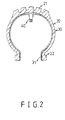
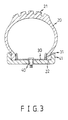
- the tire structure in accordance with the present invention comprises an outer tire 20 having a lip portion 22 on two peripheral edges of the outer tire 20 and the lip portions 22 are to be engaged with a wheel rim 41.
- An inner member 30 is located inside of the outer tire 20 and two peripheral edges 31 of the inner member 30 are adhered to an inside of the lip portions 22.
- the rest portion of the inner member 30 is applied a layer of agent so that the rest portion of the inner member 30 is not adhered to the inside of the outer tire 20.
- a valve 40 is connected to the inner member 30 and communicates with a space defined between the outer tire 20 and the inner member 30. The valve 40 is located at a position where has an equal distance to the two peripheral edges 31 of the inner member 30.
- the tire is a inner-tube-free tire.
Landscapes
- Engineering & Computer Science (AREA)
- Mechanical Engineering (AREA)
- Tires In General (AREA)
- Check Valves (AREA)
Abstract
Description
Claims (2)
- A tire structure comprising:an outer tire having a lip portion on each of two peripheral edges of said outer tire, said lip portions adapted to be engaged with a wheel rim;an inner member located inside of said outer tire and two peripheral edges of said inner member adhered to an inside of said lip portions, anda valve connected to said inner member and communicating with a space defined between said outer tire and said inner member.
- The tire structure as claimed in claim 1, wherein said valve is located at a position where has an equal distance to said two peripheral edges of said inner member.
Applications Claiming Priority (2)
| Application Number | Priority Date | Filing Date | Title |
|---|---|---|---|
| DE20017593U | 2000-10-13 | ||
| DE20017593U DE20017593U1 (en) | 2000-10-13 | 2000-10-13 | Tires for a vehicle |
Publications (3)
| Publication Number | Publication Date |
|---|---|
| EP1197353A2 true EP1197353A2 (en) | 2002-04-17 |
| EP1197353A3 EP1197353A3 (en) | 2003-04-02 |
| EP1197353B1 EP1197353B1 (en) | 2005-07-13 |
Family
ID=7947620
Family Applications (1)
| Application Number | Title | Priority Date | Filing Date |
|---|---|---|---|
| EP01102822A Expired - Lifetime EP1197353B1 (en) | 2000-10-13 | 2001-02-12 | Tire structure |
Country Status (3)
| Country | Link |
|---|---|
| EP (1) | EP1197353B1 (en) |
| AT (1) | ATE299442T1 (en) |
| DE (2) | DE20017593U1 (en) |
Families Citing this family (2)
| Publication number | Priority date | Publication date | Assignee | Title |
|---|---|---|---|---|
| TWM559262U (en) * | 2018-01-12 | 2018-05-01 | 巨大機械工業股份有限公司 | Bicycle and tire structure |
| EP4671002A1 (en) * | 2024-06-28 | 2025-12-31 | REVERSE Components GmbH | Bicycle tires, especially tubeless bicycle tires, and their use, as well as kits of parts comprising the bicycle tire, a bicycle wheel comprising the bicycle tire, and a method for manufacturing the bicycle tire |
Family Cites Families (2)
| Publication number | Priority date | Publication date | Assignee | Title |
|---|---|---|---|---|
| DE1024384B (en) * | 1955-05-07 | 1958-02-13 | Friedrich W Heusinkveld | Tubeless tires, especially for motor vehicles |
| US5109905A (en) * | 1977-12-01 | 1992-05-05 | Lambe Donald M | Dual chamber pneumatic tire with the chambers separated by a collapsible partition wall |
-
2000
- 2000-10-13 DE DE20017593U patent/DE20017593U1/en not_active Expired - Lifetime
-
2001
- 2001-02-12 DE DE60111902T patent/DE60111902T2/en not_active Expired - Fee Related
- 2001-02-12 EP EP01102822A patent/EP1197353B1/en not_active Expired - Lifetime
- 2001-02-12 AT AT01102822T patent/ATE299442T1/en not_active IP Right Cessation
Also Published As
| Publication number | Publication date |
|---|---|
| DE20017593U1 (en) | 2000-12-21 |
| EP1197353B1 (en) | 2005-07-13 |
| DE60111902D1 (en) | 2005-08-18 |
| ATE299442T1 (en) | 2005-07-15 |
| DE60111902T2 (en) | 2006-04-20 |
| EP1197353A3 (en) | 2003-04-02 |
Similar Documents
| Publication | Publication Date | Title |
|---|---|---|
| USD992484S1 (en) | Vehicle wheel rim | |
| USD1031601S1 (en) | Vehicle wheel rim | |
| USD973001S1 (en) | Vehicle wheel rim | |
| USD947740S1 (en) | Vehicle wheel rim | |
| USD1008147S1 (en) | Vehicle wheel rim | |
| USD1054946S1 (en) | Vehicle wheel rim | |
| USD1031582S1 (en) | Vehicle wheel rim | |
| USD1054950S1 (en) | Vehicle wheel rim | |
| USD988961S1 (en) | Automotive wheel | |
| USD972480S1 (en) | Automotive wheel | |
| US20100122758A1 (en) | Tire with foam portion and resilient portion | |
| USD988960S1 (en) | Automotive wheel | |
| CN103429945A (en) | Quick connector | |
| USD1040064S1 (en) | Vehicle wheel rim | |
| US1928836A (en) | Hose coupler | |
| EP1217229A3 (en) | Blind rivet | |
| EP1197353A2 (en) | Tire structure | |
| US6382268B1 (en) | Inflation device | |
| US6470790B1 (en) | Push rod for a brake booster | |
| US20060254349A1 (en) | Method of securing a tire-based unit of a tire condition sensing system to a rim and an associated apparatus | |
| EP1334885A3 (en) | Inflator and closure-fixing structure of the same | |
| US7434891B2 (en) | Structure of a spoke positioning pocket | |
| EP1162089A3 (en) | Vehicle tire air pressure detecting device and cast wheel for mounting the device | |
| USD1090397S1 (en) | Vehicle wheel rim | |
| EP0940269A3 (en) | Tyre system for motorcycles |
Legal Events
| Date | Code | Title | Description |
|---|---|---|---|
| PUAI | Public reference made under article 153(3) epc to a published international application that has entered the european phase |
Free format text: ORIGINAL CODE: 0009012 |
|
| AK | Designated contracting states |
Kind code of ref document: A2 Designated state(s): AT BE CH CY DE DK ES FI FR GB GR IE IT LI LU MC NL PT SE TR |
|
| AX | Request for extension of the european patent |
Free format text: AL;LT;LV;MK;RO;SI |
|
| PUAL | Search report despatched |
Free format text: ORIGINAL CODE: 0009013 |
|
| AK | Designated contracting states |
Kind code of ref document: A3 Designated state(s): AT BE CH CY DE DK ES FI FR GB GR IE IT LI LU MC NL PT SE TR |
|
| AX | Request for extension of the european patent |
Extension state: AL LT LV MK RO SI |
|
| 17P | Request for examination filed |
Effective date: 20030716 |
|
| 17Q | First examination report despatched |
Effective date: 20031002 |
|
| AKX | Designation fees paid |
Designated state(s): AT BE CH CY DE DK ES FI FR GB GR IE IT LI LU MC NL PT SE TR |
|
| GRAP | Despatch of communication of intention to grant a patent |
Free format text: ORIGINAL CODE: EPIDOSNIGR1 |
|
| GRAS | Grant fee paid |
Free format text: ORIGINAL CODE: EPIDOSNIGR3 |
|
| GRAA | (expected) grant |
Free format text: ORIGINAL CODE: 0009210 |
|
| AK | Designated contracting states |
Kind code of ref document: B1 Designated state(s): AT BE CH CY DE DK ES FI FR GB GR IE IT LI LU MC NL PT SE TR |
|
| PG25 | Lapsed in a contracting state [announced via postgrant information from national office to epo] |
Ref country code: IT Free format text: LAPSE BECAUSE OF FAILURE TO SUBMIT A TRANSLATION OF THE DESCRIPTION OR TO PAY THE FEE WITHIN THE PRESCRIBED TIME-LIMIT;WARNING: LAPSES OF ITALIAN PATENTS WITH EFFECTIVE DATE BEFORE 2007 MAY HAVE OCCURRED AT ANY TIME BEFORE 2007. THE CORRECT EFFECTIVE DATE MAY BE DIFFERENT FROM THE ONE RECORDED. Effective date: 20050713 Ref country code: NL Free format text: LAPSE BECAUSE OF FAILURE TO SUBMIT A TRANSLATION OF THE DESCRIPTION OR TO PAY THE FEE WITHIN THE PRESCRIBED TIME-LIMIT Effective date: 20050713 Ref country code: BE Free format text: LAPSE BECAUSE OF FAILURE TO SUBMIT A TRANSLATION OF THE DESCRIPTION OR TO PAY THE FEE WITHIN THE PRESCRIBED TIME-LIMIT Effective date: 20050713 Ref country code: CH Free format text: LAPSE BECAUSE OF FAILURE TO SUBMIT A TRANSLATION OF THE DESCRIPTION OR TO PAY THE FEE WITHIN THE PRESCRIBED TIME-LIMIT Effective date: 20050713 Ref country code: TR Free format text: LAPSE BECAUSE OF FAILURE TO SUBMIT A TRANSLATION OF THE DESCRIPTION OR TO PAY THE FEE WITHIN THE PRESCRIBED TIME-LIMIT Effective date: 20050713 Ref country code: FI Free format text: LAPSE BECAUSE OF FAILURE TO SUBMIT A TRANSLATION OF THE DESCRIPTION OR TO PAY THE FEE WITHIN THE PRESCRIBED TIME-LIMIT Effective date: 20050713 Ref country code: LI Free format text: LAPSE BECAUSE OF FAILURE TO SUBMIT A TRANSLATION OF THE DESCRIPTION OR TO PAY THE FEE WITHIN THE PRESCRIBED TIME-LIMIT Effective date: 20050713 Ref country code: AT Free format text: LAPSE BECAUSE OF FAILURE TO SUBMIT A TRANSLATION OF THE DESCRIPTION OR TO PAY THE FEE WITHIN THE PRESCRIBED TIME-LIMIT Effective date: 20050713 |
|
| REG | Reference to a national code |
Ref country code: GB Ref legal event code: FG4D |
|
| REG | Reference to a national code |
Ref country code: CH Ref legal event code: EP |
|
| REG | Reference to a national code |
Ref country code: IE Ref legal event code: FG4D |
|
| REF | Corresponds to: |
Ref document number: 60111902 Country of ref document: DE Date of ref document: 20050818 Kind code of ref document: P |
|
| PG25 | Lapsed in a contracting state [announced via postgrant information from national office to epo] |
Ref country code: GR Free format text: LAPSE BECAUSE OF FAILURE TO SUBMIT A TRANSLATION OF THE DESCRIPTION OR TO PAY THE FEE WITHIN THE PRESCRIBED TIME-LIMIT Effective date: 20051013 Ref country code: DK Free format text: LAPSE BECAUSE OF FAILURE TO SUBMIT A TRANSLATION OF THE DESCRIPTION OR TO PAY THE FEE WITHIN THE PRESCRIBED TIME-LIMIT Effective date: 20051013 Ref country code: SE Free format text: LAPSE BECAUSE OF FAILURE TO SUBMIT A TRANSLATION OF THE DESCRIPTION OR TO PAY THE FEE WITHIN THE PRESCRIBED TIME-LIMIT Effective date: 20051013 |
|
| PG25 | Lapsed in a contracting state [announced via postgrant information from national office to epo] |
Ref country code: ES Free format text: LAPSE BECAUSE OF FAILURE TO SUBMIT A TRANSLATION OF THE DESCRIPTION OR TO PAY THE FEE WITHIN THE PRESCRIBED TIME-LIMIT Effective date: 20051024 |
|
| PG25 | Lapsed in a contracting state [announced via postgrant information from national office to epo] |
Ref country code: PT Free format text: LAPSE BECAUSE OF FAILURE TO SUBMIT A TRANSLATION OF THE DESCRIPTION OR TO PAY THE FEE WITHIN THE PRESCRIBED TIME-LIMIT Effective date: 20051219 |
|
| REG | Reference to a national code |
Ref country code: FR Ref legal event code: RN |
|
| NLV1 | Nl: lapsed or annulled due to failure to fulfill the requirements of art. 29p and 29m of the patents act | ||
| REG | Reference to a national code |
Ref country code: FR Ref legal event code: FC |
|
| REG | Reference to a national code |
Ref country code: CH Ref legal event code: PL |
|
| PG25 | Lapsed in a contracting state [announced via postgrant information from national office to epo] |
Ref country code: GB Free format text: LAPSE BECAUSE OF NON-PAYMENT OF DUE FEES Effective date: 20060212 |
|
| PG25 | Lapsed in a contracting state [announced via postgrant information from national office to epo] |
Ref country code: IE Free format text: LAPSE BECAUSE OF NON-PAYMENT OF DUE FEES Effective date: 20060213 |
|
| EN | Fr: translation not filed | ||
| PG25 | Lapsed in a contracting state [announced via postgrant information from national office to epo] |
Ref country code: FR Free format text: LAPSE BECAUSE OF FAILURE TO SUBMIT A TRANSLATION OF THE DESCRIPTION OR TO PAY THE FEE WITHIN THE PRESCRIBED TIME-LIMIT Effective date: 20060224 |
|
| PG25 | Lapsed in a contracting state [announced via postgrant information from national office to epo] |
Ref country code: LU Free format text: LAPSE BECAUSE OF NON-PAYMENT OF DUE FEES Effective date: 20060228 Ref country code: MC Free format text: LAPSE BECAUSE OF NON-PAYMENT OF DUE FEES Effective date: 20060228 |
|
| ET | Fr: translation filed | ||
| PLBE | No opposition filed within time limit |
Free format text: ORIGINAL CODE: 0009261 |
|
| STAA | Information on the status of an ep patent application or granted ep patent |
Free format text: STATUS: NO OPPOSITION FILED WITHIN TIME LIMIT |
|
| 26N | No opposition filed |
Effective date: 20060418 |
|
| EN | Fr: translation not filed | ||
| GBPC | Gb: european patent ceased through non-payment of renewal fee |
Effective date: 20060212 |
|
| REG | Reference to a national code |
Ref country code: IE Ref legal event code: MM4A |
|
| PGFP | Annual fee paid to national office [announced via postgrant information from national office to epo] |
Ref country code: DE Payment date: 20080219 Year of fee payment: 8 |
|
| PG25 | Lapsed in a contracting state [announced via postgrant information from national office to epo] |
Ref country code: CY Free format text: LAPSE BECAUSE OF FAILURE TO SUBMIT A TRANSLATION OF THE DESCRIPTION OR TO PAY THE FEE WITHIN THE PRESCRIBED TIME-LIMIT Effective date: 20050713 |
|
| PG25 | Lapsed in a contracting state [announced via postgrant information from national office to epo] |
Ref country code: DE Free format text: LAPSE BECAUSE OF NON-PAYMENT OF DUE FEES Effective date: 20090901 |
|
| REG | Reference to a national code |
Ref country code: FR Ref legal event code: EERR Free format text: CORRECTION DE BOPI 06/08 - 3.2. Ref country code: FR Ref legal event code: EERR Free format text: CORRECTION DE BOPI 06/36 - 3.2. |
|
| REG | Reference to a national code |
Ref country code: FR Ref legal event code: ST Effective date: 20111125 |
|
| PGFP | Annual fee paid to national office [announced via postgrant information from national office to epo] |
Ref country code: FR Payment date: 20111103 Year of fee payment: 10 |
|
| PG25 | Lapsed in a contracting state [announced via postgrant information from national office to epo] |
Ref country code: FR Free format text: LAPSE BECAUSE OF FAILURE TO SUBMIT A TRANSLATION OF THE DESCRIPTION OR TO PAY THE FEE WITHIN THE PRESCRIBED TIME-LIMIT Effective date: 20110228 |