EP1197283A1 - Method for producing and controlling on a fillet gear - Google Patents
Method for producing and controlling on a fillet gear Download PDFInfo
- Publication number
- EP1197283A1 EP1197283A1 EP00121836A EP00121836A EP1197283A1 EP 1197283 A1 EP1197283 A1 EP 1197283A1 EP 00121836 A EP00121836 A EP 00121836A EP 00121836 A EP00121836 A EP 00121836A EP 1197283 A1 EP1197283 A1 EP 1197283A1
- Authority
- EP
- European Patent Office
- Prior art keywords
- fillet
- gear
- set forth
- produced
- curve
- Prior art date
- Legal status (The legal status is an assumption and is not a legal conclusion. Google has not performed a legal analysis and makes no representation as to the accuracy of the status listed.)
- Withdrawn
Links
- 238000004519 manufacturing process Methods 0.000 title claims description 7
- 238000000034 method Methods 0.000 claims abstract description 17
- 238000000227 grinding Methods 0.000 claims description 3
- 238000005520 cutting process Methods 0.000 claims 1
- 238000009826 distribution Methods 0.000 claims 1
- 238000010272 near-net-shape forging Methods 0.000 claims 1
- 238000005452 bending Methods 0.000 description 7
- 238000003801 milling Methods 0.000 description 2
- 238000010586 diagram Methods 0.000 description 1
- 238000004512 die casting Methods 0.000 description 1
- 238000001746 injection moulding Methods 0.000 description 1
- 239000000463 material Substances 0.000 description 1
- 230000013011 mating Effects 0.000 description 1
- 239000000843 powder Substances 0.000 description 1
- 238000005480 shot peening Methods 0.000 description 1
- 230000007704 transition Effects 0.000 description 1
Images
Classifications
-
- B—PERFORMING OPERATIONS; TRANSPORTING
- B23—MACHINE TOOLS; METAL-WORKING NOT OTHERWISE PROVIDED FOR
- B23F—MAKING GEARS OR TOOTHED RACKS
- B23F17/00—Special methods or machines for making gear teeth, not covered by the preceding groups
- B23F17/005—Special methods or machines for making gear teeth, not covered by the preceding groups for machining tooth fillet or tooth root
Definitions
- This invention relates generally to a method for producing a fillet on a gear and controlling the same, and more particularly, to a method for producing a fillet to a shape derived as a function of design criteria for the fillet, and inspecting the fillet for conformance to the derived shape.
- gears In the design of gears, one of the main limiting factors in the load capacity of a given gear is the bending strength of its teeth. Although it is known to increase bending strength by selecting gear teeth having a corser pitch, this has been found to normally reduce the gear's load capacity in other types of failure modes such as pitting and scuffing. Many strategies are known for increasing bending strength of a gear without altering the general gear design, including, but not limited to, use of better materials, hardening methods, and shot peening.
- Another strategy would be to reduce the peak bending stress value of a gear tooth without changing the basic tooth dimensions.
- the typical location for the peak bending stress is the tooth fillet which encompasses a transition area extending between the start of an active profile region of the tooth wherein it engages teeth of a mating gear and the root of the tooth where it joins the gear body.
- An ideal stress reduction strategy would reduce the stress gradient along the tooth fillet such that high stress concentrations are not present.
- the present invention is directed to achieving one or more of the objectives as set forth above.
- a method for producing a fillet on a gear as a function of a plurality of design criteria points includes the steps of fitting a polynomial curve to the design criteria points, and producing the fillet on the gear, the fillet having a curved shape corresponding to the fitted polynomial curve.
- the actual shape of the fillet produced can be inspected and compared to the fitted curve, using a coordinate measuring machine or other suitable device.
- the fillet is produced using a tool having a curved surface corresponding to the polynomial curve.
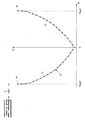
- Fig. 1 is a graph of a plurality of design criteria points 10 for a pair of fillets to extend from the start of the active profile (-X sap ) of a first gear tooth through the root of the tooth (0), to the start of the active profile (X sap ) of an adjacent second gear tooth.
- the locations of points 10 have been determined using an algorithm which provides a relatively flat stress gradient for the fillets, that is, a stress gradient wherein load stresses are substantially evenly distributed along the fillets, such that no substantial stress concentrations are present along the fillet surfaces so as to reduce the likelihood of one or both of the gear teeth breaking in the vicinity of the fillet due to excessive bending stresses.
- a polynomial curve 12, preferably of the second order, is fitted to points 10 as shown using a conventional curve fitting technique, such as the well known least squares technique, using an equation such as the following.
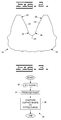
- a segment 14 of a gear 16 is shown including fillets 18 produced according to the present invention.
- Each fillet 18 extends from the start of the active profile 20 or 26 of a respective first gear tooth 22 or an adjacent second gear tooth 28 to the tooth root 24.
- Fillets 18 can be produced using any of a variety of conventional gear manufacturing techniques, including, but not limited to, by milling with a milling cutter, forming with a shape cutter, hobbing, diecasting, drawing, extruding, forming from sintered powder, stamping, or finish grinding of a near net shape which is either machined or forged, preferably to have an outer surface curved to correspond to the desired curved shape leaving a substantially uniform layer of finish stock on the gear.
- Fillets 18 can also be formed by injection molding in the instance of non-metallic gears.
- the curve fitted to the design criteria points is reproduced on the cutter, hob, die, and/or grinding wheel such that the curve is imparted to the fillet when the fillet is produced thereby.
- the curved shape thereof can be compared to the original curve to determine the conformity of the fillet to the curve. This can be accomplished using suitable conventional means, such as, but not limited to, a coordinate measuring machine or the like.
- a flow chart 30 of the present method is shown.
- a polynomial curve is fit to a plurality of design criteria points determined to provide the desired design characteristics for the fillet.
- fillets are produced on a gear between adjacent teeth of the gear, the fillets each having a curved shape corresponding to the polynomial curve fitted at block 32.
- the present method for producing and controlling a gear fillet has utility for use with gears for a wide variety of purposes, particularly wherein design of the fillet to better withstand bending stresses is an important design consideration.
Landscapes
- Engineering & Computer Science (AREA)
- Mechanical Engineering (AREA)
- Gears, Cams (AREA)
Abstract
The present method includes the steps of fitting a polynomial curve
to the design criteria points (10), and producing the fillet (18) on the
gear (16), the fillet having a curved shape corresponding to the fitted
polynomial curve. As a further step for control of the fillet, the
actual shape of the fillet produced can be inspected and compared to the
fitted curve, using a coordinate measuring machine or other suitable
device. According to a further aspect of the invention, the fillet is
produced using a tool having a curved surface corresponding to the
polynomial curve.
Description
- This invention relates generally to a method for producing a fillet on a gear and controlling the same, and more particularly, to a method for producing a fillet to a shape derived as a function of design criteria for the fillet, and inspecting the fillet for conformance to the derived shape.
- In the design of gears, one of the main limiting factors in the load capacity of a given gear is the bending strength of its teeth. Although it is known to increase bending strength by selecting gear teeth having a corser pitch, this has been found to normally reduce the gear's load capacity in other types of failure modes such as pitting and scuffing. Many strategies are known for increasing bending strength of a gear without altering the general gear design, including, but not limited to, use of better materials, hardening methods, and shot peening.
- Another strategy would be to reduce the peak bending stress value of a gear tooth without changing the basic tooth dimensions. In this regard, it is known that the typical location for the peak bending stress is the tooth fillet which encompasses a transition area extending between the start of an active profile region of the tooth wherein it engages teeth of a mating gear and the root of the tooth where it joins the gear body. An ideal stress reduction strategy would reduce the stress gradient along the tooth fillet such that high stress concentrations are not present.
- Accordingly, the present invention is directed to achieving one or more of the objectives as set forth above.
- In one aspect of the present invention, a method for producing a fillet on a gear as a function of a plurality of design criteria points is disclosed. The present method includes the steps of fitting a polynomial curve to the design criteria points, and producing the fillet on the gear, the fillet having a curved shape corresponding to the fitted polynomial curve. As a further step for control of the fillet, the actual shape of the fillet produced can be inspected and compared to the fitted curve, using a coordinate measuring machine or other suitable device. According to a further aspect of the invention, the fillet is produced using a tool having a curved surface corresponding to the polynomial curve.
-
- Fig. 1 is a diagrammatic representation showing a curve fitted to a plurality of design criteria points for a pair of fillets according to the present invention;
- Fig. 2 is a schematic representation of a gear segment including fillets having curved profile shapes produced to the curve of Fig. 1; and
- Fig. 3 is a block diagram of the present method.
-
- Referring now to the drawings, Fig. 1 is a graph of a plurality of
design criteria points 10 for a pair of fillets to extend from the start of the active profile (-Xsap) of a first gear tooth through the root of the tooth (0), to the start of the active profile (Xsap) of an adjacent second gear tooth. The locations ofpoints 10 have been determined using an algorithm which provides a relatively flat stress gradient for the fillets, that is, a stress gradient wherein load stresses are substantially evenly distributed along the fillets, such that no substantial stress concentrations are present along the fillet surfaces so as to reduce the likelihood of one or both of the gear teeth breaking in the vicinity of the fillet due to excessive bending stresses. - A
polynomial curve 12, preferably of the second order, is fitted topoints 10 as shown using a conventional curve fitting technique, such as the well known least squares technique, using an equation such as the following.
- Turning to Fig. 2, a
segment 14 of agear 16 is shown includingfillets 18 produced according to the present invention. Eachfillet 18 extends from the start of theactive profile first gear tooth 22 or an adjacentsecond gear tooth 28 to thetooth root 24. -
Fillets 18 can be produced using any of a variety of conventional gear manufacturing techniques, including, but not limited to, by milling with a milling cutter, forming with a shape cutter, hobbing, diecasting, drawing, extruding, forming from sintered powder, stamping, or finish grinding of a near net shape which is either machined or forged, preferably to have an outer surface curved to correspond to the desired curved shape leaving a substantially uniform layer of finish stock on the gear.Fillets 18 can also be formed by injection molding in the instance of non-metallic gears. Preferably, the curve fitted to the design criteria points is reproduced on the cutter, hob, die, and/or grinding wheel such that the curve is imparted to the fillet when the fillet is produced thereby. - After the fillet has been produced, the curved shape thereof can be compared to the original curve to determine the conformity of the fillet to the curve. This can be accomplished using suitable conventional means, such as, but not limited to, a coordinate measuring machine or the like.
- Turning to Fig. 3, a
flow chart 30 of the present method is shown. Starting atblock 32, a polynomial curve is fit to a plurality of design criteria points determined to provide the desired design characteristics for the fillet. Atblock 34 fillets are produced on a gear between adjacent teeth of the gear, the fillets each having a curved shape corresponding to the polynomial curve fitted atblock 32. - Then, at
block 36 the curve of the fillets produced are compared to the fitted curve for verifying conformance of the curved shaped thereto. - The present method for producing and controlling a gear fillet has utility for use with gears for a wide variety of purposes, particularly wherein design of the fillet to better withstand bending stresses is an important design consideration.
- Other aspects, objects and advantages of the present invention can be obtained from a study of the drawings, the disclosure and the appended claims.
Claims (9)
- A method for producing a fillet 18 on a gear 16 as a function of a plurality of design criteria points 10, the method comprising the steps of:(a) fitting a polynomial curve 12 to the design criteria points 10; and(b) producing the fillet 18 on the gear 16, the fillet 18 having a curved shape corresponding to the polynomial curve 12 fitted in step (a).
- The method, as set forth in claim 1, comprising the further step of comparing the fillet 18 produced in step (b) with the curve 12 fitted in step (a) .
- The method, as set forth in claim 2, wherein the further step is performed using a coordinate measuring machine.
- The method, as set forth in claim 1, comprising the further step of providing a tool having a curved surface corresponding to the polynomial curve 12 fitted in step (a), and wherein the fillet 18 is produced using the tool to impart the curved shape to the fillet 18.
- The method, as set forth in claim 4, wherein the tool is a grinding tool.
- The method, as set forth in claim 4, wherein the tool is a cutting tool.
- The method, as set forth in claim 1, where in step (b) the gear 16 is produced from a near-net shape forging including finish stock for removal when the fillet 18 is produced, the finish stock having an outer surface having a curved shape corresponding to the polynomial curve 12 such that a substantially uniform layer of the finish stock is removed to produce the fillet 18.
- The method, as set forth in claim 1, wherein the polynomial is at least a second order polynomial.
- The method, as set forth in claim 1, wherein the design criteria points 10 have locations determined at least in part using an algorithm for providing a desired distribution of stress along the fillet 18.
Priority Applications (1)
| Application Number | Priority Date | Filing Date | Title |
|---|---|---|---|
| EP00121836A EP1197283A1 (en) | 2000-10-06 | 2000-10-06 | Method for producing and controlling on a fillet gear |
Applications Claiming Priority (1)
| Application Number | Priority Date | Filing Date | Title |
|---|---|---|---|
| EP00121836A EP1197283A1 (en) | 2000-10-06 | 2000-10-06 | Method for producing and controlling on a fillet gear |
Publications (1)
| Publication Number | Publication Date |
|---|---|
| EP1197283A1 true EP1197283A1 (en) | 2002-04-17 |
Family
ID=8170030
Family Applications (1)
| Application Number | Title | Priority Date | Filing Date |
|---|---|---|---|
| EP00121836A Withdrawn EP1197283A1 (en) | 2000-10-06 | 2000-10-06 | Method for producing and controlling on a fillet gear |
Country Status (1)
| Country | Link |
|---|---|
| EP (1) | EP1197283A1 (en) |
Cited By (2)
| Publication number | Priority date | Publication date | Assignee | Title |
|---|---|---|---|---|
| DE102013004861B3 (en) * | 2013-03-21 | 2014-02-27 | Voith Patent Gmbh | Toothing of a gear |
| DE10119050B4 (en) * | 2000-04-19 | 2015-02-05 | Dana Automotive Systems Group, Llc | Straight bevel gears with improved tooth root geometry and method of making a joint for making them |
Citations (7)
| Publication number | Priority date | Publication date | Assignee | Title |
|---|---|---|---|---|
| DE747715C (en) * | 1939-05-28 | 1944-10-11 | Hobbing cutter for creating the undercut on toothed wheels | |
| JPS61117014A (en) * | 1984-11-08 | 1986-06-04 | Toyota Motor Corp | Manufacturing method of highly strengthened gear |
| US4811528A (en) * | 1984-11-03 | 1989-03-14 | Werkzeugmaschinenfabrik Oerlikon-Buhrle Ag | Method for production of envolute gear tooth flanks |
| DE4213927A1 (en) * | 1992-04-28 | 1993-11-04 | Festo Kg | Machine tool computerised control method for milling machine - using interpolation programme with spherical and polynomial functions to interpolate transition lines at connection between trajectory lines |
| DE4305409A1 (en) * | 1993-02-22 | 1994-08-25 | Ibh Bernhard Hilpert Ingenieur | Method for numerical (track) control |
| DE4430003A1 (en) * | 1994-08-25 | 1996-02-29 | Siemens Ag | Numerical displacement control method for automatic machine tool |
| US5802921A (en) * | 1996-08-13 | 1998-09-08 | Rouverol; William S. | Maximum power density gearing |
-
2000
- 2000-10-06 EP EP00121836A patent/EP1197283A1/en not_active Withdrawn
Patent Citations (7)
| Publication number | Priority date | Publication date | Assignee | Title |
|---|---|---|---|---|
| DE747715C (en) * | 1939-05-28 | 1944-10-11 | Hobbing cutter for creating the undercut on toothed wheels | |
| US4811528A (en) * | 1984-11-03 | 1989-03-14 | Werkzeugmaschinenfabrik Oerlikon-Buhrle Ag | Method for production of envolute gear tooth flanks |
| JPS61117014A (en) * | 1984-11-08 | 1986-06-04 | Toyota Motor Corp | Manufacturing method of highly strengthened gear |
| DE4213927A1 (en) * | 1992-04-28 | 1993-11-04 | Festo Kg | Machine tool computerised control method for milling machine - using interpolation programme with spherical and polynomial functions to interpolate transition lines at connection between trajectory lines |
| DE4305409A1 (en) * | 1993-02-22 | 1994-08-25 | Ibh Bernhard Hilpert Ingenieur | Method for numerical (track) control |
| DE4430003A1 (en) * | 1994-08-25 | 1996-02-29 | Siemens Ag | Numerical displacement control method for automatic machine tool |
| US5802921A (en) * | 1996-08-13 | 1998-09-08 | Rouverol; William S. | Maximum power density gearing |
Non-Patent Citations (4)
| Title |
|---|
| CASTELLANI G ET AL: "FILLET GEOMETRY OF GROUND GEAR TEETH", GEAR TECHNOLOGY,US,RANDALL PUBLISHING CO. ELK GROVE, ILLINOIS, vol. 6, no. 1, 1989, pages 19 - 20,22-23,26-, XP000006809, ISSN: 0743-6858 * |
| PAPAIONNOU S G: "MANUFACTURE OF HIGH PRECISION SPUR GEARS WITH END MILLING CUTTERS", TRANSACTIONS OF THE AMERICAN SOCIETY OF MECHANICAL ENGINEERS, SERIES B: JOURNAL OF ENGINEERING FOR INDUSTRY,US,ASME. NEW YORK, vol. 110, no. 4, 1 November 1988 (1988-11-01), pages 359 - 366, XP000024314, ISSN: 0022-0817 * |
| PATENT ABSTRACTS OF JAPAN vol. 010, no. 304 (M - 526) 16 October 1986 (1986-10-16) * |
| SIMON F: "FUENFACHSIGES FRAESEN MIT FERTIGUNGSOPTIMIERENDEM MESSEN AN TURBINENSCHAUFELN", VDI Z,DE,VDI VERLAG GMBH. DUSSELDORF, vol. 133, no. 6, 1 June 1991 (1991-06-01), pages 90 - 92,95-96,, XP000237548, ISSN: 0042-1766 * |
Cited By (2)
| Publication number | Priority date | Publication date | Assignee | Title |
|---|---|---|---|---|
| DE10119050B4 (en) * | 2000-04-19 | 2015-02-05 | Dana Automotive Systems Group, Llc | Straight bevel gears with improved tooth root geometry and method of making a joint for making them |
| DE102013004861B3 (en) * | 2013-03-21 | 2014-02-27 | Voith Patent Gmbh | Toothing of a gear |
Similar Documents
| Publication | Publication Date | Title |
|---|---|---|
| JP5300886B2 (en) | Method of manufacturing a forging die for making sugakasa gears | |
| EP1249641B2 (en) | Bevel gear with modified fillet curve radius | |
| CN88100761A (en) | Manufacturing is used for the method for the ring gear of heavy driving shaft | |
| CN109365731B (en) | Die forging method for high-temperature alloy precision-forged blade | |
| CN88100946A (en) | Method for manufacturing ring gear forging with small allowance | |
| CA2279730C (en) | Method and apparatus for improvement of involute and lead error in powder metal gears | |
| KR20150088688A (en) | Method of manufacturing gear with double teeth patterns involving forging and two stage cold extrusion process | |
| US6164880A (en) | Method for producing and controlling a fillet on a gear | |
| CN101193719B (en) | The blank geometry of engaging tooth | |
| CN102189373A (en) | Integral forging near net shaping process for triple gear block, and prepared gear shaft | |
| CN104159687A (en) | Mechanical structural component, sintered gear, and methods for producing same | |
| US20070125148A1 (en) | Method and apparatus for forging gear teeth | |
| JP5894173B2 (en) | Optimized crowning in bevel gears of bevel gear transmission | |
| CN115270324A (en) | Cold extrusion gear tooth root modeling method | |
| CN100414464C (en) | Modification method of involute straight bevel gear | |
| CN109926533A (en) | A kind of precision plastic forming method of bevel gear | |
| EP1803974B1 (en) | Gear wheel with chamfered portions | |
| CN101193716B (en) | The engaging tooth with the surface compact of special tolerances be made up of agglomerated material | |
| CN112743021B (en) | Blank making method for forging compressor rotor blade | |
| US6626277B2 (en) | Synchronizer sleeve for a change speed gear and method of manufacturing same | |
| EP2896471A1 (en) | Method of manufacturing gear with teeth involving forging | |
| JPS62200071A (en) | Manufacture of high-strength gear | |
| MXPA00009989A (en) | Method for producing and controlling an edge in a gear. | |
| US20010055992A1 (en) | Toothcoupling with face gear toothing | |
| CN104772611A (en) | Forging manufacturing method of gear with teeth |
Legal Events
| Date | Code | Title | Description |
|---|---|---|---|
| PUAI | Public reference made under article 153(3) epc to a published international application that has entered the european phase |
Free format text: ORIGINAL CODE: 0009012 |
|
| AK | Designated contracting states |
Kind code of ref document: A1 Designated state(s): AT BE CH CY DE DK ES FI FR GB GR IE IT LI LU MC NL PT SE |
|
| AX | Request for extension of the european patent |
Free format text: AL;LT;LV;MK;RO;SI |
|
| AKX | Designation fees paid |
Free format text: AT BE CH CY DE DK ES FI FR GB GR IE IT LI LU MC NL PT SE |
|
| STAA | Information on the status of an ep patent application or granted ep patent |
Free format text: STATUS: THE APPLICATION IS DEEMED TO BE WITHDRAWN |
|
| 18D | Application deemed to be withdrawn |
Effective date: 20021018 |