EP1196908B1 - Method and apparatus for allocating channel element resources in communication systems - Google Patents
Method and apparatus for allocating channel element resources in communication systems Download PDFInfo
- Publication number
- EP1196908B1 EP1196908B1 EP00930196A EP00930196A EP1196908B1 EP 1196908 B1 EP1196908 B1 EP 1196908B1 EP 00930196 A EP00930196 A EP 00930196A EP 00930196 A EP00930196 A EP 00930196A EP 1196908 B1 EP1196908 B1 EP 1196908B1
- Authority
- EP
- European Patent Office
- Prior art keywords
- channel elements
- power gain
- forward link
- channel
- link signal
- Prior art date
- Legal status (The legal status is an assumption and is not a legal conclusion. Google has not performed a legal analysis and makes no representation as to the accuracy of the status listed.)
- Expired - Lifetime
Links
- 238000004891 communication Methods 0.000 title claims description 51
- 238000000034 method Methods 0.000 title claims description 9
- 238000012545 processing Methods 0.000 claims description 6
- 238000010586 diagram Methods 0.000 description 3
- 230000000694 effects Effects 0.000 description 3
- 238000001514 detection method Methods 0.000 description 2
- 238000005259 measurement Methods 0.000 description 2
- 230000003321 amplification Effects 0.000 description 1
- 238000006243 chemical reaction Methods 0.000 description 1
- 230000001934 delay Effects 0.000 description 1
- 238000003199 nucleic acid amplification method Methods 0.000 description 1
- 238000013519 translation Methods 0.000 description 1
Images

Classifications
-
- H—ELECTRICITY
- H04—ELECTRIC COMMUNICATION TECHNIQUE
- H04W—WIRELESS COMMUNICATION NETWORKS
- H04W52/00—Power management, e.g. Transmission Power Control [TPC] or power classes
- H04W52/04—Transmission power control [TPC]
- H04W52/30—Transmission power control [TPC] using constraints in the total amount of available transmission power
- H04W52/34—TPC management, i.e. sharing limited amount of power among users or channels or data types, e.g. cell loading
- H04W52/343—TPC management, i.e. sharing limited amount of power among users or channels or data types, e.g. cell loading taking into account loading or congestion level
-
- H—ELECTRICITY
- H04—ELECTRIC COMMUNICATION TECHNIQUE
- H04W—WIRELESS COMMUNICATION NETWORKS
- H04W52/00—Power management, e.g. Transmission Power Control [TPC] or power classes
- H04W52/04—Transmission power control [TPC]
- H04W52/30—Transmission power control [TPC] using constraints in the total amount of available transmission power
- H04W52/34—TPC management, i.e. sharing limited amount of power among users or channels or data types, e.g. cell loading
- H04W52/346—TPC management, i.e. sharing limited amount of power among users or channels or data types, e.g. cell loading distributing total power among users or channels
-
- H—ELECTRICITY
- H04—ELECTRIC COMMUNICATION TECHNIQUE
- H04W—WIRELESS COMMUNICATION NETWORKS
- H04W72/00—Local resource management
- H04W72/04—Wireless resource allocation
Definitions
- the invention generally relates to communication systems, and in particular, to a code division multiple access communication system.
- Hardware or software failure of a communication system has negative effects on the communication system performance. Uninterrupted communication services during a call or standby mode are sought-after attributes of a communication system. Hardware failure in particular would cause long delays in restoring the communication services.
- the communication system 100 may include a number of mobile stations such as mobile stations 101-02, more mobile stations are also possible, but here only two are shown, and a cell site 110 that may be divided into a number of sectors, such as sectors 111-13.
- Each mobile station communicates with the cell site 110, through at least one of the sectors, via a forward wireless link 121 and a reverse wireless link 122.
- Each sector would have associated hardware, such as base transceiver stations (BTS) 114-16.
- BTSs 114-16 are connected to a base station controller (BSC) 117 that controls the operation of the BTSs 114-16, among other functions.
- BSC 117 is connected to other networks or public switching network collectively shown at a block 199.
- WO 9 918 744 A describes a base station architecture.
- each BTS there are a number of hardware elements coupled with controlling software that provide the interface between the mobile stations and the remaining parts of the cell site.
- each BTS has a number of channel elements where each channel element provides hardware and software resources for controlling a communication link.
- Each communication link comprised of a forward link, a link from the BTS to the mobile station, and a reverse link, a link from the mobile station to the BTS.
- a channel element provides functions of the forward link encoding and modulation, data symbols addition (puncturing), and forward power gain adjustment.
- EP 0 887 947 A describes a method for controlling the transmit power of a base station.
- each channel element provides functions of the reverse link demodulation, frame quality determination, and reverse power control.
- a channel element may perform other functions.
- a BTS may have a number of channel elements. Few of the channel elements may not be in use some of the time.
- the communication system 200 includes at least a base transceiver station (BTS), such as BTSs 114-16 shown in FIG. 1.
- BTS base transceiver station
- Each BTS may have a plurality of channel elements, such as channel elements 201-05, representing channel elements 0 through N and N+1 through M.
- the communication system assigns a finite number (N) of channel elements, channel elements 201-03, selected from the plurality of channel elements, 0 through M, 201-05, for services of the forward link.
- the communication system inputs at least one forward link signal 210 associated with the forward link communication to each of the N channel elements 201-203.
- the forward link signal 210 may be generated by a block 290 that encodes forward link voice or data from a public switching network or other sources.
- the communication system determines a power gain requirement of the forward link communication.
- a power control sub-channel is continuously transmitted on the forward link traffic channel.
- the sub-channel transmits at a rate of one bit, at least, every 1.25 mSec.
- a zero bit may indicate to the mobile station to increase the mean power output on the reverse link, and a bit 1 may indicate to decrease the reverse link power level.
- the base station receives and measures signal strength of the reverse link signal transmitted from the mobile station.
- the base station determines the value of the power control bit.
- the mobile station may in a different situation, transmits on the reverse link signal strength measurement of a forward link to the base station.
- the base station may use the mobile assisted signal strength measurement to determine the value of the control bit.
- the power level of the signals and gain obtained from coding of the channels may set the power gain requirements.
- Each channel element has at least a forward link digital gain adjustment block 220.
- the power gain setting of each of the N channel elements 201-03 are adjusted such that an aggregate of power gain settings of the N channel elements 201-03 substantially equals to the determined power gain requirement.
- the N channel elements 201-03 output N forward link signals 231-33 with adjusted power gain accordingly.
- the N forward link signals 231-33 input a forward link digital summer and combiner 240 for combining to form a combined forward link signal 250.
- the combined forward link signal 250 inputs a digital to analog up-conversion block 251 for proper carrier frequency translation and amplification which ultimately transmitted from an analog transmitter 252 to the mobile station.
- the forward signal is minimally effected.
- the effect is reduction in power gain of the combined signal proportional to the power gain contributed by the failed channel element.
- the adjustment of forward power gain may include adjusting power gain setting of each of the N channel elements 201-03 in substantially equal parts such that the aggregate of power gain settings of the N channel elements 201-03 substantially equals to the power gain requirement.
- failure of one channel element has only a factor of 1/N effect in reduction of the amplitude gain.
- Power Gain Reduction 20 log (N-1/N). For example, in case N is equal to 4 and one of the channel elements fails, the power gain reduction is approximately equals to 2.50 dB. The reduction in power gain of approximately 2.5 may be recovered through a power gain adjustment very quickly without interruption of communication services.
- the communication system is a code division multiple access communication system
- the communication system assigns an orthogonal code to the N channel elements 201-03 for coding the input forward link signal 210, at encoder 221 in case of channel element 201, to produce N coded forward link signals 231-33 with adjusted power gain.
- the communication system receives at the N channel elements 201-03 a reverse link signal 260 from the mobile station.
- the reverse link signal 260 is in digital format.
- the signal that was received from the mobile station may be in analog format at an analog radio frequency receiver 280.
- the received signal may be down converted to digital format at 281.
- the communication system selects a first channel element, such as channel element 201, from the N channel elements 201-03 for a processing of the reverse link signal 260.
- the processed signal outputted via output 270 and routed to block 290.
- the communication system detects failure of the first selected channel element 201, the communication system substitutes the processing of the reverse link signal 260 from the first selected channel element 201 to a second channel element, such as channel element 203, selected from the N channel elements excluding the first selected channel element 201.
- a second channel element such as channel element 203
- the reverse communication link would not suffer interruption or termination when the first channel element 201 fails to operate.
- Detection of failure of a channel element may be through detection of failure of a frame quality determination of the reverse link signal at the first or other channel elements of the N channel elements 201-03.
- the communication system determines at 222 power level adjustment of the reverse link signal from the information received from the mobile station.
- the communication system selects a first channel element, such as channel element 201, from the N channel elements 201-03 to add at 223 at least one power level control data bit having a value according to the power level determination to information data transmitted via forward link signal.
- the communication system when detects failure of the selected first channel element substitutes a second channel element selected from the N channel elements excluding the first channel element to add at least the power level control data bit having a value according to the power level determination.
- Each and every portion of the invention may be performed by software, hardware, or a combination of software and hardware. In particular, use of digital signal processor for such implementation is well known in a relevant art.
Landscapes
- Engineering & Computer Science (AREA)
- Computer Networks & Wireless Communication (AREA)
- Signal Processing (AREA)
- Mobile Radio Communication Systems (AREA)
Description
- The invention generally relates to communication systems, and in particular, to a code division multiple access communication system.
- Hardware or software failure of a communication system has negative effects on the communication system performance. Uninterrupted communication services during a call or standby mode are sought-after attributes of a communication system. Hardware failure in particular would cause long delays in restoring the communication services.
- Referring to FIG. 1, a simplified block diagram of a
communication system 100 is shown. Thecommunication system 100 may include a number of mobile stations such as mobile stations 101-02, more mobile stations are also possible, but here only two are shown, and acell site 110 that may be divided into a number of sectors, such as sectors 111-13. Each mobile station communicates with thecell site 110, through at least one of the sectors, via a forwardwireless link 121 and a reversewireless link 122. Each sector would have associated hardware, such as base transceiver stations (BTS) 114-16. The BTSs 114-16 are connected to a base station controller (BSC) 117 that controls the operation of the BTSs 114-16, among other functions. TheBSC 117 is connected to other networks or public switching network collectively shown at ablock 199. - WO 9 918 744 A describes a base station architecture. In each BTS, there are a number of hardware elements coupled with controlling software that provide the interface between the mobile stations and the remaining parts of the cell site. In particular, each BTS has a number of channel elements where each channel element provides hardware and software resources for controlling a communication link. Each communication link comprised of a forward link, a link from the BTS to the mobile station, and a reverse link, a link from the mobile station to the BTS. A channel element provides functions of the forward link encoding and modulation, data symbols addition (puncturing), and forward power gain adjustment. EP 0 887 947 A describes a method for controlling the transmit power of a base station. In addition, each channel element provides functions of the reverse link demodulation, frame quality determination, and reverse power control. A channel element may perform other functions. A BTS may have a number of channel elements. Few of the channel elements may not be in use some of the time. When a channel element fails in the communication system, the communication link that is serviced by the failed channel element is interrupted or terminated even though the link may have been serviced by other channel elements in the BTS.
- Therefore, there is a need for method and apparatus in a communication system for allocating channel elements to a communication link such that failure of one channel element does not terminate or interrupt the communication link.
-
- FIG. 1 depicts a block diagram of a communication system.
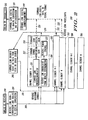
- FIG. 2 depicts detailed block diagram of a communication system according to various aspects of the invention.
-
- Referring to FIG. 2, one or more aspects of the invention are shown in a
communication system 200. Thecommunication system 200 includes at least a base transceiver station (BTS), such as BTSs 114-16 shown in FIG. 1. Each BTS may have a plurality of channel elements, such as channel elements 201-05, representing channel elements 0 through N and N+1 through M. According to the invention, for a forward link communication between a mobile station and a base station, the communication system assigns a finite number (N) of channel elements, channel elements 201-03, selected from the plurality of channel elements, 0 through M, 201-05, for services of the forward link. The communication system inputs at least oneforward link signal 210 associated with the forward link communication to each of the N channel elements 201-203. Theforward link signal 210 may be generated by ablock 290 that encodes forward link voice or data from a public switching network or other sources. - The communication system determines a power gain requirement of the forward link communication. A power control sub-channel is continuously transmitted on the forward link traffic channel. The sub-channel transmits at a rate of one bit, at least, every 1.25 mSec. A zero bit may indicate to the mobile station to increase the mean power output on the reverse link, and a
bit 1 may indicate to decrease the reverse link power level. On the reverse link traffic channel, the base station receives and measures signal strength of the reverse link signal transmitted from the mobile station. The base station then determines the value of the power control bit. The mobile station, may in a different situation, transmits on the reverse link signal strength measurement of a forward link to the base station. The base station may use the mobile assisted signal strength measurement to determine the value of the control bit. In addition, the power level of the signals and gain obtained from coding of the channels may set the power gain requirements. - Each channel element has at least a forward link digital
gain adjustment block 220. The power gain setting of each of the N channel elements 201-03 are adjusted such that an aggregate of power gain settings of the N channel elements 201-03 substantially equals to the determined power gain requirement. The N channel elements 201-03 output N forward link signals 231-33 with adjusted power gain accordingly. - The N forward link signals 231-33 input a forward link digital summer and combiner 240 for combining to form a combined forward link signal 250. The combined forward link signal 250 inputs a digital to analog up-
conversion block 251 for proper carrier frequency translation and amplification which ultimately transmitted from ananalog transmitter 252 to the mobile station. As such, when at least one of the channel elements 201-03 fails for any reason, the forward signal is minimally effected. The effect is reduction in power gain of the combined signal proportional to the power gain contributed by the failed channel element. - The adjustment of forward power gain may include adjusting power gain setting of each of the N channel elements 201-03 in substantially equal parts such that the aggregate of power gain settings of the N channel elements 201-03 substantially equals to the power gain requirement. In this case, failure of one channel element has only a factor of 1/N effect in reduction of the amplitude gain. To translate the power gain reduction one ordinary skilled in the art may find that the reduction in power gain may be governed by the following relationship:
- In case the communication system is a code division multiple access communication system, the communication system assigns an orthogonal code to the N channel elements 201-03 for coding the input
forward link signal 210, atencoder 221 in case ofchannel element 201, to produce N coded forward link signals 231-33 with adjusted power gain. - On the reverse link, the communication system receives at the N channel elements 201-03 a
reverse link signal 260 from the mobile station. Thereverse link signal 260 is in digital format. The signal that was received from the mobile station may be in analog format at an analogradio frequency receiver 280. The received signal may be down converted to digital format at 281. The communication system selects a first channel element, such aschannel element 201, from the N channel elements 201-03 for a processing of thereverse link signal 260. The processed signal outputted viaoutput 270 and routed to block 290. In case the communication system detects failure of the firstselected channel element 201, the communication system substitutes the processing of thereverse link signal 260 from the firstselected channel element 201 to a second channel element, such aschannel element 203, selected from the N channel elements excluding the firstselected channel element 201. As such, the reverse communication link would not suffer interruption or termination when thefirst channel element 201 fails to operate. Detection of failure of a channel element may be through detection of failure of a frame quality determination of the reverse link signal at the first or other channel elements of the N channel elements 201-03. - For reverse power control, the communication system determines at 222 power level adjustment of the reverse link signal from the information received from the mobile station. The communication system selects a first channel element, such as
channel element 201, from the N channel elements 201-03 to add at 223 at least one power level control data bit having a value according to the power level determination to information data transmitted via forward link signal. The communication system when detects failure of the selected first channel element substitutes a second channel element selected from the N channel elements excluding the first channel element to add at least the power level control data bit having a value according to the power level determination. Each and every portion of the invention may be performed by software, hardware, or a combination of software and hardware. In particular, use of digital signal processor for such implementation is well known in a relevant art.
Claims (10)
- A method for communicating between a mobile station and a base station in a communication system that includes said base station having a plurality of channel elements, the method comprising the steps of :assigning a finite number (N) of channel elements selected from said plurality of channel elements for a forward link communication from said base station to said mobile station;inputting at least one forward link signal associated with said forward link communication to each of said N channel elements;determining a power gain requirement of said forward link communication;adjusting power gain setting of each of said N channel elements such that an aggregate of power gain settings of said N channel elements substantially equals to said power gain requirement;outputting N forward link signals with adjusted power gain according to said adjusting step from correspondingly said N channel elements;combining said N forward link signals to form a combined forward link signal.
- The method as recited in claim 1 wherein said adjusting power gain includes adjusting power gain setting of each of said N channel elements in substantially equal parts such that said aggregate of power gain settings of said N channel elements substantially equals to said power gain requirement.
- The method as recited in claim 1, wherein said communication system is a code division multiple access communication system, further comprising the step of:assigning an orthogonal code to said N channel elements for coding said input forward link signal to produce N coded forward link signals with adjusted power gain according to said adjusting step from correspondingly said N channel elements.
- The method as recited in claim 1 further comprising the steps of:receiving at said N channel elements a reverse link signal from said mobile station;selecting a first channel element from said N channel elements for a processing of said reverse link signal.
- The method as recited in claim 4 further comprising the steps of:detecting failure of said first selected channel element;substituting, following said detecting failure, said processing of said reverse link signal from said first selected channel element to a second channel element selected from said N channel elements excluding said first selected channel element.
- An apparatus for communicating between a mobile station and a base station in a communication system that includes a base station having a plurality of channel elements, said apparatus comprising:means for assigning a finite number (N) of channel elements selected from said plurality of channel elements for a forward link communication from said base station to said mobile station;means for inputting at least one forward link signal associated with said forward link communication to each of said N channel elements;means for determining a power gain requirement of said forward link communication;means for adjusting power gain setting of each of said N channel elements such that an aggregate of power gain settings of said N channel elements substantially equals to said power gain requirement;means for outputting N forward link signals with adjusted power gain according to said adjusting step from correspondingly said N channel elements;means for combining said N forward link signals to form a combined forward link signal.
- The apparatus as recited in claim 6 wherein said means for adjusting power gain includes means for adjusting power gain setting of each of said N channel elements in substantially equal parts such that said aggregate of power gain settings of said N channel elements substantially equals to said power gain requirement.
- The apparatus as recited in claim 6, wherein said communication system is a code division multiple access communication system, further comprising:means for assigning an orthogonal code to said N channel elements for coding said input forward link signal to produce N coded forward link signals with adjusted power gain according to said adjusting step from correspondingly said N channel elements.
- The apparatus as recited in claim 6 further comprising:means for receiving at said N channel elements a reverse link signal from said mobile station;means for selecting a first channel element from said N channel elements for a processing of said reverse link signal.
- The apparatus as recited in claim 9 further comprising:means for detecting failure of said first selected channel element;means for substituting, following said detecting failure, said processing of said reverse link signal from said first selected channel element to a second channel element selected from said N channel elements excluding said first selected channel element.
Applications Claiming Priority (3)
| Application Number | Priority Date | Filing Date | Title |
|---|---|---|---|
| US343318 | 1999-06-30 | ||
| US09/343,318 US6144646A (en) | 1999-06-30 | 1999-06-30 | Method and apparatus for allocating channel element resources in communication systems |
| PCT/US2000/011411 WO2001003096A1 (en) | 1999-06-30 | 2000-04-28 | Method and apparatus for allocating channel element resources in communication systems |
Publications (3)
| Publication Number | Publication Date |
|---|---|
| EP1196908A1 EP1196908A1 (en) | 2002-04-17 |
| EP1196908A4 EP1196908A4 (en) | 2002-11-05 |
| EP1196908B1 true EP1196908B1 (en) | 2003-09-17 |
Family
ID=23345601
Family Applications (1)
| Application Number | Title | Priority Date | Filing Date |
|---|---|---|---|
| EP00930196A Expired - Lifetime EP1196908B1 (en) | 1999-06-30 | 2000-04-28 | Method and apparatus for allocating channel element resources in communication systems |
Country Status (5)
| Country | Link |
|---|---|
| US (1) | US6144646A (en) |
| EP (1) | EP1196908B1 (en) |
| DE (1) | DE60005360T2 (en) |
| ES (1) | ES2207515T3 (en) |
| WO (1) | WO2001003096A1 (en) |
Families Citing this family (11)
| Publication number | Priority date | Publication date | Assignee | Title |
|---|---|---|---|---|
| US8605686B2 (en) * | 2001-02-12 | 2013-12-10 | Qualcomm Incorporated | Method and apparatus for power control in a wireless communication system |
| US7688899B2 (en) * | 2001-05-17 | 2010-03-30 | Qualcomm Incorporated | Method and apparatus for processing data for transmission in a multi-channel communication system using selective channel inversion |
| US6751187B2 (en) * | 2001-05-17 | 2004-06-15 | Qualcomm Incorporated | Method and apparatus for processing data for transmission in a multi-channel communication system using selective channel transmission |
| US7072413B2 (en) | 2001-05-17 | 2006-07-04 | Qualcomm, Incorporated | Method and apparatus for processing data for transmission in a multi-channel communication system using selective channel inversion |
| EP1357711A1 (en) * | 2002-04-25 | 2003-10-29 | Alcatel | Method for managing communication services in a communications network, network element and service agreements management centre for its implementation |
| US7212542B2 (en) | 2003-04-08 | 2007-05-01 | Motorola, Inc. | Method and apparatus for maximizing a data rate of a wireless data communication system |
| US7069211B2 (en) * | 2003-04-30 | 2006-06-27 | Motorola, Inc. | Method and apparatus for transferring data over a voice channel |
| US7107037B1 (en) | 2003-05-23 | 2006-09-12 | Sprint Spectrum L.P. | Reserving channel elements to maximize utilization of resources and prevent blocking of calls |
| US7440730B2 (en) * | 2005-06-30 | 2008-10-21 | Intel Corporation | Device, system and method of multiple transceivers control |
| KR101050865B1 (en) * | 2006-08-29 | 2011-07-20 | 후지쯔 가부시끼가이샤 | Communication device, terminal, wireless channel quality management method |
| US9319991B1 (en) * | 2013-03-11 | 2016-04-19 | Sprint Communications Company L.P. | Dynamically adjusting power settings based on a gain mapping file |
Family Cites Families (9)
| Publication number | Priority date | Publication date | Assignee | Title |
|---|---|---|---|---|
| US5724385A (en) * | 1994-09-30 | 1998-03-03 | Qualcomm Incorporated | Serial linked interconnect for summation of multiple waveforms on a common channel |
| JPH08195703A (en) * | 1995-01-17 | 1996-07-30 | Toshiba Corp | Wireless communication device |
| US5893035A (en) * | 1996-09-16 | 1999-04-06 | Qualcomm Incorporated | Centralized forward link power control |
| KR100249643B1 (en) * | 1996-12-28 | 2000-04-01 | 정태기 | Apparatus and method of pseudo frequency for frequency hard handover in cdma mobile communication system |
| US6393005B1 (en) * | 1997-06-27 | 2002-05-21 | Nec Corporation | Method of controlling transmitting power of a base station in a CDMA mobile communication system |
| US6400966B1 (en) * | 1997-10-07 | 2002-06-04 | Telefonaktie Bolaget Lm Ericsson (Publ) | Base station architecture for a mobile communications system |
| US6034971A (en) * | 1998-06-30 | 2000-03-07 | Motorola, Inc. | Method and apparatus for controlling communication system capacity |
| US5991285A (en) * | 1998-08-10 | 1999-11-23 | Motorola, Inc. | Method and apparatus for communicating signals of various channel types in CDMA communication system |
| US7161912B1 (en) * | 1999-10-18 | 2007-01-09 | Lucent Technologies Inc. | Multi-carrier/multi-sector channel pooling in a wireless communication system base station |
-
1999
- 1999-06-30 US US09/343,318 patent/US6144646A/en not_active Expired - Lifetime
-
2000
- 2000-04-28 DE DE60005360T patent/DE60005360T2/en not_active Expired - Lifetime
- 2000-04-28 EP EP00930196A patent/EP1196908B1/en not_active Expired - Lifetime
- 2000-04-28 WO PCT/US2000/011411 patent/WO2001003096A1/en not_active Ceased
- 2000-04-28 ES ES00930196T patent/ES2207515T3/en not_active Expired - Lifetime
Also Published As
| Publication number | Publication date |
|---|---|
| DE60005360D1 (en) | 2003-10-23 |
| ES2207515T3 (en) | 2004-06-01 |
| EP1196908A4 (en) | 2002-11-05 |
| WO2001003096A1 (en) | 2001-01-11 |
| EP1196908A1 (en) | 2002-04-17 |
| US6144646A (en) | 2000-11-07 |
| DE60005360T2 (en) | 2004-04-22 |
Similar Documents
| Publication | Publication Date | Title |
|---|---|---|
| KR100510228B1 (en) | Method and apparatus for implementing diversity for a dual-mode communication unit | |
| US5812935A (en) | Cellular system employing base station transmit diversity according to transmission quality level | |
| CN1027611C (en) | Method and device for establishing a communication link | |
| CN100405753C (en) | Power control subsystem | |
| US6137789A (en) | Mobile station employing selective discontinuous transmission for high speed data services in CDMA multi-channel reverse link configuration | |
| JP4383675B2 (en) | Method and apparatus for controlling variable and fixed rate of forward link in mobile radio communication system | |
| JP2799244B2 (en) | Synchronization method for cellular mobile radio systems | |
| US6775548B1 (en) | Access channel for reduced access delay in a telecommunications system | |
| US6226508B1 (en) | Transmission diversity apparatus | |
| KR20000069867A (en) | Forward link transmission mode for cdma cellular communications system using steerable and distributed antennas | |
| JPH0936801A (en) | Base station transmission power controller | |
| JPH1155180A (en) | Forward traffic channel power control method and apparatus for CDMA wireless subscriber network system | |
| WO2001080575A2 (en) | Cellular communications system/method with uplink interference ceiling | |
| US7069034B1 (en) | Systems and methods for reduced forward link power control delay | |
| US6144646A (en) | Method and apparatus for allocating channel element resources in communication systems | |
| KR100325045B1 (en) | Radio transmission system and transmission method | |
| AU1564100A (en) | Reception method and receiver | |
| JP2954086B2 (en) | Mobile communication system | |
| KR20000005925A (en) | A CDMA mobile communication system and a transmission power control method for the same | |
| US6801785B2 (en) | Transmission power control method in CDMA system | |
| US7583630B2 (en) | Method and system for providing mobile station control of data transmission rates in a wireless network | |
| CN1148917A (en) | Method and apparatus for jump-transmitting digital packet data signals | |
| US20050084027A1 (en) | Method for multiple broadcasting in a mobile radiocommunication system | |
| US6097946A (en) | Method and arrangement for mobile telephony | |
| JPH0795141A (en) | Power control system for multi-channel frequency multiplex signal |
Legal Events
| Date | Code | Title | Description |
|---|---|---|---|
| PUAI | Public reference made under article 153(3) epc to a published international application that has entered the european phase |
Free format text: ORIGINAL CODE: 0009012 |
|
| 17P | Request for examination filed |
Effective date: 20020130 |
|
| AK | Designated contracting states |
Kind code of ref document: A1 Designated state(s): AT BE CH CY DE DK ES FI FR GB GR IE IT LI LU MC NL PT SE Kind code of ref document: A1 Designated state(s): DE ES FI FR GB IT |
|
| A4 | Supplementary search report drawn up and despatched | ||
| AK | Designated contracting states |
Kind code of ref document: A4 Designated state(s): AT BE CH CY DE DK ES FI FR GB GR IE IT LI LU MC NL PT SE |
|
| A4 | Supplementary search report drawn up and despatched |
Effective date: 20021105 |
|
| RIC1 | Information provided on ipc code assigned before grant |
Free format text: 7G 08C 17/00 A, 7H 04B 7/216 B, 7H 04Q 7/30 B, 7H 04B 7/005 B |
|
| GRAH | Despatch of communication of intention to grant a patent |
Free format text: ORIGINAL CODE: EPIDOS IGRA |
|
| GRAS | Grant fee paid |
Free format text: ORIGINAL CODE: EPIDOSNIGR3 |
|
| GRAA | (expected) grant |
Free format text: ORIGINAL CODE: 0009210 |
|
| AK | Designated contracting states |
Kind code of ref document: B1 Designated state(s): DE ES FI FR GB IT |
|
| REG | Reference to a national code |
Ref country code: GB Ref legal event code: FG4D |
|
| REF | Corresponds to: |
Ref document number: 60005360 Country of ref document: DE Date of ref document: 20031023 Kind code of ref document: P |
|
| REG | Reference to a national code |
Ref country code: IE Ref legal event code: FG4D |
|
| ET | Fr: translation filed | ||
| REG | Reference to a national code |
Ref country code: ES Ref legal event code: FG2A Ref document number: 2207515 Country of ref document: ES Kind code of ref document: T3 |
|
| PLBE | No opposition filed within time limit |
Free format text: ORIGINAL CODE: 0009261 |
|
| STAA | Information on the status of an ep patent application or granted ep patent |
Free format text: STATUS: NO OPPOSITION FILED WITHIN TIME LIMIT |
|
| 26N | No opposition filed |
Effective date: 20040618 |
|
| REG | Reference to a national code |
Ref country code: IE Ref legal event code: MM4A |
|
| REG | Reference to a national code |
Ref country code: GB Ref legal event code: 732E Free format text: REGISTERED BETWEEN 20110127 AND 20110202 |
|
| PG25 | Lapsed in a contracting state [announced via postgrant information from national office to epo] |
Ref country code: IT Free format text: LAPSE BECAUSE OF NON-PAYMENT OF DUE FEES Effective date: 20090428 |
|
| REG | Reference to a national code |
Ref country code: DE Ref legal event code: R081 Ref document number: 60005360 Country of ref document: DE Owner name: MOTOROLA MOBILITY, INC. ( N.D. GES. D. STAATES, US Free format text: FORMER OWNER: MOTOROLA, INC., SCHAUMBURG, US Effective date: 20110324 Ref country code: DE Ref legal event code: R081 Ref document number: 60005360 Country of ref document: DE Owner name: MOTOROLA MOBILITY, INC. ( N.D. GES. D. STAATES, US Free format text: FORMER OWNER: MOTOROLA, INC., SCHAUMBURG, ILL., US Effective date: 20110324 Ref country code: DE Ref legal event code: R081 Ref document number: 60005360 Country of ref document: DE Owner name: GOOGLE TECHNOLOGY HOLDINGS LLC, MOUNTAIN VIEW, US Free format text: FORMER OWNER: MOTOROLA, INC., SCHAUMBURG, ILL., US Effective date: 20110324 |
|
| REG | Reference to a national code |
Ref country code: FR Ref legal event code: TP Owner name: MOTOROLA MOBILITY, INC., US Effective date: 20110912 |
|
| REG | Reference to a national code |
Ref country code: FR Ref legal event code: PLFP Year of fee payment: 17 |
|
| REG | Reference to a national code |
Ref country code: FR Ref legal event code: PLFP Year of fee payment: 18 |
|
| PGFP | Annual fee paid to national office [announced via postgrant information from national office to epo] |
Ref country code: FR Payment date: 20170426 Year of fee payment: 18 Ref country code: GB Payment date: 20170427 Year of fee payment: 18 Ref country code: DE Payment date: 20170427 Year of fee payment: 18 |
|
| PGFP | Annual fee paid to national office [announced via postgrant information from national office to epo] |
Ref country code: IT Payment date: 20170421 Year of fee payment: 18 Ref country code: ES Payment date: 20170503 Year of fee payment: 18 Ref country code: FI Payment date: 20170427 Year of fee payment: 18 |
|
| REG | Reference to a national code |
Ref country code: GB Ref legal event code: 732E Free format text: REGISTERED BETWEEN 20170831 AND 20170906 |
|
| REG | Reference to a national code |
Ref country code: FR Ref legal event code: CD Owner name: GOOGLE TECHNOLOGY HOLDINGS LLC, US Effective date: 20171214 Ref country code: FR Ref legal event code: TP Owner name: GOOGLE TECHNOLOGY HOLDINGS LLC, US Effective date: 20171214 |
|
| REG | Reference to a national code |
Ref country code: DE Ref legal event code: R082 Ref document number: 60005360 Country of ref document: DE Representative=s name: BETTEN & RESCH PATENT- UND RECHTSANWAELTE PART, DE Ref country code: DE Ref legal event code: R081 Ref document number: 60005360 Country of ref document: DE Owner name: GOOGLE TECHNOLOGY HOLDINGS LLC, MOUNTAIN VIEW, US Free format text: FORMER OWNER: MOTOROLA MOBILITY, INC. ( N.D. GES. D. STAATES DELAWARE ), LIBERTYVILLE, LLL., US |
|
| REG | Reference to a national code |
Ref country code: DE Ref legal event code: R119 Ref document number: 60005360 Country of ref document: DE |
|
| GBPC | Gb: european patent ceased through non-payment of renewal fee |
Effective date: 20180428 |
|
| PG25 | Lapsed in a contracting state [announced via postgrant information from national office to epo] |
Ref country code: DE Free format text: LAPSE BECAUSE OF NON-PAYMENT OF DUE FEES Effective date: 20181101 Ref country code: FI Free format text: LAPSE BECAUSE OF NON-PAYMENT OF DUE FEES Effective date: 20180428 |
|
| PG25 | Lapsed in a contracting state [announced via postgrant information from national office to epo] |
Ref country code: GB Free format text: LAPSE BECAUSE OF NON-PAYMENT OF DUE FEES Effective date: 20180428 |
|
| PG25 | Lapsed in a contracting state [announced via postgrant information from national office to epo] |
Ref country code: IT Free format text: LAPSE BECAUSE OF NON-PAYMENT OF DUE FEES Effective date: 20180428 Ref country code: FR Free format text: LAPSE BECAUSE OF NON-PAYMENT OF DUE FEES Effective date: 20180430 |
|
| REG | Reference to a national code |
Ref country code: ES Ref legal event code: FD2A Effective date: 20190912 |
|
| PG25 | Lapsed in a contracting state [announced via postgrant information from national office to epo] |
Ref country code: ES Free format text: LAPSE BECAUSE OF NON-PAYMENT OF DUE FEES Effective date: 20180429 |
|
| P01 | Opt-out of the competence of the unified patent court (upc) registered |
Effective date: 20230511 |