EP1196011A2 - Elektrische Verbraucherkette für Netzanschluss - Google Patents
Elektrische Verbraucherkette für Netzanschluss Download PDFInfo
- Publication number
- EP1196011A2 EP1196011A2 EP01119854A EP01119854A EP1196011A2 EP 1196011 A2 EP1196011 A2 EP 1196011A2 EP 01119854 A EP01119854 A EP 01119854A EP 01119854 A EP01119854 A EP 01119854A EP 1196011 A2 EP1196011 A2 EP 1196011A2
- Authority
- EP
- European Patent Office
- Prior art keywords
- electrical
- current
- electrical consumer
- consumers
- consumer chain
- Prior art date
- Legal status (The legal status is an assumption and is not a legal conclusion. Google has not performed a legal analysis and makes no representation as to the accuracy of the status listed.)
- Withdrawn
Links
Images

Classifications
-
- H—ELECTRICITY
- H05—ELECTRIC TECHNIQUES NOT OTHERWISE PROVIDED FOR
- H05B—ELECTRIC HEATING; ELECTRIC LIGHT SOURCES NOT OTHERWISE PROVIDED FOR; CIRCUIT ARRANGEMENTS FOR ELECTRIC LIGHT SOURCES, IN GENERAL
- H05B39/00—Circuit arrangements or apparatus for operating incandescent light sources
- H05B39/10—Circuits providing for substitution of the light source in case of its failure
- H05B39/105—Circuits providing for substitution of the light source in case of its failure with a spare lamp in the circuit, and a possibility of shunting a failed lamp
-
- H—ELECTRICITY
- H05—ELECTRIC TECHNIQUES NOT OTHERWISE PROVIDED FOR
- H05B—ELECTRIC HEATING; ELECTRIC LIGHT SOURCES NOT OTHERWISE PROVIDED FOR; CIRCUIT ARRANGEMENTS FOR ELECTRIC LIGHT SOURCES, IN GENERAL
- H05B47/00—Circuit arrangements for operating light sources in general, i.e. where the type of light source is not relevant
- H05B47/20—Responsive to malfunctions or to light source life; for protection
- H05B47/23—Responsive to malfunctions or to light source life; for protection of two or more light sources connected in series
Definitions
- the invention is based on an electrical consumer chain for one Mains connection according to the preamble of claim 1. It is especially an electrical consumer chain in which the electrical Represent consumer light bulbs.
- the current bridge can be in the electrical Consumers are located or parallel to the electrical consumer be switched. Before the current bridge responds, ideally flows no current through the current bridge. After the current bridge - i.e. if the consumer fails - the current bridge becomes conductive. The remaining electrical consumers can activate the Current bridges, especially when activating several current bridges, be overloaded and, especially if it is in the electrical Lamps are too hot.
- the object of the present invention is an electrical consumer chain to provide according to the preamble of claim 1, wherein the power consumed with the individual electrical consumers independently on the number of electrical bridges deactivated by current bridges Consumer can be limited to a predetermined value.
- the electrical consumer chain according to the invention for a network connection comprises at least two electrical consumers connected in series are and in which at least one electrical consumer Current bridge is provided.
- This is the electrical consumer chain characterized in that it has at least one power switch, which at When a predetermined current is reached, the voltage supply to the in Series switched electrical consumers switches off.
- the electrical consumer chain With the electrical consumer chain according to the invention it is possible to Avoid overloading individual electrical consumers.
- the voltage drop the remaining electrical consumer (s) increase.
- the amperage at the individual electrical consumers what to overload and possibly overheat the remaining ones electrical consumer can lead.
- the maximum permissible current i.e. the current at which the remaining electrical consumers still under acceptable conditions, e.g. permissible temperature, is determined and that in the chain provided current switch when or before reaching this current breaks the circuit.
- the power switch thus acts as a fuse for the electrical consumer chain.
- the electrical consumer chain according to the invention is particularly suitable for chains in which the electrical consumers use light bulbs or light bulbs represent.
- Such electrical, also known as fairy lights Consumer chains are used, for example, as Christmas tree decorations or for other decorative purposes used. Especially with such fairy lights it is important to avoid overheating individual light bulbs, because of such overheating to ignite a decoration that the string of lights can be attached can come.
- the power switch in the electrical consumer chain according to the invention connected in series with the consumers connected in series.
- the power switch can be connected in parallel.
- the power switch is already in the electrical one Existing housing provided consumer chain.
- Such already existing ones Housings are, for example, the housing of the power plug, or, if the plug is split, the housing of the coupling.
- the switch can still be used in the Socket housing of a light bulb can be provided.
- Resetting the power switch i.e. the restoration of the circuit for the electrical consumer chain
- the switch will reset and close the circuit again, when the current in the circuit has dropped below the critical value is.
- it can also be operated by a separate switch can be, for example, after the failed electrical Consumers have been replaced by functional electrical consumers, respectively.
- the switch can be designed to reset when the electrical consumer chain is disconnected from the mains.
- the current at which the power switch supplies power to the in Series switched electrical consumers can be switched off by setting of an absolute value.
- the current strength is preferred but in terms of the maximum power of each electrical Consumer determined.
- the maximum current will be calculated so that with this is the maximum power of the electrical consumers that contribute to this Are still active, have not been reached and are, for example, 5% below of the maximum value. This ensures that the electrical Consumers are not charged to their maximum performance, causing not only the failure of electrical consumers, but for example, an undesired rise in temperature can also be avoided can.
- FIG. 1 is a schematic circuit diagram of an embodiment of the shown electrical consumer chain 1.
- U 230V connected.
- the light bulbs 2a - 2j With the light bulbs 2a - 2j is a power switch 3 connected in series. All are in the state shown in FIG. 1 Incandescent lamps 2a - 2j in operation and the power switch is closed, i.e. the circuit is not interrupted. In this state the voltage drop is with the same resistance on each of the lamps 2a-2j, on each 23V lamp.
- the current intensity I would be 550 mA, for example.
- the chain 1 is connected to a network with a constant Voltage U is operated.
- the voltage drop across the remaining Lamps is therefore 46V each and it is with a current I of 700mA to be expected.
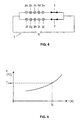
- FIG. 4 shows a further embodiment of the electrical device according to the invention Consumer chain 1 shown schematically.
- This consumer chain 1 are two groups of electrical consumers 2a - 2e, 2f - 2j respectively connected in series and these two groups connected in parallel.
- two current switches 3, 3 'are provided these are each connected in series with a group of lamps 2a-2e, 2f-2j are.
- This embodiment can be used in particular for fairy lights with many lamps be an advantage. Reached because of the failure in one of the two branched lines the current strength is a critical value, at to which the power switch responds, only the one with the deactivated one Lamps connected in series activated and only one of the two Branches shut off while the other branched Line can continue to operate normally. This will only turning off part of the lamps while the other Group continues to illuminate the object or decoration can serve.
- the characteristic curve of an electrical consumer chain according to the present invention is shown in FIG.
- the current I is plotted on the abscissa and the temperature T on the ordinate, which is to be expected at the individual electrical consumers at the corresponding current. If the current intensity I 0 is reached at which the temperature is Tmax, ie the maximum temperature which can be achieved by the electrical consumers and at which no overheating or damage occurs, the current switch 3 responds and the power supply to the chain is interrupted. This avoids a further increase in temperature at the electrical consumers, which can lead to overheating and possibly damage the consumer.
- the amperage at which the power switch is activated should be established in the manufacture of the electrical consumer chain.
- the switch can be designed so that different maximum permissible Current strengths can be set optionally.
Landscapes
- Circuit Arrangement For Electric Light Sources In General (AREA)
- Keying Circuit Devices (AREA)
Abstract
Description
- Figur 1
- ein schematisches Schaltdiagramm einer Ausführungsform der erfindungsgemäßen elektrischen Verbraucherkette in einem ersten Zustand;
- Figur 2
- ein schematisches Schaltdiagramm der Ausführungsform der erfindungsgemäßen elektrischen Verbraucherkette von Figur 1 in einem zweiten Zustand;
- Figur 3
- ein schematisches Schaltdiagramm der Ausführungsform der erfindungsgemäßen elektrischen Verbraucherkette von Figur 1 in einem dritten Zustand;
- Figur 4
- ein schematisches Schaltdiagramm einer weiteren Ausführungsform der erfindungsgemäßen elektrischen Verbraucherkette; und
- Figur 5
- eine Kennlinie einer erfindungsgemäßen elektrischen Verbraucherkette nach Figur 1.
Claims (8)
- Elektrische Verbraucherkette für Netzanschluss, bei der mindestens zwei elektrische Verbraucher (2a - 2j) in Reihe geschaltet sind und an mindestens einem elektrischen Verbraucher (2a - 2j) eine Strombrücke vorgesehen ist, dadurch gekennzeichnet, dass die elektrische Verbraucherkette (1) mindestens einen Stromschalter (3) aufweist, der bei Erreichen einer vorbestimmten Stromstärke die Spannungszufuhr zu den in Reihe geschalteten elektrischen Verbrauchern (2a - 2j) abschaltet.
- Elektrische Verbraucherkette gemäß Anspruch 1, dadurch gekennzeichnet, dass die elektrischen Verbraucher (2a - 2j) Glühlampen darstellen.
- Elektrische Verbraucherkette gemäß einem der Ansprüche 1 oder 2, dadurch gekennzeichnet, dass der Stromschalter (3) in Reihe geschaltet ist zu den in Reihe geschalteten elektrischen Verbrauchern (2a - 2j).
- Elektrische Verbraucherkette gemäß einem der vorstehenden Ansprüche, dadurch gekennzeichnet, dass der Stromschalter (3) in einem bereits in der elektrischen Verbraucherkette (1) vorhandenen Gehäuse vorgesehen ist.
- Elektrische Verbraucherkette gemäß einem der vorstehenden Ansprüche, dadurch gekennzeichnet, dass die Stromschalterrücksetzung selbsttätig erfolgt.
- Elektrische Verbraucherkette gemäß einem der Ansprüche 1, 2, 3 oder 4 dadurch gekennzeichnet, dass die Stromschalterrücksetzung durch einen separaten Schalter erfolgt.
- Elektrische Verbraucherkette gemäß einem der Ansprüche 1, 2, 3 oder 4 dadurch gekennzeichnet, dass die Stromschalterrücksetzung durch Trennen der Kette vom Netz erfolgt.
- Elektrische Verbraucherkette gemäß einem der vorstehenden Ansprüche, dadurch gekennzeichnet, dass die Stromstärke, bei der der Stromschalter (3) aktiviert wird, in bezug auf die maximale Leistung der elektrischen Verbraucher (2a - 2j) bestimmt wird.
Applications Claiming Priority (2)
| Application Number | Priority Date | Filing Date | Title |
|---|---|---|---|
| DE10048978A DE10048978A1 (de) | 2000-09-27 | 2000-09-27 | Elektrische Verbraucherkette für Netzanschluss |
| DE10048978 | 2000-09-27 |
Publications (2)
| Publication Number | Publication Date |
|---|---|
| EP1196011A2 true EP1196011A2 (de) | 2002-04-10 |
| EP1196011A3 EP1196011A3 (de) | 2004-03-03 |
Family
ID=7658554
Family Applications (1)
| Application Number | Title | Priority Date | Filing Date |
|---|---|---|---|
| EP01119854A Withdrawn EP1196011A3 (de) | 2000-09-27 | 2001-08-16 | Elektrische Verbraucherkette für Netzanschluss |
Country Status (3)
| Country | Link |
|---|---|
| EP (1) | EP1196011A3 (de) |
| DE (1) | DE10048978A1 (de) |
| NO (1) | NO20014003L (de) |
Cited By (1)
| Publication number | Priority date | Publication date | Assignee | Title |
|---|---|---|---|---|
| EP4080410A1 (de) * | 2021-04-23 | 2022-10-26 | Willi Römpp | Identifizierungseinheit zur anbringung an einem logistikobjekt, brief oder paket |
Family Cites Families (2)
| Publication number | Priority date | Publication date | Assignee | Title |
|---|---|---|---|---|
| US4223248A (en) * | 1978-09-06 | 1980-09-16 | Tong George K K | Fused light string set |
| US4425605A (en) * | 1979-01-29 | 1984-01-10 | Sam Cheng | Decorative lighting string for assembly with overcurrent protection |
-
2000
- 2000-09-27 DE DE10048978A patent/DE10048978A1/de not_active Withdrawn
-
2001
- 2001-08-16 NO NO20014003A patent/NO20014003L/no not_active Application Discontinuation
- 2001-08-16 EP EP01119854A patent/EP1196011A3/de not_active Withdrawn
Cited By (1)
| Publication number | Priority date | Publication date | Assignee | Title |
|---|---|---|---|---|
| EP4080410A1 (de) * | 2021-04-23 | 2022-10-26 | Willi Römpp | Identifizierungseinheit zur anbringung an einem logistikobjekt, brief oder paket |
Also Published As
| Publication number | Publication date |
|---|---|
| DE10048978A1 (de) | 2002-04-11 |
| NO20014003D0 (no) | 2001-08-16 |
| EP1196011A3 (de) | 2004-03-03 |
| NO20014003L (no) | 2002-04-02 |
Similar Documents
| Publication | Publication Date | Title |
|---|---|---|
| EP2609365B1 (de) | Leuchtmittel, insbesondere zum betrieb in fassungen für leuchtstofflampen | |
| EP3338149B1 (de) | Verfahren zum betreiben eines stromverteilers sowie stromverteiler | |
| EP1044851B1 (de) | Vorrichtung für einen Powerring | |
| DE60010225T2 (de) | Bausatz zum umsetzen von leuchtstoffleuchte von induktiven in elektronischen betrieb | |
| EP2567149A2 (de) | Leuchtmittel zum ersatz einer leuchtstoffröhre | |
| DE2102077C3 (de) | Bremsbelagabnutzungs-Anzeigevorrichtung | |
| DE112013002885T5 (de) | Spannungsumwandlungsapparat, Stromerzeugungssystem und Spannungsumwandlungsverfahren | |
| DE19713935A1 (de) | Stromversorgungsschaltung für eine Entladungslampe | |
| DE10301954A1 (de) | In einem Fahrzeug eingebaute elektrische Leistungsversorgungsvorrichtung | |
| EP2707888B1 (de) | Schaltvorrichtung | |
| EP2500208A2 (de) | Schutzschaltungsanordnung | |
| DE102018129211A1 (de) | Bus-System zur elektrischen Versorgung einer Mehrzahl von Lasten und hiermit ausgestattetes Fluggerät | |
| DE19781744B4 (de) | In Reihe geschaltete Lichterkette mit Glühfadennebenwiderstand | |
| DE102016100053A1 (de) | Solarzellenmodul und ein Verfahren zur Herstellung eines Solarzellenmoduls | |
| DE102023203236B3 (de) | Ansteuerschaltung für einen Hybridschalter und Hybridschalter | |
| DE10048978A1 (de) | Elektrische Verbraucherkette für Netzanschluss | |
| DE202013000880U1 (de) | Schaltungsanordnung zum Betreiben mindestens einer LED und System aus einem Vorschaltgerät und einer Retrofit-Lampe | |
| EP1592106A1 (de) | Vorrichtung zum Anschliessen einer elektrischen Last an eine Energiequelle | |
| DE102014204875B4 (de) | Verfahren zum Umbau einer Leuchte für den Betrieb einer Leuchtstoffröhre zu einer Leuchte für den Betrieb einer LED-Röhre | |
| DE102016121930A1 (de) | Leuchtsystem | |
| DE202008009007U1 (de) | Konstantstrom-Verteiler | |
| DE112017001436T5 (de) | Lichtbogenunterdrückungsverbinder | |
| DE102011007042A1 (de) | Schutzschaltungsanordnung | |
| DE10126031C1 (de) | Wärmevorrichtung mit einem schmiegsamen Heizkörper | |
| DE202021105919U1 (de) | Gerade LED-Rohrleuchte |
Legal Events
| Date | Code | Title | Description |
|---|---|---|---|
| PUAI | Public reference made under article 153(3) epc to a published international application that has entered the european phase |
Free format text: ORIGINAL CODE: 0009012 |
|
| AK | Designated contracting states |
Kind code of ref document: A2 Designated state(s): AT BE CH CY DE DK ES FI FR GB GR IE IT LI LU MC NL PT SE TR |
|
| AX | Request for extension of the european patent |
Free format text: AL;LT;LV;MK;RO;SI |
|
| PUAL | Search report despatched |
Free format text: ORIGINAL CODE: 0009013 |
|
| AK | Designated contracting states |
Kind code of ref document: A3 Designated state(s): AT BE CH CY DE DK ES FI FR GB GR IE IT LI LU MC NL PT SE TR |
|
| AX | Request for extension of the european patent |
Extension state: AL LT LV MK RO SI |
|
| AKX | Designation fees paid | ||
| REG | Reference to a national code |
Ref country code: DE Ref legal event code: 8566 |
|
| STAA | Information on the status of an ep patent application or granted ep patent |
Free format text: STATUS: THE APPLICATION IS DEEMED TO BE WITHDRAWN |
|
| 18D | Application deemed to be withdrawn |
Effective date: 20040904 |