EP1195943A2 - System and method for integrating capability information from multiple components - Google Patents
System and method for integrating capability information from multiple components Download PDFInfo
- Publication number
- EP1195943A2 EP1195943A2 EP01308505A EP01308505A EP1195943A2 EP 1195943 A2 EP1195943 A2 EP 1195943A2 EP 01308505 A EP01308505 A EP 01308505A EP 01308505 A EP01308505 A EP 01308505A EP 1195943 A2 EP1195943 A2 EP 1195943A2
- Authority
- EP
- European Patent Office
- Prior art keywords
- tag
- component
- tags
- predefined
- defining
- Prior art date
- Legal status (The legal status is an assumption and is not a legal conclusion. Google has not performed a legal analysis and makes no representation as to the accuracy of the status listed.)
- Withdrawn
Links
- 238000000034 method Methods 0.000 title abstract description 11
- 230000002093 peripheral effect Effects 0.000 claims description 13
- 101100110009 Caenorhabditis elegans asd-2 gene Proteins 0.000 description 5
- 238000010586 diagram Methods 0.000 description 4
- 101100079986 Caenorhabditis elegans nrfl-1 gene Proteins 0.000 description 3
- 101100084165 Caenorhabditis elegans prdx-2 gene Proteins 0.000 description 2
- 238000012986 modification Methods 0.000 description 2
- 230000004048 modification Effects 0.000 description 2
- 238000006467 substitution reaction Methods 0.000 description 2
- 101100480513 Caenorhabditis elegans tag-52 gene Proteins 0.000 description 1
- 230000010354 integration Effects 0.000 description 1
- 238000012423 maintenance Methods 0.000 description 1
Images


Classifications
-
- H—ELECTRICITY
- H04—ELECTRIC COMMUNICATION TECHNIQUE
- H04L—TRANSMISSION OF DIGITAL INFORMATION, e.g. TELEGRAPHIC COMMUNICATION
- H04L41/00—Arrangements for maintenance, administration or management of data switching networks, e.g. of packet switching networks
- H04L41/12—Discovery or management of network topologies
Definitions
- the present invention generally relates to an improved system and method for integrating capability information from a plurality of components into a single view file. More specifically, it relates to a system and method for integrating capability information from a plurality of components into a single system view file using Standard Generalized Markup Language.
- a prior system of gathering capability information required a query of a specific URI for a requested component.
- each component designates a separate URI for its content page. For example, if a device management system inquires whether a device supports a particular capability (e.g., a status page), the device management system must query the specific URI for the page relating to that particular capability.
- the prior system requires hard-coded relationships between the components prior to usage, because the system must know all the URIs in advance.
- One problem is that the prior system does not provide for discovery of new capabilities that have not previously been hard-coded. Furthermore, because the structure of the prior system has a different URI, it is difficult to change the content page of the system.
- a device management system may query a device to determine whether it supports specific feature. Although a particular device in the system does support that specific feature, there is no guarantee that the World Wide Web content in that device supports that same feature.
- a primary object of the present invention is to provide an improved system for integrating capability information into a single system view in Standard Generalized Markup Language.
- Another object of the present invention is to provide an improved system for integrating capability information that can determine the capabilities of multiple components more easily.
- Yet another object of the present invention is to provide an improved system for integrating capability information that can determine the capability of multiple components more accurately.
- a further object of the present invention is to provide an improved system for integrating capability information that aggregates multiple components connected to other multiple components into a single network view.
- Still a further object of the present invention is to provide an improved system for integrating capability information of multiple components that is more accessible over the Internet.
- the present invention generally relates to an improved system and method for integrating capability information from a plurality of components into a single system view file. More particularly, it relates to a system and method for integrating capability information from a plurality of components into a single system view file using Standard Generalized Markup Language.
- the present invention provides an improved system and method for integrating capability information from a plurality of components in a predefined system into a single system view file.
- the present invention includes a component tag for each of the components for defining information relating to the component and at least one predefined tag for each component tag for defining information relating to the capability of the component.
- the tags are listed in a single system view file using Standard Generalized Markup Language.
- the present invention is directed to an improved system and method for integrating capability information from a plurality of components into a single system view file.
- tags for system definitions, each component within a predefined system is uniquely identified, and its capability is defined in a single system view file.
- the relationships of all the different components are integrated into a single network view, which results in a simpler and more accurate representation of the capability content.
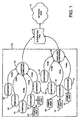
- FIG. 1 a schematic exemplary diagram of a network architecture is shown with the implementation of computers and their components as a predefined system.
- the present invention is preferably implemented with Extensible Markup Language ("XML").
- XML Extensible Markup Language
- Specific XML based tags are used to describe the components within the system, which will be herein referred to as Peripheral Capability Markup Language (“PCML”).
- PCML Peripheral Capability Markup Language
- FIG. 1 two computer components 10 are included, as an example, in a predefined system 12, giving a single network view 14.
- Each computer component 10 is shown to be associated with multiple components 10' as an example. Furthermore, a component 10' maybe linked to other components 10', or the components 10' may be not linked at all.
- a system view file 16 using Standard Generalized Markup Language keeps all the tags that define specific information of the component. Thus, the structural information relating to the predefined system 14 can be obtained through one location, specifically the system view file 16.
- the component 10' can be anything that relates to the predefined system, such as a personal computer, a server computer, a client computer, a peripheral device, a protocol, a software program and a firmware program.
- the network architecture of the present invention can be implemented in numerous ways. If, for example, the component computer 10 is a server computer, the server computer, in turn, could be linked to other computer components 10 that can be connected to other components 10', such as a peripheral device. All these various implementations are contemplated and are within the scope of the present invention.
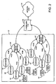
- FIG. 2 A schematic exemplary diagram of another network architecture implementing multiple peripheral devices is shown in FIG. 2. Similar to the previous implementation of a predefined computer system 12, the predefined peripheral device system 12' has two peripheral device components 10", as an example. And each device is associated with different components 10'.
- the tags can be defined in a variety of ways to better fit the predefined system. For example, a predefined system can have a computer component 10 and a peripheral device component 10" that are not connected to each other.
- the present invention is very flexible in that it allows for almost any predefined system by customizing the tags and their structures.
- the components 10' of the peripheral device components 10" have components associated with them while other components 10' do not. All the information relating to the peripheral device system 12' is kept in the system view file 16.
- the system view file aggregates the predefined system 12' into a single network view 14.
- the components 10' can be, for example, a software program or a firmware program for the peripheral device component 10"
- the components 10' can also be software program or firmware program relating to the component depending on what the component is.
- an endless variation of network architecture can be created, and these variations are within the scope of the present invention.
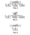
- the system view file tag 18 preferably consists of a system view file name tag 20, and a system view file location tag 22, a system view file version tag 24.
- the system view file name tag 20 identifies the system view file 16 in the predefined system
- the system view file location tag 22 identifies where the system view file 16 is located.
- the system view file version tag 24 indicates the version number of the PCML being used for the system view file 16. Because the present invention is very flexible in its structure and design, other tags can be added or altered according to need and design. However, these preferred tags are useful for references to network administrators and for maintenance of the system view file 16.
- all the tags will have a starting tag (e.g., ⁇ PCML> shown in FIG. 10) and an ending tag (e.g., ⁇ /PCML> shown in FIG. 10) according to the XML structure as defined by the World Wide Web Consortium ("W3C").
- W3C World Wide Web Consortium
- the system view file tag 18 begins with a starting tag bearing the system view file name, followed by an ending tag.
- the starting tag in this example, will be " ⁇ PCML>” and the ending tag 40 will be " ⁇ /PCML>” (shown in FIG. 10).
- All the information relating to the PCML i.e., PCML encoded data
- the starting tag i.e., ⁇ PCML>
- the ending tag i.e., ⁇ /PCML>
- the starting tag of the system view file tag defines the beginning of the system view file, and vice versa
- the ending tag 40 defines the end of the file.
- all the tags in the system view file 16 will have a starting tag and an ending tag if implemented with XML.
- An access right tag 26 can be included for any of the tags in the system for defining the highest access right of that selected tag, which is preferably defined as either none 28, readOnly 30 or readWrite 32.
- the system view file tag 18 can have an access right tag 26 defining the highest access right allowed for the whole system.
- the system view file tag 18 need not have to have an access right tag at all. In that event, the predefined system does not have any limitation for accessing the predefined system. However, if an access right tag 26 is included for any of the tags in the system, the limitation applies only to that particular tag.
- both the system view file tag and the predefined tag include an access right tag 26, it is preferred that the access right of the predefined tag does not exceed the access right of the system view file tag. If an access right tag is not defined for a predefined tag, that component will take the default access right of the system, which will be the same access right of the system view file tag.
- FIGS. 5, 6, 7 and 8 the preferred architecture of the component tag is shown in FIG. 5 and other predefined tags defining information relating to the capability of the component is shown in FIGS. 6, 7 and 8. Since a plurality of components 10' will be included in a single predefined system, each component should have its own component tag 34 in the system view file 16. Furthermore, a component tag 34 preferably includes a component name tag 36 to uniquely identify each component 10' in the system. Depending on the type of components 10' defined, the capability between them will vary greatly. As a result, many different tags relating to the capability of the component can be defined, and these other tags are within the scope of the present invention. In FIGS. 6, 7 and 8, the most commonly used capability are defined and shown as an example.
- a component tag 34 can include a protocol tag 38 for defining information relating to an available protocol of the component indicated by the component tag. Again, it is preferred that a protocol tag 38 be defined for each available protocol.
- the structure of the protocol preferably includes a protocol name tag 40 for uniquely identifying each protocol and a uniform request indicator tag 42 for indicating the Internet address of the protocol.
- Component capability can also relate to security and licensing information.
- a component identification tag 44 can be used to relate that type of information of the component 10', which is shown in FIG. 7.
- the component identification tag 44 preferably includes a component version tag 46 and a component signature tag 48.
- the component version tag 46 defines the version of number of the component 10', and the component signature tag defines the certification number of the digital signature of the component, assuming that the component has such a signature.
- the component version tag 46 is preferably divided into a revision tag 50, a major tag 52 and a minor tag 54, for indicating the number of revisions for the component, the number of major revisions, and the number of minor revisions, respectively.
- Another component capability relates to user interface information, which defines the user information of the component 10'. If the component includes user interface information, a user interface tag 56 will be included to define it.
- the preferred architecture of the user interface tag is shown in FIG. 8.
- the user interface tag is preferably divided into two main tags, more specifically a management view tag 58 and a user view tag 60.
- the management view tag 58 defines the allowance level for a network administrator of the component; and the user view tag 60 defines the allowance level for the general user of the component.
- Both can further include an element tag 62 for defining information relating to an element of the view tags 58, 60 and a language tag 64 to designate one or more languages that can be displayed to the user.
- each element tag 62 can further be divided into an element name tag 66 and an element URI tag 68.
- the element name tag 66 uniquely identifies each of the elements, since there may be multiple elements for the view tags 58, 60.
- the element URI tag 68 defines the URI for that element tag 62.
- tags and their architectures have been shown in the above figures. However, it should be understood that not all of the tags referenced above must be included in the programming text of the file. Rather, this is just a reference of all of the tags that a programmer can use to define the components and capabilities that are recognized within the system. However, as previously mentioned, all of the tags included are only meant as examples. The present invention contemplated using other predefined tags and additional tags that are necessary to accommodate a specific predefined system, and these other tags are within the scope of the present invention.
- the present invention contemplate implementing a program that will automatically maintain the system view file. For example, tags relating to the new component are created and added to the system view file when the component is first introduced into the predefined system. Alternatively, tags are deleted from the system view file when a component is excluded from the predefined system. As a result, the system view file is automatically updated with little human intervention.
- DTD document type definition
- the DTD can be changed depending on the predefined system. For example, a more complex system would most likely require more tags, which can be different from the predefined tags listed in the DTD. These other additional tags are contemplated and are within the scope of the present invention.
- the first part of the system view file 16 include the DTD of the PCML encoded data and some programmer references as human readable text comments.
- the document type of the file is also referenced in the first few lines.
- the system view file 16 is a PCML version 1.0 file.
- a list of all the tags that are readable by the machine are referenced in the remaining text comments.
- a component 10' in the predefined system can be almost anything depending on the system type.
- a component 10' can be a personal computer, a server computer, a client computer, a peripheral device, a protocol, a software program or a firmware program.
- the component tag 34 preferably includes a component name tag 36 to uniquely identify each of the components 10' in the predefined system, since there may be multiple components included in the system view file 16.
- Two components 10' are included in the example: a component named "formatter” and "JetDirect Print Server.” However, in practice, there will be many components 10' listed in the system view file 16, and each component is also defined by a component starting tag and a component ending tag according to the structure of the XML, which is ⁇ component> and ⁇ /component>.
- an access right tag 26 should be defined, specifically within the component name tag 36.
- the access right tag 26 can be defined as none, read Only or readWrite. As shown in FIG. 11, the component description is located between the component starting tag and component ending tag, and each component tag is located between the system view file starting tag and the system view file ending tag.
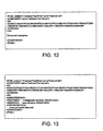
- FIGS. 12 and 13 The preferred XML programming structure of the component identification tag 44 and the component user interface tag 56 are shown in FIGS. 12 and 13, respectively.
- the component signature tag 48 ( ⁇ ID>) and component version tag 46 ( ⁇ VERSION>) are located in between the starting and ending tags of the component identification tag 44, which means that these tags located in between relate only to that component identification tag of that particular component 10'.
- the management view tag 58 ( ⁇ MGMTVIEW>) and the user view tag 60 ( ⁇ USERVIEW>) are located between the starting and ending tags of the component user interface tag 58 ( ⁇ USERINTERFACE>).
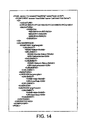
- FIG. 14 the preferred XML programming structure of the element tag 62 and the language tag 64 of the view tags 58, 60 are shown.
- the element name tag 66 ⁇ NAME>
- the element URI tag 68 ⁇ URI>
- FIG. 14 shows an example of the programming structure of a sample system view file with the tags referenced in FIGS. 3 to 8. However, it is meant only as an example, because a typical system view file 16 can be more complex and can contain many more components 10' within the predefined system. Again, because of the flexibility of the present invention, other programming structures are contemplated and are within the present invention.
Landscapes
- Engineering & Computer Science (AREA)
- Computer Networks & Wireless Communication (AREA)
- Signal Processing (AREA)
- Information Retrieval, Db Structures And Fs Structures Therefor (AREA)
- Devices For Executing Special Programs (AREA)
- Debugging And Monitoring (AREA)
Abstract
Description
Claims (10)
- A system for integrating capability information from a plurality of components (10, 10', 10") in a predefined system (12, 12') into a single system view file (16), comprising:wherein said tags are listed in a single system view file (16) using Standard Generalized Markup Language.a component tag (34) for each said plurality of components for defining information relating to said component; and,at least one predefined tag (44, 56) for each said component tag for defining information relating to the capability of said component;
- The system as defined in claim 1 wherein said component is one from the group consisting of a personal computer, a server computer, a client computer, a peripheral device, a protocol, a software program and a firmware program.
- The system as defined in claim 1 wherein at least one of said component tags (34) and said predefined tags further comprising:a starting tag to define the beginning of said tag; and,an ending tag to define the end of said tag.
- The system as defined in claim 1 wherein at least one of said component tags (34) and predefined tags further comprising an access right tag (26) for defining the highest access rights of said selected tag.
- The system as defined in claim 1 further comprising a system view file tag (18) for defining information relating to said system view file.
- The system as defined in claim 1 wherein said component tag (34) further comprising a component name tag (36) for uniquely identifying each said component.
- The system as defined in claim 1 wherein said at least one predefined tag (44, 56) is a component identification tag (44) for defining security and licensing information relating to said component.
- The system as defined in claim 9 wherein said component identification tag (44) further comprising:a component version tag (46) for defining the version number of said component; and,a component signature tag (48) for defining the certificate number for the digital signature of said component.
- The system as defined in claim 1 wherein said at least one tag is a protocol tag (38) for defining information relating to an available protocol of said component.
- The system as defined in claim 1 wherein said at least one tag is a component user interface tag (56) for defining user information relating to said component.
Applications Claiming Priority (2)
| Application Number | Priority Date | Filing Date | Title |
|---|---|---|---|
| US68007000A | 2000-10-05 | 2000-10-05 | |
| US680070 | 2000-10-05 |
Publications (2)
| Publication Number | Publication Date |
|---|---|
| EP1195943A2 true EP1195943A2 (en) | 2002-04-10 |
| EP1195943A3 EP1195943A3 (en) | 2003-12-17 |
Family
ID=24729524
Family Applications (1)
| Application Number | Title | Priority Date | Filing Date |
|---|---|---|---|
| EP01308505A Withdrawn EP1195943A3 (en) | 2000-10-05 | 2001-10-04 | System and method for integrating capability information from multiple components |
Country Status (1)
| Country | Link |
|---|---|
| EP (1) | EP1195943A3 (en) |
Family Cites Families (1)
| Publication number | Priority date | Publication date | Assignee | Title |
|---|---|---|---|---|
| US5995977A (en) * | 1997-08-15 | 1999-11-30 | International Business Machines Corporation | Module configuration systems, methods and computer program products for data processing systems |
-
2001
- 2001-10-04 EP EP01308505A patent/EP1195943A3/en not_active Withdrawn
Also Published As
| Publication number | Publication date |
|---|---|
| EP1195943A3 (en) | 2003-12-17 |
Similar Documents
| Publication | Publication Date | Title |
|---|---|---|
| Liang et al. | Ogc sensorthings api part 1: Sensing version 1.1 | |
| JP4726545B2 (en) | Method, system and apparatus for discovering and connecting data sources | |
| US6629127B1 (en) | Methods and systems for processing HTTP requests | |
| US7437375B2 (en) | System and method for communicating file system events using a publish-subscribe model | |
| US7770180B2 (en) | Exposing embedded data in a computer-generated document | |
| US7574431B2 (en) | Remote data collection and control using a custom SNMP MIB | |
| US20060004759A1 (en) | System and method for file system content processing | |
| US7752632B2 (en) | Method and system for exposing nested data in a computer-generated document in a transparent manner | |
| US9582596B2 (en) | Preventing not found error (404) responses on dynamically loaded missing images | |
| Mueller et al. | OGC wps 2.0 interface standard. Version 2.0. | |
| US7660803B2 (en) | Policy-based management method and system for printing of extensible markup language (XML) documents | |
| US20050289159A1 (en) | Web-enabled real-time link selection apparatus and method | |
| US6275860B1 (en) | Method and apparatus for synchronizing function values in a multiple protocol system | |
| Liang et al. | OGC SensorThings API Part 2–Tasking Core, Version 1.0. | |
| US20080104226A1 (en) | Using feed usage data in an access controlled team project site environment | |
| EP1195943A2 (en) | System and method for integrating capability information from multiple components | |
| Buraga | A model for accessing resources of the distributed file systems | |
| JP4429229B2 (en) | Directory information providing method, directory information providing apparatus, directory information providing system, and program | |
| JP4199916B2 (en) | Document management method and apparatus | |
| US20080270409A1 (en) | Data, Structure, Structured Data Management System, Structured Data Management Method and Structured Data Management Program | |
| US20040210913A1 (en) | Method of accessing resource description framework based information | |
| JP2017182122A (en) | Data provision system, access right management device, data provision method, and computer program | |
| JP2005275759A (en) | Electronic document management system, user attribute management device, electronic document management device, electronic document management method, and electronic document management program | |
| EP1654641A2 (en) | Method and system for probability-based validation of extensible markup language documents | |
| JP2011039834A (en) | Log conversion system |
Legal Events
| Date | Code | Title | Description |
|---|---|---|---|
| PUAI | Public reference made under article 153(3) epc to a published international application that has entered the european phase |
Free format text: ORIGINAL CODE: 0009012 |
|
| AK | Designated contracting states |
Kind code of ref document: A2 Designated state(s): AT BE CH CY DE DK ES FI FR GB GR IE IT LI LU MC NL PT SE TR |
|
| AX | Request for extension of the european patent |
Free format text: AL;LT;LV;MK;RO;SI |
|
| PUAL | Search report despatched |
Free format text: ORIGINAL CODE: 0009013 |
|
| AK | Designated contracting states |
Kind code of ref document: A3 Designated state(s): AT BE CH CY DE DK ES FI FR GB GR IE IT LI LU MC NL PT SE TR |
|
| AX | Request for extension of the european patent |
Extension state: AL LT LV MK RO SI |
|
| RIC1 | Information provided on ipc code assigned before grant |
Ipc: 7G 06F 9/46 B Ipc: 7G 06F 17/50 B Ipc: 7G 06F 17/30 B Ipc: 7G 06F 9/44 B Ipc: 7G 06F 9/445 B Ipc: 7H 04L 12/24 A |
|
| 17P | Request for examination filed |
Effective date: 20040527 |
|
| AKX | Designation fees paid |
Designated state(s): DE FR GB |
|
| STAA | Information on the status of an ep patent application or granted ep patent |
Free format text: STATUS: THE APPLICATION HAS BEEN WITHDRAWN |
|
| 18W | Application withdrawn |
Effective date: 20041104 |