EP1195923A2 - Radio communication system having radio link control layer and data processing method in the same - Google Patents
Radio communication system having radio link control layer and data processing method in the same Download PDFInfo
- Publication number
- EP1195923A2 EP1195923A2 EP20010121920 EP01121920A EP1195923A2 EP 1195923 A2 EP1195923 A2 EP 1195923A2 EP 20010121920 EP20010121920 EP 20010121920 EP 01121920 A EP01121920 A EP 01121920A EP 1195923 A2 EP1195923 A2 EP 1195923A2
- Authority
- EP
- European Patent Office
- Prior art keywords
- pdus
- module
- data
- communication system
- radio communication
- Prior art date
- Legal status (The legal status is an assumption and is not a legal conclusion. Google has not performed a legal analysis and makes no representation as to the accuracy of the status listed.)
- Granted
Links
Images






Classifications
-
- H—ELECTRICITY
- H04—ELECTRIC COMMUNICATION TECHNIQUE
- H04L—TRANSMISSION OF DIGITAL INFORMATION, e.g. TELEGRAPHIC COMMUNICATION
- H04L1/00—Arrangements for detecting or preventing errors in the information received
- H04L1/12—Arrangements for detecting or preventing errors in the information received by using return channel
- H04L1/16—Arrangements for detecting or preventing errors in the information received by using return channel in which the return channel carries supervisory signals, e.g. repetition request signals
- H04L1/18—Automatic repetition systems, e.g. Van Duuren systems
- H04L1/1829—Arrangements specially adapted for the receiver end
- H04L1/1835—Buffer management
-
- H—ELECTRICITY
- H04—ELECTRIC COMMUNICATION TECHNIQUE
- H04B—TRANSMISSION
- H04B7/00—Radio transmission systems, i.e. using radiation field
- H04B7/24—Radio transmission systems, i.e. using radiation field for communication between two or more posts
- H04B7/26—Radio transmission systems, i.e. using radiation field for communication between two or more posts at least one of which is mobile
- H04B7/2603—Arrangements for wireless physical layer control
-
- H—ELECTRICITY
- H04—ELECTRIC COMMUNICATION TECHNIQUE
- H04L—TRANSMISSION OF DIGITAL INFORMATION, e.g. TELEGRAPHIC COMMUNICATION
- H04L1/00—Arrangements for detecting or preventing errors in the information received
- H04L1/12—Arrangements for detecting or preventing errors in the information received by using return channel
- H04L1/16—Arrangements for detecting or preventing errors in the information received by using return channel in which the return channel carries supervisory signals, e.g. repetition request signals
- H04L1/18—Automatic repetition systems, e.g. Van Duuren systems
- H04L1/1867—Arrangements specially adapted for the transmitter end
- H04L1/1874—Buffer management
-
- H—ELECTRICITY
- H04—ELECTRIC COMMUNICATION TECHNIQUE
- H04L—TRANSMISSION OF DIGITAL INFORMATION, e.g. TELEGRAPHIC COMMUNICATION
- H04L63/00—Network architectures or network communication protocols for network security
- H04L63/04—Network architectures or network communication protocols for network security for providing a confidential data exchange among entities communicating through data packet networks
- H04L63/0428—Network architectures or network communication protocols for network security for providing a confidential data exchange among entities communicating through data packet networks wherein the data content is protected, e.g. by encrypting or encapsulating the payload
-
- H—ELECTRICITY
- H04—ELECTRIC COMMUNICATION TECHNIQUE
- H04W—WIRELESS COMMUNICATION NETWORKS
- H04W12/00—Security arrangements; Authentication; Protecting privacy or anonymity
- H04W12/03—Protecting confidentiality, e.g. by encryption
- H04W12/037—Protecting confidentiality, e.g. by encryption of the control plane, e.g. signalling traffic
-
- H—ELECTRICITY
- H04—ELECTRIC COMMUNICATION TECHNIQUE
- H04W—WIRELESS COMMUNICATION NETWORKS
- H04W28/00—Network traffic management; Network resource management
- H04W28/02—Traffic management, e.g. flow control or congestion control
- H04W28/06—Optimizing the usage of the radio link, e.g. header compression, information sizing, discarding information
-
- H—ELECTRICITY
- H04—ELECTRIC COMMUNICATION TECHNIQUE
- H04W—WIRELESS COMMUNICATION NETWORKS
- H04W92/00—Interfaces specially adapted for wireless communication networks
- H04W92/04—Interfaces between hierarchically different network devices
- H04W92/10—Interfaces between hierarchically different network devices between terminal device and access point, i.e. wireless air interface
Definitions
- the present invention relates to a radio communication system having a radio link control (RLC) layer and a data processing method in the same.
- RLC radio link control
- IMT-2000 will be one of them.
- An RLC layer is the second layer of 3GPP as a protocol layer controlling data links corresponding to the second layer of OSI 7-layered model.
- RLC species used in 3GPP are mainly divided into Tr(transparent) mode to which no RLC header is added and NTR(non-transparent mode) to which RLC header is added.
- NTr mode is subdivided into UM mode(unacknowledged mode) having no ACK(acknowledgement) signal from a receive stage and AM mode(acknowledged mode) having an ACK signal from the receive stage.
- RLC presently uses three modes of Tr, UM, and AM, in which AM entity structure is shown FIG. 1.
- FIG. 1 illustrates a block diagram of RLC AM entity structure according to a related art.
- segmentation and concatenation are carried out through a block 101 so as to change SDUs(service data units) stepping down from an upper layer into uniform-sized protocol data units (PDUs) and headers containing sequence numbers SN are added to PDUs through a block 102.
- PDUs protocol data units
- PDU to which the header is added is transmitted downward as well as stored in a retransmission buffer 103 for a later use such as retransmission which may occur in future.
- the PDU flown down through a multiplexer 104 under goes a ciphering through a block 105 for data security and then is temporarily stored in a transmission buffer 106 so as to be transmitted to a set fields block 107.
- set field block 107 other fields such as DC and poll field and the like except the sequence number SN of the RLC header are set and then transmitted to another AM entity corresponding to a receiving side.
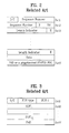
- FIG. 2 illustrates a structure of AMD PDU.
- format of the AMD PDU is constructed with a header and LI(length indicator) group, data, and PAD(padding) or piggybacked status PDU.
- the header includes a sequence number as a field representing the order numbers of the respective AMP PDUs, an 1-bit D/C field informing whether the corresponding AMD PDU carries data information or control information, an 1-bit polling field(P field) asking a receiving side of a status report, a 2-bit HE(header extension) field informing whether next data are data or LI and E bit, and an 1-bit E(extension) field informing whether a next field is data or LI and E bit.
- the LI part in the AMD PDU is constructed with LI and E bit, in which LI is a filed indicating boundaries of the respective SDUs when the PDU includes a plurality of SDUs.
- Each LI represents an octet count from the first octet of the data part to the last octet of the respective SDUs, and the respective LIs for the SDUs included in the PDU are called the LI group.
- the data part including at least one SDU is a field corresponding to the SDUs stepping down from the upper layer.
- padding is carried out so as to octet-align the sizes of the entire PDUs.
- the foregoing ciphering is carried out on the AMD PDU.
- the first two octets which are the header part, including the sequence number are not ciphered.
- the rest thereof is ciphered.
- control PDU exists as well as the AMD PDU.
- the control PDU includes a status PDU carrying status information, reset PDU resetting AM entity, and reset ACK PDU informing the acknowledgement(ACK) of the reset PDU.
- FIG. 3 illustrates a structure of status PDU
- FIG. 4 illustrates a structure of reset ACK PDU for explaining the reset and the reset ACK PDU.
- control PDUs which are generated from the RLC control unit, are transmitted to the set fields block without undergoing the ciphering, set D/C and PDU type fields, and then transmitted to RLC AM entity corresponding to the receiving side.
- a D/C field is set as 1 for the AMD PDU but as 0 for the control PDU.
- padding(PAD) is carried out thereon.
- the set fields block 107 enables to transmit status PDU instead of PAD so as to increase the data transmission efficiency.
- the status PDU is called piggybacked status PDU.
- a demultiplex/routing part 108 checks the D/C field. If a D/C field value is 0, the control PDU is instantly sent upward to the RLC control unit 100 since '0' corresponds to the control PDU. If the D/C field value is 1, the AMD PDU is instantly sent upward to the receiver buffer 109 since '1' corresponds to the AMD PDU.
- the RLC AM entity enables to use one or two logical channels for one radio bearer set-up.
- solid and dotted lines indicate the cases of using one or two logical channels, respectively.
- the AMD PDU is immediately transmitted to the receiver buffer 109 and the control PDU is transmitted to the RLC control unit 100 via the demultiplex/routing part 108.
- the receiver buffer 109 which checks the receiving statuses of the respective AMD PDUs, asking the transmitting side of retransmission of the not-received PDU by sending an NACK signal to the transmitting side when there is not-received AMD PDU.
- the PDUs having been stored in the receiver buffer 109 are stored until all the PDUs constructing a complete SDU are thoroughly received. After receiving all the corresponding PDUs, the receiver buffer 109 sends upward the PDUs by SDU unit.
- the PDUs are deciphered by a deciphering part 110, and data are extracted only by removing RLC headers and piggybacked information from the respective PDUs in a block 111.
- SDU is constructed with the pure data through the block 111.
- the SDU is sent upward to an upper layer through a reassembly part 112.
- the set fields block checks whether there exists PAD which the piggybacked status PDU enters in the AMD PDU. When such a PAD the piggybacked status PDU enters exists in the AMD PDU, the PAD has to be replaced by the piggybacked status PDU.
- the ciphered AMD PDU has to be deciphered in the set fields block in order to know the exact location of the PAD and whether the PAD exists.
- the ciphered AMD PDU should be deciphered to transmit the AMD PDU, whereby deciphering/ciphering has to be carried out in the set fields block unnecessarily.
- RLC AM entity corresponding to the receiving side has to be sent upward from the receiver buffer to the upper layer when the PDUs are sent upward.
- the PDUs stored in the receiver buffer have to be deciphered in order to know whether each of the PDUs belongs to which SDU.
- the receiver buffer needs a function of deciphering the PDU unnecessarily as well.
- the repeated ciphering/deciphering reduces processing speed and efficiency of the AMD PDU data and further degrades the system performance.
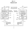
- FIG. 5 illustrates a construction of RLC UM entity according to a related art.
- segmentation and concatenation are carried out through a block 122 so as to change SDUs(service data units) stepping down from an upper layer through UM-SAP into uniform-sized protocol data units(PDUs).
- a ciphering part 123 ciphers the PDUs for data security.
- an RLC header part 124 adds headers containing sequence numbers SN to the PDUs so as to construct UMD(unacknowledged mode data) PDU.
- a transmission buffer 125 stores and transmits the UMD PDU to RLC UM entity corresponding to a receiving side.
- UMD PDU unacknowledged PDU
- AMD PDU acknowledgenowledged PDU
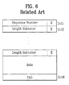
- format of the AMD PDU is constructed with a header and LI(length indicator) group, data, and PAD(padding).
- the header includes a sequence number as a field representing the order numbers of the respective PDUs and an 1-bit E(extension) field informing whether a next field is data, the LI or extension bit.
- the data part including at least one SDU is a field corresponding to the SDUs stepping down from the upper layer.
- padding is carried out so as to octet-align the sizes of the entire PDUs.
- the LI part in the UMD PDU is constructed with LI and E bit, in which LI is a filed indicating boundaries of the respective SDUs when the PDU includes a plurality of SDUs.
- Each LI represents an octet count from the first octet of the data part to the last octet of the respective SDUs, and the respective LIs for the SDUs included in the PDU are called the LI group.
- a structure of the UMD PDU is equal to that in FIG. 6, in which the first octet is the header including the sequence number and the header is not ciphered. Thus, the rest thereof is ciphered.
- RLC UM entity stores the transmitted UMD PDU in the receiver buffer 130. When all the PDUs constructing a complete SDU are thoroughly received, the stored PDUs are transmitted to a block 129 by SDU unit.
- the headers of the PDUs are removed in the block 129 and the PDUs are deciphered by a deciphering part 128.
- the deciphered PDUs are transmitted to an upper layer through a reassembly part 126.
- the PDUs are sent to the upper layer from the receiver buffer by SDU unit.
- the PDUs have been ciphered already.
- deciphering has to be carried out in order to know that each PDU belongs to which SDU.
- the receiver buffer needs a deciphering function unnecessarily.
- SDU discard function used for preventing overflow of a buffer.
- PDUs corresponding to the SDU to be discarded from the transmitting and receiver buffers have to be discarded.
- the transmitting and receiver buffers require the deciphering function commonly.
- the present invention is directed to a radio communication system having an RLC layer and data processing method in the same that substantially obviates one or more problems due to limitations and disadvantages of the related art.
- An object of the present invention is to provide a radio communication having an RLC layer enabling to perform the transmission and reception of PDU more effectively.
- Another object of the present invention is to provide a data processing method in a radio communication system having an RLC layer enabling to process PDU fast in an RLC entity.
- a data transmission module of a radio communication system having an RLC entity according to the present invention carries out a ciphering step as a final processing step after a transmission buffer. And, a data receiving module of a radio communication system having the RLC entity carries out a deciphering step as a first processing step before a receiver buffer.
- An RLC entity according to the present invention includes an RLC AM entity and an RLC UM entity.
- a data transmission module includes a transmission data storing module storing PDUs corresponding to SDUs transmitted from a first upper layer and outputting the stored PDUs by SDU unit, a ciphering module ciphering the PDUs stored in the transmission data storing module and transmitting the ciphered PDUs to a second RLC entity, a deciphering module deciphering ciphered PDUs transmitted from a first RLC entity, and a received data storing module storing the deciphered PDUs and outputting the PDUs toward a second upper layer by SDU unit.
- a data processing method in the RLC entity includes the steps of storing SDUs stepping down from a first upper layer in the transmission buffer in PDUs, ciphering the PDUs stored in the transmission buffer, and transmitting the ciphered PDUs to a second RLC entity corresponding to a receiving side.
- a data processing method in the RLC entity includes the steps of receiving and deciphering PDUs received from a first RLC entity corresponding to a transmitting side, storing the deciphered PDUs in the receiver buffer, and reassembling the PDUs stored in the receiver buffer and then transmitting the reassembled data to a second upper layer.
- a transmission data reassembling module reassembles service data units(SDUs) received from an upper layer into protocol data units(PDUs).
- a header adding module then adds headers of the RLC layer to the PDUs.
- a transmission data storing module stores the PDUs to which the headers are added.
- a ciphering module ciphers the PDUs to which the headers are added and then transmits the ciphered PDUs to a lower layer.
- a deciphering module deciphers ciphered PDUs of an RLC layer transmitted from a transmitting side through a lower layer.
- a received data storing module then stores the deciphered PDUs.
- An RLC header removing module removes headers of the RLC layer from the PDUs.
- a reassembly module reassembles the PDUs outputted from the RLC header removing module in service data units (SDUs) and then transmits them to an upper layer.
- SDUs service data units
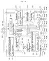
- FIG. 7A illustrates a construction of an RLC AM entity according to a first embodiment of the present invention and FIG. 7B illustrates a block diagram of FIG. 7A in detail.
- the RLC AM entity of the first embodiment is mainly constructed with a transmission module 210, a receiving module 220, and an RLC control module 230.
- the transmission module 210 of the RLC AM entity corresponding to a transmitting side is constructed with a first data processing module 201 converting SDUs transmitted from an upper layer through AM-SAP 207 into PDUs, a transmission data storage module(or transmission buffer) 202 storing the AMD PDUs, and a ciphering module 203 setting the PDUs stored in the transmission buffer 202 as predetermined fields by a control of the RLC control module 230 and ciphering the PDUs.
- the ciphered PDUs are transmitted to an RLC AM entity corresponding to a receiving side through channels DCCH and DTCH.
- the receiving module 220 of the RLC AM entity is constructed with a deciphering module 204 transmitting control PDUs of the ciphered AMD PDUs transmitted through channels DCCH and DTCH from the RLC AM entity corresponding to the transmitting side and deciphering AMD PDUs only, a received data storage module(or receiver buffer) 205 storing the deciphered AMD PDUs, and a second data processing module 206 reassembling the AMD PDUs stored in the received data storage module(or receiver buffer) 205 by SDU unit and then transmitting the AMD PDUs to the upper layer through the AM-SAP 207.
- a deciphering module 204 transmitting control PDUs of the ciphered AMD PDUs transmitted through channels DCCH and DTCH from the RLC AM entity corresponding to the transmitting side and deciphering AMD PDUs only
- a received data storage module(or receiver buffer) 205 storing the deciphered AMD PDUs
- a second data processing module 206 reassembling the AMD
- the transmission buffer 202 in the RLC AM entity processes the data by SDU unit.
- the ciphering module 203 of the RLC AM entity checks a D/C field before the PDUs are ciphered.
- the D/C field check enables AMD PDUs to be ciphered only in the PDUs but control PDUs not to be ciphered.
- the piggybacked status PDU is ciphered but status PDU is transmitted without being ciphered.
- the receiver buffer of the RLC AM entity processes the data by SDU unit.
- FIG. 7B illustrates a block diagram of FIG. 7A in detail.
- the transmission module 210 of the RLC AM entity is constructed with a segmentation/concatenation module 211 carrying out segmentation and concatenation on SDUs stepping down from an upper layer, an RLC header module 212 forming PDUs by adding sequence numbers SN to the segmented and concatenated SDUs, a retransmission buffer/management module 213 storing the header-added PDUs for retransmission and management, a multiplexer(or multiplexing module) 214 outputting one of output signals of the RLC header module 212 and the retransmission buffer/management module 213, a transmission buffer(or storage module) 215 storing the PDUs outputted from the multiplexer 214 as not ciphered, a set fields block(or set fields module) 216 setting a D/C field and other fields as proper values, and a ciphering module 217 ciphering the PDUs outputted from the set fields block 216 and transmitting the ciphered PDUs
- the ciphering module 217 checks header D/C fields of the AMD PDUs before ciphering and then ciphers not control PDU but the AMD PDU including piggybacked status PDU only in accordance with values of the D/C fields.
- the ciphering module 217 checks the AMD PDUs. If PAD exists in the AMD PDU, the AMD PDUs are replaced by PDUs of the piggybacked status.
- the receiving module 220 of the RLC AM entity is constructed with a demultiplexing/routing module 221 transmitting control PDU of PDUs received from the transmission module 210 of other entity to the RLC control unit 230 and AMD PDU to a deciphering block 222, a deciphering module 222 deciphering the AMD PDUs, a receiver buffer 223 storing the deciphered AMD PDUs and outputting the stored PDUs by SDU unit, a header/piggybacked information removal module 224 removing the RLC headers and piggybacked information from the PDUs received by the SDU unit, and a reassembly module 225 reassembling the SDUs constructed with the data only and then transmitting them to the upper layer.
- the demultiplex/routing module 221 of the receiving module 220 checks whether the transmitted PDUs are the control PDU or the AMD PDU through the D/C field check.
- the receiver buffer 223 transmits the stored PDUs to the upper layer by the SDU unit.
- the first embodiment of the present invention introduces a new RLC AM entity enabling to overcome the problems of the ciphering/deciphering of the related art.
- the transmission module 210 of the entity performs the ciphering step as a final stage after the set fields block and the receiving module 220 of the entity performs the deciphering step as an initial stage before the receiver buffer.
- one logical channel or two may be applied to the RLC AM entity.
- UTRAN When two logical channels are applied, UTRAN enables to instruct that the first logical channel is used for data PDUs and the second logical channel is used for control PDUs.
- the instruction fails to be given by the UTRAN, the data and control PDUs may be sent through one of the two channels, the instruction of the logical channel mapping is signaled by RRC.
- SDUs stepping downward from the upper layers are segmented and concatenated through the segmentation/concatenation module 211.
- the SDUs are segmented and concatenated into/by PDUs having fixed lengths.
- the length of the PDU is determined in a radio bearer reassembly and a semi-static value changeable through bearer reassembly by RRC.
- the SDUs are inputted to the RLC header module 212 where headers including sequence numbers are added to the SDUs so as to form PDUs.
- the PDUs to which the headers are added are immediately transmitted to the multiplexer 214 and simultaneously stored in the retransmission buffer/management module 213.
- information bits of the length indicator and extension are inserted into the initial part of the PDU including the boundaries of the SDUs.
- the multiplex 214 outputs one of outputs of the RLC header module 212 and the retransmission buffer/management module 213.
- the multiplexer 214 determines what PDUs are selected and when the PDUs will be transmitted to the MAC.
- the PDUs are transmitted through the functions of completing the RLC PDU headers and replacing the padding by the piggybacked status information.
- the PDUs transmitted through the multiplexer 214 are stored in the transmission buffer 215 as a not-ciphered state, and the PDUs stored in the transmission buffer 215 are then transmitted to the set fields block 216.
- the D/C field and other fields are set as proper values and the AMD PDU us replaced by the piggybacked status PDU if PAD exists in the AMD PDU.
- the ciphering module 217 ciphers the AMD PDUs outputted from the set fields block 216 and then transmits the ciphered AMD PDUs toward another RLC AM entity corresponding to the receiving side.
- the header D/C fields of the AMD PDUs are checked.
- the ciphering is carried out on the AMD PDUs including the piggybacked status PDU only. But, the ciphering is not carried out on the control PDUs such as status, reset, reset acknowledgement PDU(reset ACK PDU).
- the padding is replaced by the control information so as to increase transmission efficiency and enable faster message exchange between the peer and peer entities.
- the piggybacked control information fails to be saved by any retransmission buffer.
- the piggybacked control information is included in the piggybacked status PDU, which is subsequently included in the AMD PDU.
- the piggybacked status PDUs have variable sizes so as to be matched with total amount of free space in the AMD PDU.
- the retransmission buffer 213 receives acknowledged signals from the receiving side, instructs the retransmission of the PDUs, and instructs when one PDU is deleted from the retransmission buffer 213.
- the receiving module receives the AMD PDUs through one of the logical channels from the MAC sub-layer.
- the RLC PDUs are extended to separated PDUs and potential piggybacked status information is extracted.
- the PUs are located in the receiver buffer 205 until a complete SDU is received.
- the receiver buffer 205 requests retransmission of corresponding PDUs by sending negative acknowledgement signals to the peer entity(or RLC entity corresponding to the transmitting party).
- the demultiplex/routing module 221 of the receiving module 220 judges whether the transmitted PDUs are the control PDUs or the AMD PDUs through the D/C field check.
- the demultiplex/routing module 221 transmits the received PDUs, if they are the control PDUs, to the RLC control module 230 or to the deciphering module 222 if they are the AMD PDUs.
- the deciphered AMD PDUs are stored in the receiver buffer/retransmission management module 223. And, the receiver buffer/retransmission management module 223 transmits the received PDUs to the upper module by the SDU unit.
- the header and piggybacked information removal module 224 constructs the SDUs comprising pure data by removing the RLC headers and piggybacked information from the PDUs received by the SDU unit.
- the SDUs are transmitted to the upper layer.
- the reassembly module 225 reassembles the PDUs constructed with the pure data into the SDUs and then transmits the SDUs to the upper layer through the AM-SAP 207.
- acknowledgement signals are passed to the transmission module of the RLC entity corresponding to the transmitting side.
- the ciphering of the PDUs are performed in the final stage of the transmitting module and the PDUs are deciphered in the initial stage of the receiving module. Therefore, the PDUs are stored in the transmission and receiver buffers as a not-ciphered state. Thus, the transmission and receiver buffers need no deciphering function when storing the PDUs therein. Consequently, the time taken for processing the PDUs in the RLC layers is reduced since the transmission buffer, set fields block, and receiver buffer require not ciphering and deciphering functions.
- the piggybacked status PDUs having difficulty in processing are processed with ease in the present invention.
- the not-ciphered i.e. deciphered
- PDUs are stored in the receiver buffer, it is able to sufficiently make use of other functions of the RLC processed by the SDU unit. Therefore, data processing speed in the RLC is increased as well as the AM entity enables to operate more stably.
- control PDU but the AMD PDUs are ciphered only by checking the D/C field when the PDUs are ciphered, thereby enabling to reduce the time taken for processing the PDUs.
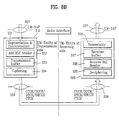
- FIG. 8A illustrates a construction of an RLC UM entity according to a second embodiment of the present invention
- FIG. 8B illustrates a block diagram of FIG. 8A in detail.
- the RLC UM entity shown in FIG. 8A and FIG. 8B is characterized in that a transmitting module performing the ciphering step after a transmission buffer and a receiving module performing the deciphering step before a receiver buffer.
- a transmitting module 310 of the RLC UM entity in FIG. 8A is constructed with a first data processing module 301 converting SDUs stepping down from an upper layer into transmittable PDUs, a transmission data storing module(or transmission buffer) 302 storing the PDUs, and a ciphering module 303 ciphering the PDUs stored in the transmission data storing module 305 and transmitting the ciphered PDUs to an RLC UM entity corresponding to a receiving side.
- a receiving module 320 of the RLC UM entity in FIG. 8A is constructed with a deciphering module 304 the PDUs transmitted from the RLC UM entity corresponding to the transmitting side, a received data storing module(or receiver buffer) 305 storing the deciphered PDUs, and a second data processing module 306 transmitting the PDUs stored in the received data storing module 305 to the upper layer through an UM-SAP 307 by SDU and SDU units.
- the received signal processing module constructs the SDU stepping down from the upper layer with PDUs and adds headers to the PDUs.
- the transmission buffer stores the UMD PDU.
- the ciphering module ciphers the UMD PDU stored in the transmission buffer.
- the ciphered UMD PDU is transmitted to another UM entity corresponding to the receiving side through channels such as CCCH, DCCH, DTCH, SHCCH, and CTCH.
- the RLC entity transfers the UMD PDUs to MAC through the channels.
- the channels CCCH and SHCCH are used for UM only on down-link. What channels are used depends on whether the upper layer is located on a control plane or a user plane.
- the channels CCCH, DCCH, and SHCCH are used. If the upper layer is located on the user plane, the channels CTCH and DTCH are used.
- the transmission buffer processes data by the SDU unit.
- the deciphering part 307 deciphers the received UMD PDU and the receiver buffer 308 stores the deciphered UMD PDU.
- An RLC header removing part 309 removes the RLC header from the UMD PDU stored in the receiver buffer 308.
- a reassembling part 310 reassembles the UMD PDU outputted from the RLC header removing part 309 into the RLC SDUs an then transmits the reassembled UMD SDUs to the upper layer through the UM-SAP.
- the receiver buffer of the RLC UM entity processes data by the SDU unit.
- FIG. 8B illustrates a block diagram of FIG. 8A in detail.
- the transmitting module 310 of the RLC AM entity is constructed with a segmentation/concatenation module 331 carrying out segmentation and concatenation on the SDUs transmitted from the upper layer through the UM-SAP 307, an RLC header module 332 forming PDUs by adding sequence numbers SN to the segmented data, a transmission data storing module(or transmission buffer) 333 storing the PDUs, and a ciphering module 334 ciphering the PDUs stored in the transmission data storing module 333 and transmitting the ciphered PDUs to the RLC UM entity corresponding to the receiving side.
- a segmentation/concatenation module 331 carrying out segmentation and concatenation on the SDUs transmitted from the upper layer through the UM-SAP 307
- an RLC header module 332 forming PDUs by adding sequence numbers SN to the segmented data
- a transmission data storing module(or transmission buffer) 333 storing the PDUs
- the segmentation/concatenation module 331 and the RLC header module 332 in FIG. 8B are equivalent to the first data processing module 301 in FIG. 8A.
- the receiving module 320 is constructed with a deciphering module 335 deciphering the PDUs transmitted from the RLC UM entity corresponding to the transmitting side, a received data storing module(or receiver buffer) 337 storing the deciphered PDUs, an RLC header removing module 336 removing the RLC headers from the PDUs, and a reassembly module 338 forming the SDUs by reassembling the PDUs outputted from the RLC header removing module 337 and then transmitting them to the upper layer through the UM-SAP 307.
- a deciphering module 335 deciphering the PDUs transmitted from the RLC UM entity corresponding to the transmitting side
- a received data storing module(or receiver buffer) 337 storing the deciphered PDUs
- an RLC header removing module 336 removing the RLC headers from the PDUs
- a reassembly module 338 forming the SDUs by reassembling the PDUs
- the RLC header removing module 336 and the reassembling module 338 in FIG. 8B are equivalent to the second data processing module 306 in FIG. 8A.
- the SDUs transmitted from the upper layer through the UM-SAP 307 are segmented and concatenated in the segmentation/concatenation module 331 and then inputted to the RLC header module 332.
- the TLC header module 332 forms the PDUs by adding headers including sequence numbers SN to the segment data from the segmentation/concatenation module 331.
- the transmission buffer 333 stores the PDUs and then outputs the PDUs in PDU unit. Meanwhile, the ciphering module 334 ciphers the PDUs stored in the transmission buffer 333 and then transmits the ciphered PDUs to the RLC UM entity corresponding to the receiving side.
- the deciphering module 335 of the RLC UM entity corresponding to the receiving side deciphers the PDUs transmitted through the channels and the receiver buffer 337 stores the deciphered PDUs. Then, the receiver buffer 337 outputs the PDUs by the SDU unit and the RLC header removing module 336 removes the headers from the PDUs.
- the reassembling module 338 forms the SDUs by reassembling the PDUs outputted from the RLC header removing module 336 and then transmits the SDUs to the upper layer.
- FIG. 8C illustrates a block diagram of another application of the RLC UM entity.
- the order of the first data processing module 301 and transmission data storing module 302 in FIG. 8A is inversed.
- a transmitting module 310 of the RLC UM entity according to FIG. 8C includes a received data storing module 302 storing SDUs stepping down from the upper layer, a first data processing module 301 converting the SDUs stored in the received data storing module into UMD PDUs, and a ciphering module ciphering the UMD PDUs stored in the transmission data storing module 302 and then transmitting the ciphered UMD PDUs to the RLC UM entity corresponding to the receiving side.
- FIG. 8D is a detailed block diagram of FIG. 8C.
- the data transmission module includes a transmission data storage module 333 for storing service data units from an upper layer, a segmentation and concatenation module 331 that acts as a transmission data reassembly module for reassembling protocol data units of the RLC layer, an RLC header module 332 for adding header of the RLC layer to the PDUs reassembled by the segmentation and concatenation module 331, and a ciphering module 334 ciphering the header-added PDUs and transmitting the ciphered PDUs to a lower layer.
- FIG. 8B The construction of FIG. 8B is identical to that of 8D except that the transmission data module 333 is switched to the segmentation and concatenation module 331. Therefore, the detailed description of 8D will be skipped hereof.
- the SDUs are transmitted to the transmitting module through the UM-SAP from the upper layer
- the ciphered PDUs are transmitted toward the RLC entity corresponding to the receiving side through the channels DTCH, DCCH, CCCH, SHCCH, and CTCH from the transmitting module
- the ciphered PDUs transmitted from the RLC UM entity corresponding to the transmitting side enter the receiving module through the channels DTCH, DCCH, CCCH, SHCCH, and CTCH
- the PDUs outputted from the second data processing module are transmitted to the upper layer through the UM-SAP.
- the first data processing module includes a segmentation/concatenation module 331 carrying out segmentation and concatenation on the SDUs transmitted from the upper layer through the UM-SAP 307 and an RLC header module 332 forming PDUs by adding sequence numbers SN to the segmented data.
- the ciphering and deciphering steps are arranged in a manner that the not-ciphered SDUs are stored in the transmission buffer 333 and the not-ciphered PDUs in the receiver buffer 336.
- the transmission buffer 333 and the receiver buffer 336 need no deciphering function.
- the RLC UM entity according to the second embodiment of the present invention has the advantages or effects as follows.
- the ciphering step is arranged as the final processing step in the transmitting module of the entity and the deciphering step is arranged as the initial processing step in the receiving module, thereby enabling to transmit and receive PDUs more efficiently.
- the already-deciphered PDUs are stored in the receiver buffer, thereby enabling to transmit UMD PDUs to the upper layer more effectively and faster.
- the transmission and receiver buffers require no deciphering function, thereby enabling to reduce data processing time on using other RLC functions carrying out data processing by SDU unit such as SDU discard function.
Landscapes
- Engineering & Computer Science (AREA)
- Computer Networks & Wireless Communication (AREA)
- Signal Processing (AREA)
- Computer Security & Cryptography (AREA)
- Computer Hardware Design (AREA)
- Computing Systems (AREA)
- General Engineering & Computer Science (AREA)
- Mobile Radio Communication Systems (AREA)
- Communication Control (AREA)
- Transmitters (AREA)
Abstract
Description
- The present invention relates to a radio communication system having a radio link control (RLC) layer and a data processing method in the same.
- Many efforts are made to develop and study communication technology admitting multimedia access without spatiotemporal limitations.
- The developments of digital data processing and transmission technology enable to realize a real-time global data communication system using satellites and the combined wireless and wire communications lately.
- Thus, such developments of digital data processing and transmission technology enables to gain access to information freely regardless of voice communication, still image based on networks, real-time transmission of moving pictures through wire or wireless communication means.
- IMT-2000 will be one of them.
- An RLC layer is the second layer of 3GPP as a protocol layer controlling data links corresponding to the second layer of OSI 7-layered model. And, RLC species used in 3GPP are mainly divided into Tr(transparent) mode to which no RLC header is added and NTR(non-transparent mode) to which RLC header is added.
- NTr mode is subdivided into UM mode(unacknowledged mode) having no ACK(acknowledgement) signal from a receive stage and AM mode(acknowledged mode) having an ACK signal from the receive stage.
- Therefore, RLC presently uses three modes of Tr, UM, and AM, in which AM entity structure is shown FIG. 1.
- FIG. 1 illustrates a block diagram of RLC AM entity structure according to a related art. Referring to FIG. 1, in AM entity of a transmitting side, segmentation and concatenation are carried out through a
block 101 so as to change SDUs(service data units) stepping down from an upper layer into uniform-sized protocol data units (PDUs) and headers containing sequence numbers SN are added to PDUs through ablock 102. - PDU to which the header is added is transmitted downward as well as stored in a
retransmission buffer 103 for a later use such as retransmission which may occur in future. The PDU flown down through amultiplexer 104 under goes a ciphering through ablock 105 for data security and then is temporarily stored in atransmission buffer 106 so as to be transmitted to aset fields block 107. - In the
set field block 107, other fields such as DC and poll field and the like except the sequence number SN of the RLC header are set and then transmitted to another AM entity corresponding to a receiving side. - Such a PDU carrying data stepping down from an upper layer is called AMD(AM data) PDU of which structure is shown in FIG. 2. FIG. 2 illustrates a structure of AMD PDU.
- In this case, format of the AMD PDU is constructed with a header and LI(length indicator) group, data, and PAD(padding) or piggybacked status PDU.
- The header includes a sequence number as a field representing the order numbers of the respective AMP PDUs, an 1-bit D/C field informing whether the corresponding AMD PDU carries data information or control information, an 1-bit polling field(P field) asking a receiving side of a status report, a 2-bit HE(header extension) field informing whether next data are data or LI and E bit, and an 1-bit E(extension) field informing whether a next field is data or LI and E bit.
- The LI part in the AMD PDU is constructed with LI and E bit, in which LI is a filed indicating boundaries of the respective SDUs when the PDU includes a plurality of SDUs. Each LI represents an octet count from the first octet of the data part to the last octet of the respective SDUs, and the respective LIs for the SDUs included in the PDU are called the LI group.
- The data part including at least one SDU is a field corresponding to the SDUs stepping down from the upper layer. As the size of the data part is variable, padding is carried out so as to octet-align the sizes of the entire PDUs.
- The foregoing ciphering is carried out on the AMD PDU. In this case, the first two octets, which are the header part, including the sequence number are not ciphered. Thus, the rest thereof is ciphered.
- In the AM entity, control PDU exists as well as the AMD PDU. The control PDU includes a status PDU carrying status information, reset PDU resetting AM entity, and reset ACK PDU informing the acknowledgement(ACK) of the reset PDU.
- FIG. 3 illustrates a structure of status PDU, and FIG. 4 illustrates a structure of reset ACK PDU for explaining the reset and the reset ACK PDU.
- The control PDUs, which are generated from the RLC control unit, are transmitted to the set fields block without undergoing the ciphering, set D/C and PDU type fields, and then transmitted to RLC AM entity corresponding to the receiving side.
- Namely, in the
set fields block 107, a D/C field is set as 1 for the AMD PDU but as 0 for the control PDU. When there is a vacancy in the AMD PDU failing filled up with data, padding(PAD) is carried out thereon. - When there is such a PAD in the AMD PDU, the
set fields block 107 enables to transmit status PDU instead of PAD so as to increase the data transmission efficiency. In this case, the status PDU is called piggybacked status PDU. - As mentioned in the above explanation, the RLC AM entity corresponding to the receiving side receiving PDU of the AM entity which is transmitted from the RLC AM entity corresponding to the transmitting side processing the AMD PDU in a manner as follows.
- First, a demultiplex/
routing part 108 checks the D/C field. If a D/C field value is 0, the control PDU is instantly sent upward to theRLC control unit 100 since '0' corresponds to the control PDU. If the D/C field value is 1, the AMD PDU is instantly sent upward to thereceiver buffer 109 since '1' corresponds to the AMD PDU. - The RLC AM entity enables to use one or two logical channels for one radio bearer set-up.
- In FIG. 1, solid and dotted lines indicate the cases of using one or two logical channels, respectively.
- As shown in FIG. 1, data and control channels are determined when two logical channels are used. Therefore, the AMD PDU is immediately transmitted to the
receiver buffer 109 and the control PDU is transmitted to theRLC control unit 100 via the demultiplex/routing part 108. - The
receiver buffer 109, which checks the receiving statuses of the respective AMD PDUs, asking the transmitting side of retransmission of the not-received PDU by sending an NACK signal to the transmitting side when there is not-received AMD PDU. - The PDUs having been stored in the
receiver buffer 109 are stored until all the PDUs constructing a complete SDU are thoroughly received. After receiving all the corresponding PDUs, thereceiver buffer 109 sends upward the PDUs by SDU unit. - Thereafter, the PDUs are deciphered by a deciphering
part 110, and data are extracted only by removing RLC headers and piggybacked information from the respective PDUs in ablock 111. Thus, SDU is constructed with the pure data through theblock 111. - Subsequently, the SDU is sent upward to an upper layer through a
reassembly part 112. - Unfortunately, the related art has problems in transmitting the AMD PDU as follows.
- In order for the transmitting side to transmit the piggybacked status PDU, the set fields block checks whether there exists PAD which the piggybacked status PDU enters in the AMD PDU. When such a PAD the piggybacked status PDU enters exists in the AMD PDU, the PAD has to be replaced by the piggybacked status PDU.
- Meanwhile, as the AMD PDU has been ciphered already, the ciphered AMD PDU has to be deciphered in the set fields block in order to know the exact location of the PAD and whether the PAD exists.
- Moreover, the ciphered AMD PDU should be deciphered to transmit the AMD PDU, whereby deciphering/ciphering has to be carried out in the set fields block unnecessarily.
- Further, as mentioned in the above explanation, RLC AM entity corresponding to the receiving side has to be sent upward from the receiver buffer to the upper layer when the PDUs are sent upward.
- In this case, having been ciphered already by the transmitting side, the PDUs stored in the receiver buffer have to be deciphered in order to know whether each of the PDUs belongs to which SDU.
- Therefore, the receiver buffer needs a function of deciphering the PDU unnecessarily as well.
- As mentioned in the foregoing description, the repeated ciphering/deciphering reduces processing speed and efficiency of the AMD PDU data and further degrades the system performance.
- In functions of the RLC, there is an SDU discard function used for preventing overflow of a buffer.
- When this function is used, PDUs corresponding to the SDU to be discarded from the transmitting buffer and the receiver buffer have to be discarded. As all the ciphered PDUs are stored in the transmitting and receiver buffers, the transmitting and receiver buffers require the deciphering function commonly.
- FIG. 5 illustrates a construction of RLC UM entity according to a related art.
- Referring to FIG. 5, segmentation and concatenation are carried out through a
block 122 so as to change SDUs(service data units) stepping down from an upper layer through UM-SAP into uniform-sized protocol data units(PDUs). - Subsequently, a
ciphering part 123 ciphers the PDUs for data security. Then, anRLC header part 124 adds headers containing sequence numbers SN to the PDUs so as to construct UMD(unacknowledged mode data) PDU. - A
transmission buffer 125 stores and transmits the UMD PDU to RLC UM entity corresponding to a receiving side. - In an RLC layer, exist UMD PDU (unacknowledged PDU) used when an ACK signal to a transmitting side is not necessary after receiving PDU from a receiving side and AMD PDU(acknowledged PDU) used when the ACK signal is necessary.
- As shown in FIG. 6, format of the AMD PDU is constructed with a header and LI(length indicator) group, data, and PAD(padding).
- The header includes a sequence number as a field representing the order numbers of the respective PDUs and an 1-bit E(extension) field informing whether a next field is data, the LI or extension bit.
- The data part including at least one SDU is a field corresponding to the SDUs stepping down from the upper layer. As the size of the data part is variable, padding is carried out so as to octet-align the sizes of the entire PDUs.
- In the same manner as the AMD PDU, the LI part in the UMD PDU is constructed with LI and E bit, in which LI is a filed indicating boundaries of the respective SDUs when the PDU includes a plurality of SDUs. Each LI represents an octet count from the first octet of the data part to the last octet of the respective SDUs, and the respective LIs for the SDUs included in the PDU are called the LI group.
- As mentioned in the above explanation, a structure of the UMD PDU is equal to that in FIG. 6, in which the first octet is the header including the sequence number and the header is not ciphered. Thus, the rest thereof is ciphered.
- RLC UM entity stores the transmitted UMD PDU in the
receiver buffer 130. When all the PDUs constructing a complete SDU are thoroughly received, the stored PDUs are transmitted to ablock 129 by SDU unit. - Thereafter, the headers of the PDUs are removed in the
block 129 and the PDUs are deciphered by a decipheringpart 128. Thus, the deciphered PDUs are transmitted to an upper layer through areassembly part 126. - Unfortunately, the related art has problems in transmitting the UMD PDU using RLC UM entity as follows.
- As mentioned in the foregoing description, the PDUs are sent to the upper layer from the receiver buffer by SDU unit. In this case, the PDUs have been ciphered already. Besides, deciphering has to be carried out in order to know that each PDU belongs to which SDU.
- Therefore, the receiver buffer needs a deciphering function unnecessarily.
- In functions of the RLC, there is an SDU discard function used for preventing overflow of a buffer. When this function is used, PDUs corresponding to the SDU to be discarded from the transmitting and receiver buffers have to be discarded.
- As all the ciphered PDUs are stored in the transmitting and receiver buffers, the transmitting and receiver buffers require the deciphering function commonly.
- Accordingly, the present invention is directed to a radio communication system having an RLC layer and data processing method in the same that substantially obviates one or more problems due to limitations and disadvantages of the related art.
- An object of the present invention is to provide a radio communication having an RLC layer enabling to perform the transmission and reception of PDU more effectively.
- Another object of the present invention is to provide a data processing method in a radio communication system having an RLC layer enabling to process PDU fast in an RLC entity.
- A data transmission module of a radio communication system having an RLC entity according to the present invention carries out a ciphering step as a final processing step after a transmission buffer. And, a data receiving module of a radio communication system having the RLC entity carries out a deciphering step as a first processing step before a receiver buffer. An RLC entity according to the present invention includes an RLC AM entity and an RLC UM entity.
- Additional advantages, objects, and features of the invention will be set forth in part in the description which follows and in part will become apparent to those having ordinary skill in the art upon examination of the following or may be learned from practice of the invention. The objectives and other advantages of the invention may be realized and attained by the structure particularly pointed out in the written description and claims hereof as well as the appended drawings.
- To achieve these objects and other advantages and in accordance with the purpose of the invention, as embodied and broadly described herein, a data transmission module according to the present invention includes a transmission data storing module storing PDUs corresponding to SDUs transmitted from a first upper layer and outputting the stored PDUs by SDU unit, a ciphering module ciphering the PDUs stored in the transmission data storing module and transmitting the ciphered PDUs to a second RLC entity, a deciphering module deciphering ciphered PDUs transmitted from a first RLC entity, and a received data storing module storing the deciphered PDUs and outputting the PDUs toward a second upper layer by SDU unit.
- In another aspect of the present invention, in an RLC entity having a transmission buffer, a data processing method in the RLC entity includes the steps of storing SDUs stepping down from a first upper layer in the transmission buffer in PDUs, ciphering the PDUs stored in the transmission buffer, and transmitting the ciphered PDUs to a second RLC entity corresponding to a receiving side.
- In other aspect of the present invention, in an RLC entity having a receiver buffer, a data processing method in the RLC entity includes the steps of receiving and deciphering PDUs received from a first RLC entity corresponding to a transmitting side, storing the deciphered PDUs in the receiver buffer, and reassembling the PDUs stored in the receiver buffer and then transmitting the reassembled data to a second upper layer.
- It is to be understood that both the foregoing general description and the following detailed description of the present invention are exemplary and explanatory and are intended to provide further explanation of the invention as claimed.
- The accompanying drawings, which are included to provide a further understanding of the invention and are incorporated in and constitute a part of this application, illustrate embodiment(s) of the invention and together with the description serve to explain the principle of the invention. In the drawings:
- FIG. 1 illustrates a block diagram of a radio communication system having an RLC AM entity according to a related art;
- FIG. 2 illustrates a structure of AMD PDU;
- FIG. 3 illustrates a structure of status PDU;
- FIG. 4 illustrates a structure of reset ACK PDU for explaining the reset and the reset ACK PDU;
- FIG. 5 illustrates a construction of a radio communication system having an RLC UM entity according to a related art;
- FIG. 6 illustrates a structure of UMD PDU;
- FIG. 7A illustrates a construction of a radio communication system having an RLC AM entity according to a first embodiment of the present invention;
- FIG. 7B illustrates a block diagram of FIG. 7A in detail;
- FIG. 8A illustrates a construction of a radio communication system having an RLC UM entity according to a second embodiment of the present invention;
- FIG. 8B illustrates a block diagram of FIG. 8A in detail;
- FIG. 8C illustrates a block diagram of another application of FIG. 8A; and
- FIG. 8D illustrates a detailed block diagram of FIG. 8C.
-
- Reference will now be made in detail to the preferred embodiments of the present invention, examples of which are illustrated in the accompanying drawings.
- In a data transmission device of a radio communication system having an RLC layer, according to the main feature of the present invention, a transmission data reassembling module reassembles service data units(SDUs) received from an upper layer into protocol data units(PDUs). A header adding module then adds headers of the RLC layer to the PDUs. After that, a transmission data storing module stores the PDUs to which the headers are added. A ciphering module ciphers the PDUs to which the headers are added and then transmits the ciphered PDUs to a lower layer.
- In a data receiving device of a radio communication system having an RLC layer, according to the main feature of the present invention, a deciphering module deciphers ciphered PDUs of an RLC layer transmitted from a transmitting side through a lower layer. A received data storing module then stores the deciphered PDUs. An RLC header removing module removes headers of the RLC layer from the PDUs. A reassembly module reassembles the PDUs outputted from the RLC header removing module in service data units (SDUs) and then transmits them to an upper layer.
- FIG. 7A illustrates a construction of an RLC AM entity according to a first embodiment of the present invention and FIG. 7B illustrates a block diagram of FIG. 7A in detail.
- Referring to FIG. 7A, the RLC AM entity of the first embodiment is mainly constructed with a
transmission module 210, a receivingmodule 220, and anRLC control module 230. - The
transmission module 210 of the RLC AM entity corresponding to a transmitting side is constructed with a firstdata processing module 201 converting SDUs transmitted from an upper layer through AM-SAP 207 into PDUs, a transmission data storage module(or transmission buffer) 202 storing the AMD PDUs, and aciphering module 203 setting the PDUs stored in thetransmission buffer 202 as predetermined fields by a control of theRLC control module 230 and ciphering the PDUs. The ciphered PDUs are transmitted to an RLC AM entity corresponding to a receiving side through channels DCCH and DTCH. - The receiving
module 220 of the RLC AM entity is constructed with adeciphering module 204 transmitting control PDUs of the ciphered AMD PDUs transmitted through channels DCCH and DTCH from the RLC AM entity corresponding to the transmitting side and deciphering AMD PDUs only, a received data storage module(or receiver buffer) 205 storing the deciphered AMD PDUs, and a seconddata processing module 206 reassembling the AMD PDUs stored in the received data storage module(or receiver buffer) 205 by SDU unit and then transmitting the AMD PDUs to the upper layer through the AM-SAP 207. - Preferably, the
transmission buffer 202 in the RLC AM entity processes the data by SDU unit. - And, the
ciphering module 203 of the RLC AM entity checks a D/C field before the PDUs are ciphered. The D/C field check enables AMD PDUs to be ciphered only in the PDUs but control PDUs not to be ciphered. - If the AMD PDU in the RLC AM entity includes piggybacked status PDU, the piggybacked status PDU is ciphered but status PDU is transmitted without being ciphered.
- And, the receiver buffer of the RLC AM entity processes the data by SDU unit.
- FIG. 7B illustrates a block diagram of FIG. 7A in detail.
- Referring to FIG. 7B, the
transmission module 210 of the RLC AM entity is constructed with a segmentation/concatenation module 211 carrying out segmentation and concatenation on SDUs stepping down from an upper layer, anRLC header module 212 forming PDUs by adding sequence numbers SN to the segmented and concatenated SDUs, a retransmission buffer/management module 213 storing the header-added PDUs for retransmission and management, a multiplexer(or multiplexing module) 214 outputting one of output signals of theRLC header module 212 and the retransmission buffer/management module 213, a transmission buffer(or storage module) 215 storing the PDUs outputted from themultiplexer 214 as not ciphered, a set fields block(or set fields module) 216 setting a D/C field and other fields as proper values, and aciphering module 217 ciphering the PDUs outputted from the set fields block 216 and transmitting the ciphered PDUs to the receiving side. - Preferably, the
ciphering module 217 checks header D/C fields of the AMD PDUs before ciphering and then ciphers not control PDU but the AMD PDU including piggybacked status PDU only in accordance with values of the D/C fields. - And, the
ciphering module 217 checks the AMD PDUs. If PAD exists in the AMD PDU, the AMD PDUs are replaced by PDUs of the piggybacked status. - Referring to FIG. 7B, the receiving
module 220 of the RLC AM entity is constructed with a demultiplexing/routing module 221 transmitting control PDU of PDUs received from thetransmission module 210 of other entity to theRLC control unit 230 and AMD PDU to adeciphering block 222, adeciphering module 222 deciphering the AMD PDUs, areceiver buffer 223 storing the deciphered AMD PDUs and outputting the stored PDUs by SDU unit, a header/piggybackedinformation removal module 224 removing the RLC headers and piggybacked information from the PDUs received by the SDU unit, and areassembly module 225 reassembling the SDUs constructed with the data only and then transmitting them to the upper layer. - Preferably, the demultiplex/
routing module 221 of the receivingmodule 220 checks whether the transmitted PDUs are the control PDU or the AMD PDU through the D/C field check. - And, the
receiver buffer 223 transmits the stored PDUs to the upper layer by the SDU unit. - As mentioned in the above description, the first embodiment of the present invention introduces a new RLC AM entity enabling to overcome the problems of the ciphering/deciphering of the related art.
- In the RLC AM entity structure, the
transmission module 210 of the entity performs the ciphering step as a final stage after the set fields block and the receivingmodule 220 of the entity performs the deciphering step as an initial stage before the receiver buffer. - In the following, the steps of processing the AMD PDU in the RLC AM entity according to the first embodiment of the present invention are explained in detail by referring to FIG. 7A and FIG. 7B.
- As shown in FIG. 7A and FIG. 7B, one logical channel or two may be applied to the RLC AM entity.
- When two logical channels are applied, UTRAN enables to instruct that the first logical channel is used for data PDUs and the second logical channel is used for control PDUs.
- If the instruction fails to be given by the UTRAN, the data and control PDUs may be sent through one of the two channels, the instruction of the logical channel mapping is signaled by RRC.
- In aspect of the transmitting
module 210, SDUs stepping downward from the upper layers are segmented and concatenated through the segmentation/concatenation module 211. Namely, the SDUs are segmented and concatenated into/by PDUs having fixed lengths. The length of the PDU is determined in a radio bearer reassembly and a semi-static value changeable through bearer reassembly by RRC. - Subsequently, the SDUs are inputted to the
RLC header module 212 where headers including sequence numbers are added to the SDUs so as to form PDUs. The PDUs to which the headers are added are immediately transmitted to themultiplexer 214 and simultaneously stored in the retransmission buffer/management module 213. - For the purpose of concatenation and padding, information bits of the length indicator and extension are inserted into the initial part of the PDU including the boundaries of the SDUs.
- The
multiplex 214 outputs one of outputs of theRLC header module 212 and the retransmission buffer/management module 213. - Namely, the
multiplexer 214 determines what PDUs are selected and when the PDUs will be transmitted to the MAC. The PDUs are transmitted through the functions of completing the RLC PDU headers and replacing the padding by the piggybacked status information. - The PDUs transmitted through the
multiplexer 214 are stored in thetransmission buffer 215 as a not-ciphered state, and the PDUs stored in thetransmission buffer 215 are then transmitted to the set fields block 216. - In the set fields block 216, the D/C field and other fields are set as proper values and the AMD PDU us replaced by the piggybacked status PDU if PAD exists in the AMD PDU.
- Meanwhile, the
ciphering module 217 ciphers the AMD PDUs outputted from the set fields block 216 and then transmits the ciphered AMD PDUs toward another RLC AM entity corresponding to the receiving side. - In this case, before performing the ciphering, the header D/C fields of the AMD PDUs are checked. In accordance with the value of the D/C field, the ciphering is carried out on the AMD PDUs including the piggybacked status PDU only. But, the ciphering is not carried out on the control PDUs such as status, reset, reset acknowledgement PDU(reset ACK PDU).
- When the piggybacked mechanism is applied thereto, the padding is replaced by the control information so as to increase transmission efficiency and enable faster message exchange between the peer and peer entities. The piggybacked control information fails to be saved by any retransmission buffer.
- The piggybacked control information is included in the piggybacked status PDU, which is subsequently included in the AMD PDU. The piggybacked status PDUs have variable sizes so as to be matched with total amount of free space in the AMD PDU.
- The
retransmission buffer 213 receives acknowledged signals from the receiving side, instructs the retransmission of the PDUs, and instructs when one PDU is deleted from theretransmission buffer 213. - Meanwhile, the receiving module receives the AMD PDUs through one of the logical channels from the MAC sub-layer.
- The RLC PDUs are extended to separated PDUs and potential piggybacked status information is extracted. The PUs are located in the
receiver buffer 205 until a complete SDU is received. Thereceiver buffer 205 requests retransmission of corresponding PDUs by sending negative acknowledgement signals to the peer entity(or RLC entity corresponding to the transmitting party). - Namely, when the PDUs are received through the foregoing steps from the
transmission module 210 of other entity, the demultiplex/routing module 221 of the receivingmodule 220 judges whether the transmitted PDUs are the control PDUs or the AMD PDUs through the D/C field check. - The demultiplex/
routing module 221 transmits the received PDUs, if they are the control PDUs, to theRLC control module 230 or to thedeciphering module 222 if they are the AMD PDUs. - In this case, the deciphered AMD PDUs are stored in the receiver buffer/
retransmission management module 223. And, the receiver buffer/retransmission management module 223 transmits the received PDUs to the upper module by the SDU unit. - Namely, the header and piggybacked
information removal module 224 constructs the SDUs comprising pure data by removing the RLC headers and piggybacked information from the PDUs received by the SDU unit. - After the headers are removed from the PDUs and the PDUs are reassembled into one SDU, the SDUs are transmitted to the upper layer.
- Namely, the
reassembly module 225 reassembles the PDUs constructed with the pure data into the SDUs and then transmits the SDUs to the upper layer through the AM-SAP 207. - Meanwhile, the acknowledgement signals are passed to the transmission module of the RLC entity corresponding to the transmitting side.
- As mentioned in the above description, in the AM entity of the present invention, the ciphering of the PDUs are performed in the final stage of the transmitting module and the PDUs are deciphered in the initial stage of the receiving module. Therefore, the PDUs are stored in the transmission and receiver buffers as a not-ciphered state. Thus, the transmission and receiver buffers need no deciphering function when storing the PDUs therein. Consequently, the time taken for processing the PDUs in the RLC layers is reduced since the transmission buffer, set fields block, and receiver buffer require not ciphering and deciphering functions.
- Moreover, the piggybacked status PDUs having difficulty in processing are processed with ease in the present invention.
- Further, as the not-ciphered, i.e. deciphered, PDUs are stored in the receiver buffer, it is able to sufficiently make use of other functions of the RLC processed by the SDU unit. Therefore, data processing speed in the RLC is increased as well as the AM entity enables to operate more stably.
- More further, not the control PDU but the AMD PDUs are ciphered only by checking the D/C field when the PDUs are ciphered, thereby enabling to reduce the time taken for processing the PDUs.
- An RLC UM(unacknowledged mode) entity and its operation according to a second embodiment of the present invention are explained in the following description by referring to FIG. 8A and FIG. 8B.
- FIG. 8A illustrates a construction of an RLC UM entity according to a second embodiment of the present invention and FIG. 8B illustrates a block diagram of FIG. 8A in detail.
- The RLC UM entity shown in FIG. 8A and FIG. 8B is characterized in that a transmitting module performing the ciphering step after a transmission buffer and a receiving module performing the deciphering step before a receiver buffer.
- A transmitting
module 310 of the RLC UM entity in FIG. 8A is constructed with a firstdata processing module 301 converting SDUs stepping down from an upper layer into transmittable PDUs, a transmission data storing module(or transmission buffer) 302 storing the PDUs, and aciphering module 303 ciphering the PDUs stored in the transmissiondata storing module 305 and transmitting the ciphered PDUs to an RLC UM entity corresponding to a receiving side. - A receiving
module 320 of the RLC UM entity in FIG. 8A is constructed with adeciphering module 304 the PDUs transmitted from the RLC UM entity corresponding to the transmitting side, a received data storing module(or receiver buffer) 305 storing the deciphered PDUs, and a seconddata processing module 306 transmitting the PDUs stored in the receiveddata storing module 305 to the upper layer through an UM-SAP 307 by SDU and SDU units. - Regarding the transmitting
module 310 of the UM entity, the received signal processing module constructs the SDU stepping down from the upper layer with PDUs and adds headers to the PDUs. The transmission buffer stores the UMD PDU. The ciphering module ciphers the UMD PDU stored in the transmission buffer. - The ciphered UMD PDU is transmitted to another UM entity corresponding to the receiving side through channels such as CCCH, DCCH, DTCH, SHCCH, and CTCH. In this case, the RLC entity transfers the UMD PDUs to MAC through the channels. The channels CCCH and SHCCH are used for UM only on down-link. What channels are used depends on whether the upper layer is located on a control plane or a user plane.
- If the upper layer is located on the control plane, the channels CCCH, DCCH, and SHCCH are used. If the upper layer is located on the user plane, the channels CTCH and DTCH are used.
- Besides, the transmission buffer processes data by the SDU unit.
- Regarding the receiving module of the RLC UM entity, when the ciphered UMD PDU is received from another UM entity corresponding to the transmitting side through one of the logical channels, the deciphering
part 307 deciphers the received UMD PDU and thereceiver buffer 308 stores the deciphered UMD PDU. - An RLC header removing part 309 removes the RLC header from the UMD PDU stored in the
receiver buffer 308. A reassemblingpart 310 reassembles the UMD PDU outputted from the RLC header removing part 309 into the RLC SDUs an then transmits the reassembled UMD SDUs to the upper layer through the UM-SAP. - Moreover, the receiver buffer of the RLC UM entity processes data by the SDU unit.
- FIG. 8B illustrates a block diagram of FIG. 8A in detail.
- Referring to FIG. 8B, the transmitting
module 310 of the RLC AM entity is constructed with a segmentation/concatenation module 331 carrying out segmentation and concatenation on the SDUs transmitted from the upper layer through the UM-SAP 307, anRLC header module 332 forming PDUs by adding sequence numbers SN to the segmented data, a transmission data storing module(or transmission buffer) 333 storing the PDUs, and aciphering module 334 ciphering the PDUs stored in the transmissiondata storing module 333 and transmitting the ciphered PDUs to the RLC UM entity corresponding to the receiving side. - The segmentation/
concatenation module 331 and theRLC header module 332 in FIG. 8B are equivalent to the firstdata processing module 301 in FIG. 8A. - Referring to FIG. 8B, the receiving
module 320 is constructed with adeciphering module 335 deciphering the PDUs transmitted from the RLC UM entity corresponding to the transmitting side, a received data storing module(or receiver buffer) 337 storing the deciphered PDUs, an RLCheader removing module 336 removing the RLC headers from the PDUs, and areassembly module 338 forming the SDUs by reassembling the PDUs outputted from the RLCheader removing module 337 and then transmitting them to the upper layer through the UM-SAP 307. - The RLC
header removing module 336 and thereassembling module 338 in FIG. 8B are equivalent to the seconddata processing module 306 in FIG. 8A. - In the following, a series of the steps of transmitting and receiving the UMD PDU in the RLC UM entity according to the second embodiment of the present invention are explained in detail by referring to FIG. 8B.
- The SDUs transmitted from the upper layer through the UM-
SAP 307 are segmented and concatenated in the segmentation/concatenation module 331 and then inputted to theRLC header module 332. - The
TLC header module 332 forms the PDUs by adding headers including sequence numbers SN to the segment data from the segmentation/concatenation module 331. - The
transmission buffer 333 stores the PDUs and then outputs the PDUs in PDU unit. Meanwhile, theciphering module 334 ciphers the PDUs stored in thetransmission buffer 333 and then transmits the ciphered PDUs to the RLC UM entity corresponding to the receiving side. - And, the
deciphering module 335 of the RLC UM entity corresponding to the receiving side deciphers the PDUs transmitted through the channels and thereceiver buffer 337 stores the deciphered PDUs. Then, thereceiver buffer 337 outputs the PDUs by the SDU unit and the RLCheader removing module 336 removes the headers from the PDUs. - The
reassembling module 338 forms the SDUs by reassembling the PDUs outputted from the RLCheader removing module 336 and then transmits the SDUs to the upper layer. - FIG. 8C illustrates a block diagram of another application of the RLC UM entity.
- Referring to FIG. 8C, the order of the first
data processing module 301 and transmissiondata storing module 302 in FIG. 8A is inversed. - A transmitting
module 310 of the RLC UM entity according to FIG. 8C includes a receiveddata storing module 302 storing SDUs stepping down from the upper layer, a firstdata processing module 301 converting the SDUs stored in the received data storing module into UMD PDUs, and a ciphering module ciphering the UMD PDUs stored in the transmissiondata storing module 302 and then transmitting the ciphered UMD PDUs to the RLC UM entity corresponding to the receiving side. - FIG. 8D is a detailed block diagram of FIG. 8C.
- Referring to FIG. 8D, the data transmission module includes a transmission
data storage module 333 for storing service data units from an upper layer, a segmentation andconcatenation module 331 that acts as a transmission data reassembly module for reassembling protocol data units of the RLC layer, anRLC header module 332 for adding header of the RLC layer to the PDUs reassembled by the segmentation andconcatenation module 331, and aciphering module 334 ciphering the header-added PDUs and transmitting the ciphered PDUs to a lower layer. - The construction of FIG. 8B is identical to that of 8D except that the
transmission data module 333 is switched to the segmentation andconcatenation module 331. Therefore, the detailed description of 8D will be skipped hereof. - The construction of a
receiving module 320 is equal to that of FIG. 8A, of which explanation will be skipped hereof. - Regarding FIG. 8C, as is the case in FIG. 8A, the SDUs are transmitted to the transmitting module through the UM-SAP from the upper layer, the ciphered PDUs are transmitted toward the RLC entity corresponding to the receiving side through the channels DTCH, DCCH, CCCH, SHCCH, and CTCH from the transmitting module, the ciphered PDUs transmitted from the RLC UM entity corresponding to the transmitting side enter the receiving module through the channels DTCH, DCCH, CCCH, SHCCH, and CTCH, and the PDUs outputted from the second data processing module are transmitted to the upper layer through the UM-SAP.
- Regarding FIG. 8C, as is the case in FIG. 8A, the first data processing module includes a segmentation/
concatenation module 331 carrying out segmentation and concatenation on the SDUs transmitted from the upper layer through the UM-SAP 307 and anRLC header module 332 forming PDUs by adding sequence numbers SN to the segmented data. - As mentioned in the foregoing description, in the RLC UM entity according to the second embodiment of the present invention, the ciphering and deciphering steps are arranged in a manner that the not-ciphered SDUs are stored in the
transmission buffer 333 and the not-ciphered PDUs in thereceiver buffer 336. - Storing the not-ciphered SDUs or PDUs therein, the
transmission buffer 333 and thereceiver buffer 336 need no deciphering function. - Accordingly, the RLC UM entity according to the second embodiment of the present invention has the advantages or effects as follows.
- First, the ciphering step is arranged as the final processing step in the transmitting module of the entity and the deciphering step is arranged as the initial processing step in the receiving module, thereby enabling to transmit and receive PDUs more efficiently.
- Second, the already-deciphered PDUs are stored in the receiver buffer, thereby enabling to transmit UMD PDUs to the upper layer more effectively and faster.
- Third, the transmission and receiver buffers require no deciphering function, thereby enabling to reduce data processing time on using other RLC functions carrying out data processing by SDU unit such as SDU discard function.
- The forgoing embodiments are merely exemplary and are not to be construed as limiting the present invention. The present teachings can be readily applied to other types of apparatuses. The description of the present invention is intended to be illustrative, and not to limit the scope of the claims. Many alternatives, modifications, and variations will be apparent to those skilled in the art.
Claims (44)
- A data transmission device of a radio communication system having an RLC layer comprising:a transmission data reassembling module reassembling service data units(SDUs) received from an upper layer into protocol data units(PDUs);a header adding module adding headers of the RLC layer to the reassembled PDUs;a transmission data storing module storing the PDUs to which the headers are added; anda ciphering module ciphering the PDUs to which the headers are added and then transmitting the ciphered PDUs to a lower layer.
- The data transmission device of a radio communication system of claim 1, wherein the SDUs are transmitted to the transmission module through UM-SAP from the upper layer and the ciphered PDUs are transmitted from the data transmission device to an RLC entity of the radio communication system corresponding to a receiving side through channels DTCH, DCCH, CCCH, SHCCH, and CTCH.
- The data transmission device of a radio communication system of claim 1, wherein the transmission data reassembly module includes a segmentation and concatenation module for segmenting and concatenating the SDUs transmitted from the upper layer.
- The data transmission device of a radio communication system of claim 1, wherein the headers include sequence numbers (SN) of the RLC layer.
- The data transmission device of a radio communication system of claim 1, wherein the PDUs to which the headers are added by the header adding module are stored for retransmission, further comprising a data retransmission control module for controlling retransmission.
- The data transmission device of a radio communication system of claim 5, further comprising a multiplexer for outputting any one of output signals of the header adding module and the data retransmission module to the transmission data storing module.
- The data transmission device of a radio communication system of claim 5, further comprising a header field setting module for setting fields of the headers in the PDUs stored in the transmission data storing module and transmitting the set header fields to the ciphering module.
- The data transmission device of a radio communication system of claim 5, wherein the SDUs are transmitted to the transmission module through AM-SAP from the upper layer, and the ciphered PDUs are transmitted from the data transmission device to an RLC entity of the radio communication system corresponding to a receiving side through channels DTCH, DCCH, CCCH, SHCCH, and CTCH.
- The data transmission device of a radio communication system of claim 5, wherein the ciphering module checks D/C fields in the headers of the PDUs before performing the ciphering, ciphers not control PDU but the PDU including piggybacked status PDU only in accordance with values of the D/C fields, and then transmits the control PDUs to the RLC control module.
- The data transmission device of a radio communication system of claim 5, the ciphering module checks the PDUs and then replaces the PDUs by piggybacked status PDUs if PAD exists in the PDUs.
- A data receiving device of a radio communication system having an RLC layer comprising:a deciphering module deciphering ciphered PDUs of an RLC layer transmitted from a transmitting side through a lower layer;a received data storing module storing the deciphered PDUs;an RLC header removing module removing headers of the RLC layer from the PDUs; anda reassembly module reassembling the PDUs outputted from the RLC header removing module in service data units (SDUs) and then transmitting them to an upper layer.
- The data receiving device of a radio communication system of claim 11, wherein the ciphered PDUs from the transmitting side are transmitted to the data transmission device through DTCH, DCCH, CCCH, SHCCH, and CTCH, and the reassembled SDUs are transmitted to the upper layer through a UM-SAP.
- The data receiving device of a radio communication system of claim 11, wherein the headers include sequence numbers (SN) of the RLC layer.
- The data receiving device of a radio communication system of claim 11, further comprising a data retransmission control module for controlling retransmission of data related to the PDUs to which the headers stored in the receiving data storing module are added.
- The data receiving device of a radio communication system of claim 14, further comprising a header data reading module for reading the header data removed from the header removing module.
- The data receiving device of a radio communication system of claim 15, wherein the deciphering module transmits control PDUs of the ciphered AMD PDUs transmitted from the transmitting side and deciphers AMD PDUs only.
- The data receiving device of a radio communication system of claim 16, wherein the ciphering module checks D/C fields in the headers of the PDUs before performing the ciphering, ciphers not control PDU but the PDU including piggybacked status PDU only in accordance with values of the D/C fields, and then transmits the control PDUs to the RLC control module.
- The data receiving device of a radio communication system of claim 15, wherein the ciphered PDUs are transmitted to the data receiving device through the channels DCCH and DTCH, and the reassembled SDUs are transmitted to the upper layer through the AM-SAP.
- The data receiving device of a radio communication system of claim 15, wherein the deciphering module includes a deciphering block, and a demultiplex/routing block for transmitting control PDUs of AMD PDUs received from the transmitting side to the RLC control module and transmitting the received AMD PDUs to the deciphering block.
- The data receiving device of a radio communication system of claim 15, wherein the demultiplex/routing block checks through a D/C field check within the AMD PDU whether the transmitted AMD PDUs are the control PDU or the AMD PDU.
- The data receiving device of a radio communication system of claim 15, wherein the header removing module removes the headers of the RLC layer and piggybacked information from the AMD PDUs transmitted from the receiving data storing module.
- A data transmission device of a radio communication system having an RLC layer comprising:a transmission data storing module storing service data units (SDUs) received from an upper layer;a transmission data reassembly module reassembling the stored SDUs into protocol data units (PDUs) of the RLC layer;a header adding module adding headers of the RLC layer to the reassembled PDUs; anda ciphering module ciphering the PDUs to which the headers are added and then transmitting the ciphered PDUs to a lower layer.
- The data transmission device of a radio communication system of claim 22, wherein the SDUs are transmitted to the transmission module through UM-SAP from the upper layer and the ciphered PDUs are transmitted from the data transmission device to an RLC entity of the radio communication system corresponding to a receiving side through channels DTCH, DCCH, CCCH, SHCCH, and CTCH.
- The data transmission device of a radio communication system of claim 22, wherein the transmission data reassembly module includes a segmentation and concatenation module for segmenting and concatenating the SDUs transmitted from the upper layer.
- The data transmission device of a radio communication system of claim 22, wherein the headers include sequence numbers (SN) of the RLC layer.
- The data transmission device of a radio communication system of claim 22, wherein the PDUs to which the headers are added by the header adding module are stored for retransmission, further comprising a data retransmission control module for controlling retransmission.
- The data transmission device of a radio communication system of claim 26, further comprising a multiplexer for outputting any one of output signals of the header adding module and the data retransmission module to the transmission data storing module.
- The data transmission device of a radio communication system of claim 26, further comprising a header field setting module for setting fields of the headers in the PDUs stored in the transmission data storing module and transmitting the set header fields to the ciphering module.
- The data transmission device of a radio communication system of claim 26, wherein the SDUs are transmitted to the transmission module through AM-SAP from the upper layer, and the ciphered PDUs are transmitted from the data transmission device to an RLC entity of the radio communication system corresponding to a receiving side through channels DTCH, DCCH, CCCH, SHCCH, and CTCH.
- The data transmission device of a radio communication system of claim 26, wherein the ciphering module checks D/C fields in the headers of the PDUs before performing the ciphering, ciphers not control PDU but the PDU including piggybacked status PDU only in accordance with values of the D/C fields, and then transmits the control PDUs to the RLC control module.
- The data transmission device of a radio communication system of claim 26, the ciphering module checks the PDUs and then replaces the PDUs by piggybacked status PDUs if PAD exists in the PDUs.
- A method for transmitting data in a radio communication system having an RLC layer comprising:reassembling service data units(SDUs) received from an upper layer into protocol data units(PDUs);adding headers of the RLC layer to the PDUs;storing the PDUs to which the headers are added in a transmission data storing buffer;ciphering the PDUs to which the headers are added; andtransmitting the ciphered PDUs to a lower layer.
- The method of claim 32, wherein the SDUs are transmitted to a transmission module through UM-SAP from the upper layer and the ciphered PDUs are transmitted from the transmission module to an RLC entity of the radio communication system corresponding to a receiving side through channels DTCH, DCCH, CCCH, SHCCH, and CTCH.
- The method of claim 32, wherein the reassembling step includes the step of segmenting and concatenating the SDUs transmitted from the upper layer.
- The method of claim 32, further comprising the steps of storing the PDUs to which the headers are added, for retransmission, and controlling retransmission of the stored PDUs.
- The method of claim 35, further comprising the steps of multiplexing the header added PDUs and the PDUs stored for retransmission and transmitting them to the transmission data storing module.
- The method of claim 35, further comprising the step of setting fields of the headers in the PDUs to which the headers are added, before the ciphering step.
- A method for receiving data in a radio communication system having an RLC layer comprising:deciphering ciphered PDUs of an RLC layer transmitted from a transmitting side through a lower layer;storing the deciphered PDUs in a receiving data storing buffer;removing headers of the RLC layer from the PDUs;reassembling the PDUs of the RLC layer, from which the headers are removed, into service data units (SDUs); andtransmitting the reassembled SDUs to an upper layer.
- The method of claim 38, wherein the ciphered PDUs from the transmitting side are transmitted to the data transmission device through DTCH, DCCH, CCCH, SHCCH, and CTCH, and the reassembled SDUs are transmitted to the upper layer through a UM-SAP.
- The method of claim 38, further comprising the step of controlling retransmission of data related to the PDUs to which the headers stored.
- The method of claim 40, further comprising the step of reading the header data removed from the header removing step.
- The method of claim 41, wherein the deciphering step includes the steps of transmitting control PDUs of the ciphered AMD PDUs transmitted from the transmitting side to an RLC control module and deciphering AMD PDUs only.
- The method of claim 42, wherein the ciphering step includes the steps of checking D/C fields in the headers of the PDUs before performing the ciphering, ciphering not control PDU but the PDU including piggybacked status PDU only in accordance with values of the D/C fields, and transmitting the control PDUs to the RLC control module.
- The method of claim 40, wherein the ciphered PDUs are transmitted to a data receiving device through the channels DCCH and DTCH, and the reassembled SDUs are transmitted to the upper layer through the AM-SAP.
Applications Claiming Priority (4)
| Application Number | Priority Date | Filing Date | Title |
|---|---|---|---|
| KR2000059015 | 2000-10-07 | ||
| KR1020000059016A KR100344980B1 (en) | 2000-10-07 | 2000-10-07 | Unacknowledged mode entity in radio link control |
| KR2000059016 | 2000-10-07 | ||
| KR20000059015A KR100365356B1 (en) | 2000-10-07 | 2000-10-07 | Acknowledged mode entity in radio link control |
Publications (3)
| Publication Number | Publication Date |
|---|---|
| EP1195923A2 true EP1195923A2 (en) | 2002-04-10 |
| EP1195923A3 EP1195923A3 (en) | 2004-03-24 |
| EP1195923B1 EP1195923B1 (en) | 2009-05-20 |
Family
ID=26638446
Family Applications (1)
| Application Number | Title | Priority Date | Filing Date |
|---|---|---|---|
| EP20010121920 Expired - Lifetime EP1195923B1 (en) | 2000-10-07 | 2001-09-12 | Transmitting device having radio link control layer in a radio communication system and a data transmitting method in the same |
Country Status (7)
| Country | Link |
|---|---|
| US (4) | US7154873B2 (en) |
| EP (1) | EP1195923B1 (en) |
| JP (1) | JP4020186B2 (en) |
| CN (1) | CN1202643C (en) |
| AT (1) | ATE431986T1 (en) |
| DE (1) | DE60138747D1 (en) |
| ES (1) | ES2324279T3 (en) |
Cited By (7)
| Publication number | Priority date | Publication date | Assignee | Title |
|---|---|---|---|---|
| EP1248487A3 (en) * | 2001-04-07 | 2003-03-19 | Lg Electronics Inc. | Method for setting up radio bearer in mobile communication system |
| WO2005117317A1 (en) * | 2004-04-19 | 2005-12-08 | Lg Electronics Inc. | Apparatus and method for enhanced um rlc data handling |
| CN100356755C (en) * | 2002-04-26 | 2007-12-19 | Lg电子株式会社 | Method and system for polling protocol data unit of radio link control layer |
| EP2178253A1 (en) * | 2008-10-16 | 2010-04-21 | France Telecom | Transmission of signaling information between communicating entities |
| EP1864538A4 (en) * | 2005-03-29 | 2012-03-21 | Lg Electronics Inc | METHOD FOR GENERATING A LOWER LAYER DATA BLOCK IN A MOBILE COMMUNICATION SYSTEM |
| EP1925142A4 (en) * | 2005-08-23 | 2013-04-17 | Sisvel Internat S A | HEADER OPTIMIZATION IN RADIO LINK CONTROL RECEIVED NO RECONNECT MODE |
| US9736684B2 (en) | 2011-06-01 | 2017-08-15 | Qualcomm Incorporated | Mechanisms for detection of and recovery from ciphering parameter mismatch on communication networks |
Families Citing this family (71)
| Publication number | Priority date | Publication date | Assignee | Title |
|---|---|---|---|---|
| FI106504B (en) * | 1998-10-06 | 2001-02-15 | Nokia Networks Oy | Procedure for segmenting data in a telecommunications system |
| CN1202643C (en) * | 2000-10-07 | 2005-05-18 | Lg电子株式会社 | Radio communication system with radio chain-circuit control layer and data processing method |
| TWI269553B (en) | 2002-05-10 | 2006-12-21 | Interdigital Tech Corp | System and method for prioritization of retransmission of protocol data units to assist radio-link-control retransmission |
| AU2007229376B2 (en) * | 2002-05-10 | 2011-06-30 | Interdigital Technology Corporation | System and method for prioritization of retransmission of protocol data units to assist radio-link-control retransmission |
| US7227856B2 (en) * | 2002-08-13 | 2007-06-05 | Innovative Sonic Limited | Method for handling timers after an RLC reset or re-establishment in a wireless communications system |
| US6765888B2 (en) * | 2002-08-23 | 2004-07-20 | Motorola, Inc. | Control PDU for early target paging for packet data modes |
| US7385951B2 (en) * | 2003-02-15 | 2008-06-10 | Lucent Technologies Inc. | Methods of transmitting and signaling over a reverse link in wireless systems |
| US8718089B2 (en) * | 2003-09-08 | 2014-05-06 | Toshiba America Research Inc. | Aggregation and fragmentation of multiplexed downlink packets |
| KR100595645B1 (en) * | 2004-01-09 | 2006-07-03 | 엘지전자 주식회사 | Control Information Transmission Method in Mobile Communication System |
| CN100359841C (en) * | 2004-05-18 | 2008-01-02 | 华为技术有限公司 | A way to send status reports |
| CN100433701C (en) * | 2004-11-11 | 2008-11-12 | 华为技术有限公司 | Transmission method of multimedia broadcast/multicast service information |
| US8189615B2 (en) * | 2004-12-23 | 2012-05-29 | Nokia Corporation | Method and apparatus for communicating scheduling information from a UE to a radio access network |
| CN101115231B (en) * | 2005-02-04 | 2011-05-04 | 华为技术有限公司 | Information transmission method |
| EP1802053B1 (en) * | 2005-02-04 | 2011-12-07 | Huawei Technologies Co., Ltd. | Information transmission method |
| KR101085750B1 (en) | 2005-06-21 | 2011-11-21 | 삼성전자주식회사 | Apparatus and method for receiving broadcast service in mobile communication system |
| ATE410874T1 (en) | 2005-09-20 | 2008-10-15 | Matsushita Electric Industrial Co Ltd | METHOD AND DEVICE FOR PACKET SEGMENTATION AND LINK SIGNALING IN A COMMUNICATIONS SYSTEM |
| CN100596360C (en) * | 2005-09-27 | 2010-03-31 | 大唐移动通信设备有限公司 | Method for increasing radio-link control hierarchy data transmission efficiency |
| CN100571107C (en) * | 2005-10-10 | 2009-12-16 | 华为技术有限公司 | A detection method and detection device for packet loss |
| US20070110101A1 (en) * | 2005-11-16 | 2007-05-17 | Chih-Hsiang Wu | Method of Handling RLC SDUs During RLC Reset and RLC Re-establishment in a UMTS System |
| US8295265B2 (en) * | 2005-11-16 | 2012-10-23 | Htc Corporation | Method for handling radio bearer messages during reset and reestablishment in a wireless system |
| CN103117843B (en) | 2005-12-22 | 2016-04-13 | 美商内数位科技公司 | The integrated circuit of implementation data safety and automatic repeat request in wireless communication system |
| DE102006003167B3 (en) * | 2006-01-23 | 2007-08-23 | Siemens Ag | Real-time communication protecting method for e.g. automation system, involves producing and managing code in discrete device for protecting real-time communication that takes place by protecting unit in connection layer of reference model |
| JP4927940B2 (en) * | 2006-04-19 | 2012-05-09 | テレフオンアクチーボラゲット エル エム エリクソン(パブル) | Method and apparatus for improved data communication in a cellular access system |
| JP4781939B2 (en) * | 2006-08-21 | 2011-09-28 | 富士通株式会社 | Wireless communication device |
| JP4923849B2 (en) | 2006-08-21 | 2012-04-25 | 富士通株式会社 | Wireless receiver |
| CN101087171A (en) * | 2006-08-26 | 2007-12-12 | 华为技术有限公司 | A method and system of transmission control of wireless link |
| US9237441B2 (en) | 2006-11-21 | 2016-01-12 | Innovative Sonic Limited | Method and apparatus for configuring signaling radio bearer in a wireless communications system |
| KR20080046128A (en) * | 2006-11-21 | 2008-05-26 | 이노베이티브 소닉 리미티드 | Method and device for integrity protection of wireless communication system |
| EP2092676A4 (en) * | 2006-12-15 | 2013-06-26 | Ericsson Telefon Ab L M | Single bit segmentation indicator |
| WO2008094662A2 (en) | 2007-02-01 | 2008-08-07 | Interdigital Technology Corporation | Method and apparatus for supporting rlc re-segmentation |
| JP5087939B2 (en) * | 2007-02-02 | 2012-12-05 | 富士通株式会社 | Wireless communication apparatus and transmission method |
| US20080226074A1 (en) | 2007-03-15 | 2008-09-18 | Interdigital Technology Corporation | Method and apparatus for ciphering packet units in wireless communications |
| JP2010521923A (en) * | 2007-03-16 | 2010-06-24 | インターデイジタル テクノロジー コーポレーション | Architecture and method for confirmation mode radio link control in an evolved HSPA system |
| US8687495B2 (en) * | 2007-03-16 | 2014-04-01 | Qualcomm Incorporated | Method and apparatus for polling in a wireless communication system |
| US8619752B2 (en) * | 2007-03-16 | 2013-12-31 | Qualcomm Incorporated | Method and apparatus for polling in a wireless communication system |
| US8031689B2 (en) * | 2007-05-18 | 2011-10-04 | Innovative Sonic Limited | Method and related apparatus for handling re-establishment of radio link control entity in a wireless communications system |
| KR101341515B1 (en) | 2007-06-18 | 2013-12-16 | 엘지전자 주식회사 | Method of updating repeatedly-transmitted information in wireless communicaiton system |
| KR101486352B1 (en) | 2007-06-18 | 2015-01-26 | 엘지전자 주식회사 | Uplink synchronization state control method in a terminal of a wireless communication system |
| WO2008156314A2 (en) | 2007-06-20 | 2008-12-24 | Lg Electronics Inc. | Effective system information reception method |
| WO2008156346A2 (en) | 2007-06-20 | 2008-12-24 | Lg Electronics Inc. | A method of transmitting data in mobile communication system |
| US7949012B2 (en) * | 2007-08-01 | 2011-05-24 | Broadcom Corporation | High-speed uplink packet access (HSUPA) cipher multiplexing engine |
| KR101479341B1 (en) | 2007-08-10 | 2015-01-05 | 엘지전자 주식회사 | An efficient receiving method in a wireless communication system providing an MBMS service |
| WO2009022826A1 (en) | 2007-08-10 | 2009-02-19 | Lg Electronics Inc. | Method for controlling harq operation in dynamic radio resource allocation |
| KR101490253B1 (en) | 2007-08-10 | 2015-02-05 | 엘지전자 주식회사 | Method and apparatus for transmitting and receiving control information in a wireless communication system |
| EP2176969B1 (en) | 2007-08-10 | 2012-11-28 | LG Electronics Inc. | Methods of setting up channel in wireless communication system |
| KR101514841B1 (en) | 2007-08-10 | 2015-04-23 | 엘지전자 주식회사 | Method for re-attempting a random access effectively |
| US8488523B2 (en) | 2007-08-14 | 2013-07-16 | Lg Electronics Inc. | Method of transmitting and processing data block of specific protocol layer in wireless communication system |
| KR100937432B1 (en) | 2007-09-13 | 2010-01-18 | 엘지전자 주식회사 | Radio Resource Allocation Method in Wireless Communication System |
| ES2419804T3 (en) | 2007-09-13 | 2013-08-21 | Lg Electronics Inc. | Procedure for assigning radio resources in a wireless communication system |
| KR101461970B1 (en) | 2007-09-13 | 2014-11-14 | 엘지전자 주식회사 | A method of performing a polling process in a wireless communication system |
| KR101591824B1 (en) | 2007-09-18 | 2016-02-04 | 엘지전자 주식회사 | Method of performing polling procedure in a wireless communication system |
| KR101513033B1 (en) | 2007-09-18 | 2015-04-17 | 엘지전자 주식회사 | A method for qos guarantees in a multilayer structure |
| KR101435844B1 (en) | 2007-09-18 | 2014-08-29 | 엘지전자 주식회사 | Method for transmitting data blocks in a wireless communication system |
| KR101396062B1 (en) | 2007-09-18 | 2014-05-26 | 엘지전자 주식회사 | Effective data block transmission method using a header indicator |
| WO2009038377A2 (en) | 2007-09-20 | 2009-03-26 | Lg Electronics Inc. | Method of effectively transmitting radio resource allocation request in mobile communication system |
| KR20090041323A (en) | 2007-10-23 | 2009-04-28 | 엘지전자 주식회사 | Method for effectively transmitting identification information of terminal in data block configuration |
| KR101487557B1 (en) | 2007-10-23 | 2015-01-29 | 엘지전자 주식회사 | Method of transmitting data of common control channel |
| KR20090043465A (en) | 2007-10-29 | 2009-05-06 | 엘지전자 주식회사 | Error solving method according to radio bearer type |
| US20090129315A1 (en) * | 2007-11-21 | 2009-05-21 | Qualcomm Incorporated | Data discard for radio link control in wireless networks |
| KR101594359B1 (en) | 2008-01-31 | 2016-02-16 | 엘지전자 주식회사 | Method of signaling back-off information in random access |
| US8027356B2 (en) | 2008-01-31 | 2011-09-27 | Lg Electronics Inc. | Method for signaling back-off information in random access |
| US8270348B2 (en) | 2008-01-31 | 2012-09-18 | Lg Electronics Inc. | Method for sending status information in mobile telecommunications system and receiver of mobile telecommunications |
| WO2009116788A1 (en) | 2008-03-17 | 2009-09-24 | Lg Electronics Inc. | Method of transmitting rlc data |
| KR20100006119A (en) * | 2008-07-08 | 2010-01-18 | 한국전자통신연구원 | Method for identification and device for generating protocol data unit |
| US8553721B2 (en) * | 2008-08-22 | 2013-10-08 | Lantiq Deutschland Gmbh | Channel bonding and packet fragment retransmission method and apparatus |
| CN102450051B (en) * | 2009-05-27 | 2014-12-03 | 日本电气株式会社 | Wireless communication device and data reception method |
| US8379855B2 (en) * | 2010-06-03 | 2013-02-19 | Nokia Corporation | Ciphering in a packet-switched telecommunications system |
| KR101283907B1 (en) * | 2011-11-02 | 2013-07-16 | 주식회사 이노와이어리스 | TDD downlink data transmitting method in LTE system |
| US9781630B2 (en) * | 2013-07-16 | 2017-10-03 | Lg Electronics Inc. | Method for segmenting and reordering a radio link control status protocol data unit and a device therefor |
| CN107079338B (en) * | 2014-11-10 | 2020-12-29 | Lg 电子株式会社 | Method and apparatus for indicating encryption indication for side-link radio bearer in D2D communication system |
| CN116523057B (en) * | 2022-01-24 | 2024-06-14 | 本源量子计算科技(合肥)股份有限公司 | Quantum control systems and quantum computer systems |
Citations (1)
| Publication number | Priority date | Publication date | Assignee | Title |
|---|---|---|---|---|
| WO2000021253A1 (en) | 1998-10-06 | 2000-04-13 | Nokia Networks Oy | A data segmentation method in a telecommunications system |
Family Cites Families (27)
| Publication number | Priority date | Publication date | Assignee | Title |
|---|---|---|---|---|
| US5870474A (en) | 1995-12-04 | 1999-02-09 | Scientific-Atlanta, Inc. | Method and apparatus for providing conditional access in connection-oriented, interactive networks with a multiplicity of service providers |
| JPS62155642A (en) | 1985-12-27 | 1987-07-10 | Nec Corp | Data transmission controller |
| US5497404A (en) * | 1992-07-14 | 1996-03-05 | General Instrument Corporation | Transmission error recovery for digital communication systems using variable length data packets where data is stored in header locations of memory |
| US5708659A (en) * | 1993-10-20 | 1998-01-13 | Lsi Logic Corporation | Method for hashing in a packet network switching system |
| JP3405800B2 (en) | 1994-03-16 | 2003-05-12 | 富士通株式会社 | ATM-based variable-length cell transfer system, ATM-based variable-length cell switch, and ATM-based variable-length cell switch |
| JP3612105B2 (en) | 1995-03-13 | 2005-01-19 | 株式会社東芝 | ATM communication system and process migration method in ATM communication system |
| US5737332A (en) | 1996-01-31 | 1998-04-07 | Motorola, Inc. | Data link control method |
| US5838782A (en) * | 1996-05-24 | 1998-11-17 | Ericsson, Inc. | System for converting a routing address within a telecommunications network |
| US6028933A (en) | 1997-04-17 | 2000-02-22 | Lucent Technologies Inc. | Encrypting method and apparatus enabling multiple access for multiple services and multiple transmission modes over a broadband communication network |
| US6101255A (en) | 1997-04-30 | 2000-08-08 | Motorola, Inc. | Programmable cryptographic processing system and method |
| JPH1141245A (en) | 1997-07-22 | 1999-02-12 | Fujitsu Ltd | Secret communication system |
| US6044468A (en) | 1997-08-25 | 2000-03-28 | Emc Corporation | Secure transmission using an ordinarily insecure network communication protocol such as SNMP |
| US6480477B1 (en) * | 1997-10-14 | 2002-11-12 | Innowave Eci Wireless Systems Ltd. | Method and apparatus for a data transmission rate of multiples of 100 MBPS in a terminal for a wireless metropolitan area network |
| US6148405A (en) | 1997-11-10 | 2000-11-14 | Phone.Com, Inc. | Method and system for secure lightweight transactions in wireless data networks |
| KR100267532B1 (en) * | 1997-12-30 | 2000-10-16 | 서평원 | Module for atm interface in atm communication terminal |
| US6272117B1 (en) * | 1998-02-20 | 2001-08-07 | Gwcom, Inc. | Digital sensing multi access protocol |
| US6181795B1 (en) | 1998-02-27 | 2001-01-30 | International Business Machines Corporation | Portable cryptographic key |
| KR100619598B1 (en) * | 1998-10-01 | 2006-12-01 | 엘지전자 주식회사 | Signal Format Method in Mobile Communication System |
| FI107487B (en) | 1999-03-08 | 2001-08-15 | Nokia Mobile Phones Ltd | Procedure for encrypting data transmission in a radio system |
| FI114768B (en) * | 1999-03-11 | 2004-12-15 | Nokia Corp | Improved method and apparatus for transmitting information in a packet radio service |
| FI109252B (en) * | 1999-04-13 | 2002-06-14 | Nokia Corp | Transmission process with soft combination in a telecommunication system |
| GB2389753B (en) * | 1999-05-28 | 2004-02-25 | Nec Corp | Mobile telecommunications system |
| DE60036446T2 (en) | 1999-07-28 | 2008-01-03 | UTStarcom Korea Ltd., Icheon | Method and device for interfacing between a basic synchronous network and an asynchronous radio network |
| US20010055298A1 (en) | 2000-05-10 | 2001-12-27 | John Baker | Apparatus and system to provide wireless data services through a wireless access integrated node |
| CN1202643C (en) * | 2000-10-07 | 2005-05-18 | Lg电子株式会社 | Radio communication system with radio chain-circuit control layer and data processing method |
| JP4923849B2 (en) * | 2006-08-21 | 2012-04-25 | 富士通株式会社 | Wireless receiver |
| US7949012B2 (en) * | 2007-08-01 | 2011-05-24 | Broadcom Corporation | High-speed uplink packet access (HSUPA) cipher multiplexing engine |
-
2001
- 2001-08-31 CN CNB011310111A patent/CN1202643C/en not_active Expired - Lifetime
- 2001-09-12 EP EP20010121920 patent/EP1195923B1/en not_active Expired - Lifetime
- 2001-09-12 DE DE60138747T patent/DE60138747D1/en not_active Expired - Lifetime
- 2001-09-12 AT AT01121920T patent/ATE431986T1/en not_active IP Right Cessation
- 2001-09-12 ES ES01121920T patent/ES2324279T3/en not_active Expired - Lifetime
- 2001-09-19 JP JP2001285961A patent/JP4020186B2/en not_active Expired - Lifetime
- 2001-10-09 US US09/972,051 patent/US7154873B2/en not_active Expired - Lifetime
-
2006
- 2006-11-14 US US11/559,863 patent/US7839894B2/en not_active Expired - Lifetime
-
2007
- 2007-11-05 US US11/935,353 patent/US7760634B2/en not_active Expired - Fee Related
-
2010
- 2010-07-20 US US12/840,219 patent/US8325692B2/en not_active Expired - Fee Related
Patent Citations (1)
| Publication number | Priority date | Publication date | Assignee | Title |
|---|---|---|---|---|
| WO2000021253A1 (en) | 1998-10-06 | 2000-04-13 | Nokia Networks Oy | A data segmentation method in a telecommunications system |
Non-Patent Citations (1)
| Title |
|---|
| H. HOLMA ET AL.: "WCDMA for UMTS", June 2000, JOHN WILEY & SONS, LTD., pages: 221 - 142 |
Cited By (13)
| Publication number | Priority date | Publication date | Assignee | Title |
|---|---|---|---|---|
| EP1248487A3 (en) * | 2001-04-07 | 2003-03-19 | Lg Electronics Inc. | Method for setting up radio bearer in mobile communication system |
| US7945051B2 (en) | 2001-04-07 | 2011-05-17 | Lg Electronics Inc. | Method for setting up radio bearer in mobile communication system |
| US7197145B2 (en) | 2001-04-07 | 2007-03-27 | Lg Electronics Inc. | Method for setting up radio bearer in mobile communication system |
| CN100356755C (en) * | 2002-04-26 | 2007-12-19 | Lg电子株式会社 | Method and system for polling protocol data unit of radio link control layer |
| US7633892B2 (en) | 2004-04-19 | 2009-12-15 | Lg Electronics Inc. | Apparatus and method for enhanced UM RLC data handling |
| AU2005324331B8 (en) * | 2004-04-19 | 2008-08-21 | Lg Electronics Inc. | Apparatus and method for enhanced UM RLC data handling |
| AU2005324331B2 (en) * | 2004-04-19 | 2008-02-14 | Lg Electronics Inc. | Apparatus and method for enhanced UM RLC data handling |
| WO2005117317A1 (en) * | 2004-04-19 | 2005-12-08 | Lg Electronics Inc. | Apparatus and method for enhanced um rlc data handling |
| US8023454B2 (en) | 2004-04-19 | 2011-09-20 | Lg Electronics Inc. | Apparatus and method for enhanced UM RLC data handling |
| EP1864538A4 (en) * | 2005-03-29 | 2012-03-21 | Lg Electronics Inc | METHOD FOR GENERATING A LOWER LAYER DATA BLOCK IN A MOBILE COMMUNICATION SYSTEM |
| EP1925142A4 (en) * | 2005-08-23 | 2013-04-17 | Sisvel Internat S A | HEADER OPTIMIZATION IN RADIO LINK CONTROL RECEIVED NO RECONNECT MODE |
| EP2178253A1 (en) * | 2008-10-16 | 2010-04-21 | France Telecom | Transmission of signaling information between communicating entities |
| US9736684B2 (en) | 2011-06-01 | 2017-08-15 | Qualcomm Incorporated | Mechanisms for detection of and recovery from ciphering parameter mismatch on communication networks |
Also Published As
| Publication number | Publication date |
|---|---|
| US7760634B2 (en) | 2010-07-20 |
| EP1195923B1 (en) | 2009-05-20 |
| ATE431986T1 (en) | 2009-06-15 |
| US20020042270A1 (en) | 2002-04-11 |
| US20080037588A1 (en) | 2008-02-14 |
| US7154873B2 (en) | 2006-12-26 |
| US20100309830A1 (en) | 2010-12-09 |
| CN1202643C (en) | 2005-05-18 |
| US7839894B2 (en) | 2010-11-23 |
| CN1348286A (en) | 2002-05-08 |
| ES2324279T3 (en) | 2009-08-04 |
| EP1195923A3 (en) | 2004-03-24 |
| JP4020186B2 (en) | 2007-12-12 |
| US8325692B2 (en) | 2012-12-04 |
| US20080064444A1 (en) | 2008-03-13 |
| JP2002198895A (en) | 2002-07-12 |
| DE60138747D1 (en) | 2009-07-02 |
Similar Documents
| Publication | Publication Date | Title |
|---|---|---|
| EP1195923B1 (en) | Transmitting device having radio link control layer in a radio communication system and a data transmitting method in the same | |
| US10433206B2 (en) | Method for processing radio protocol in mobile telecommunications system and transmitter of mobile telecommunications | |
| KR100640921B1 (en) | How to Create and Send Protocol Data Units | |
| US9030996B2 (en) | Layer 2 processing and creation of protocol data units for wireless communications | |
| KR100907978B1 (en) | A status reporting transmission method and receiving apparatus of a PDCP layer in a mobile communication system | |
| RU2430481C2 (en) | Method and apparatus for signalling packet segmentation and linking in communication system | |
| KR101635433B1 (en) | A method and apparatus for processing control message which requests retransmitting data | |
| EP1724977A2 (en) | Method and apparatus of data segmentation in a mobile communications system | |
| KR100915162B1 (en) | Receiving apparatus, transmitting apparatus, communication system and communication method | |
| EP1211868A2 (en) | Data processing method in wireless communication system | |
| EP1990944A2 (en) | Method and apparatus of delivering protocol data units for a user equipment in a wireless communications system | |
| KR100365356B1 (en) | Acknowledged mode entity in radio link control | |
| EP2129060B1 (en) | Method and relate apparatus for enhancing transmission efficiency in a transmitter of a wireless communication system | |
| KR100404178B1 (en) | Mobile communication system |
Legal Events
| Date | Code | Title | Description |
|---|---|---|---|
| PUAI | Public reference made under article 153(3) epc to a published international application that has entered the european phase |
Free format text: ORIGINAL CODE: 0009012 |
|
| AK | Designated contracting states |
Kind code of ref document: A2 Designated state(s): AT BE CH CY DE DK ES FI FR GB GR IE IT LI LU MC NL PT SE TR |
|
| AX | Request for extension of the european patent |
Free format text: AL;LT;LV;MK;RO;SI |
|
| PUAL | Search report despatched |
Free format text: ORIGINAL CODE: 0009013 |
|
| RIC1 | Information provided on ipc code assigned before grant |
Ipc: 7H 04L 29/06 B Ipc: 7H 04B 7/26 B Ipc: 7H 04L 12/56 A |
|
| AK | Designated contracting states |
Kind code of ref document: A3 Designated state(s): AT BE CH CY DE DK ES FI FR GB GR IE IT LI LU MC NL PT SE TR |
|
| AX | Request for extension of the european patent |
Extension state: AL LT LV MK RO SI |
|
| 17P | Request for examination filed |
Effective date: 20040923 |
|
| AKX | Designation fees paid |
Designated state(s): AT BE CH CY DE DK ES FI FR GB GR IE IT LI LU MC NL PT SE TR |
|
| 17Q | First examination report despatched |
Effective date: 20050301 |
|
| 17Q | First examination report despatched |
Effective date: 20050301 |
|
| GRAP | Despatch of communication of intention to grant a patent |
Free format text: ORIGINAL CODE: EPIDOSNIGR1 |
|
| RTI1 | Title (correction) |
Free format text: TRANSMITTING DEVICE HAVING RADIO LINK CONTROL LAYER IN A RADIO COMMUNICATION SYSTEM AND A DATA TRANSMITTING METHOD IN THE SAME |
|
| GRAS | Grant fee paid |
Free format text: ORIGINAL CODE: EPIDOSNIGR3 |
|
| GRAA | (expected) grant |
Free format text: ORIGINAL CODE: 0009210 |
|
| AK | Designated contracting states |
Kind code of ref document: B1 Designated state(s): AT BE CH CY DE DK ES FI FR GB GR IE IT LI LU MC NL PT SE TR |
|
| REG | Reference to a national code |
Ref country code: GB Ref legal event code: FG4D |
|
| REG | Reference to a national code |
Ref country code: CH Ref legal event code: EP |
|
| REG | Reference to a national code |
Ref country code: IE Ref legal event code: FG4D |
|
| REF | Corresponds to: |
Ref document number: 60138747 Country of ref document: DE Date of ref document: 20090702 Kind code of ref document: P |
|
| REG | Reference to a national code |
Ref country code: SE Ref legal event code: TRGR |
|
| REG | Reference to a national code |
Ref country code: ES Ref legal event code: FG2A Ref document number: 2324279 Country of ref document: ES Kind code of ref document: T3 |
|
| PG25 | Lapsed in a contracting state [announced via postgrant information from national office to epo] |
Ref country code: PT Free format text: LAPSE BECAUSE OF FAILURE TO SUBMIT A TRANSLATION OF THE DESCRIPTION OR TO PAY THE FEE WITHIN THE PRESCRIBED TIME-LIMIT Effective date: 20090920 Ref country code: AT Free format text: LAPSE BECAUSE OF FAILURE TO SUBMIT A TRANSLATION OF THE DESCRIPTION OR TO PAY THE FEE WITHIN THE PRESCRIBED TIME-LIMIT Effective date: 20090520 |
|
| PG25 | Lapsed in a contracting state [announced via postgrant information from national office to epo] |
Ref country code: DK Free format text: LAPSE BECAUSE OF FAILURE TO SUBMIT A TRANSLATION OF THE DESCRIPTION OR TO PAY THE FEE WITHIN THE PRESCRIBED TIME-LIMIT Effective date: 20090520 |
|
| PG25 | Lapsed in a contracting state [announced via postgrant information from national office to epo] |
Ref country code: BE Free format text: LAPSE BECAUSE OF FAILURE TO SUBMIT A TRANSLATION OF THE DESCRIPTION OR TO PAY THE FEE WITHIN THE PRESCRIBED TIME-LIMIT Effective date: 20090520 |
|
| PLBE | No opposition filed within time limit |
Free format text: ORIGINAL CODE: 0009261 |
|
| STAA | Information on the status of an ep patent application or granted ep patent |
Free format text: STATUS: NO OPPOSITION FILED WITHIN TIME LIMIT |
|
| 26N | No opposition filed |
Effective date: 20100223 |
|
| PG25 | Lapsed in a contracting state [announced via postgrant information from national office to epo] |
Ref country code: MC Free format text: LAPSE BECAUSE OF NON-PAYMENT OF DUE FEES Effective date: 20090930 |
|
| REG | Reference to a national code |
Ref country code: CH Ref legal event code: PL |
|
| PG25 | Lapsed in a contracting state [announced via postgrant information from national office to epo] |
Ref country code: IE Free format text: LAPSE BECAUSE OF NON-PAYMENT OF DUE FEES Effective date: 20090912 |
|
| PG25 | Lapsed in a contracting state [announced via postgrant information from national office to epo] |
Ref country code: LI Free format text: LAPSE BECAUSE OF NON-PAYMENT OF DUE FEES Effective date: 20090930 Ref country code: GR Free format text: LAPSE BECAUSE OF FAILURE TO SUBMIT A TRANSLATION OF THE DESCRIPTION OR TO PAY THE FEE WITHIN THE PRESCRIBED TIME-LIMIT Effective date: 20090821 Ref country code: CH Free format text: LAPSE BECAUSE OF NON-PAYMENT OF DUE FEES Effective date: 20090930 |
|
| PG25 | Lapsed in a contracting state [announced via postgrant information from national office to epo] |
Ref country code: LU Free format text: LAPSE BECAUSE OF NON-PAYMENT OF DUE FEES Effective date: 20090912 |
|
| PG25 | Lapsed in a contracting state [announced via postgrant information from national office to epo] |
Ref country code: TR Free format text: LAPSE BECAUSE OF FAILURE TO SUBMIT A TRANSLATION OF THE DESCRIPTION OR TO PAY THE FEE WITHIN THE PRESCRIBED TIME-LIMIT Effective date: 20090520 |
|
| PG25 | Lapsed in a contracting state [announced via postgrant information from national office to epo] |
Ref country code: CY Free format text: LAPSE BECAUSE OF FAILURE TO SUBMIT A TRANSLATION OF THE DESCRIPTION OR TO PAY THE FEE WITHIN THE PRESCRIBED TIME-LIMIT Effective date: 20090520 |
|
| REG | Reference to a national code |
Ref country code: FR Ref legal event code: PLFP Year of fee payment: 16 |
|
| REG | Reference to a national code |
Ref country code: FR Ref legal event code: PLFP Year of fee payment: 17 |
|
| REG | Reference to a national code |
Ref country code: FR Ref legal event code: PLFP Year of fee payment: 18 |
|
| REG | Reference to a national code |
Ref country code: DE Ref legal event code: R082 Ref document number: 60138747 Country of ref document: DE Representative=s name: TER MEER STEINMEISTER & PARTNER PATENTANWAELTE, DE Ref country code: DE Ref legal event code: R081 Ref document number: 60138747 Country of ref document: DE Owner name: 3G LICENSING S.A., LU Free format text: FORMER OWNER: LG ELECTRONICS INC., SEOUL, KR |
|
| REG | Reference to a national code |
Ref country code: GB Ref legal event code: 732E Free format text: REGISTERED BETWEEN 20200430 AND 20200506 |
|
| REG | Reference to a national code |
Ref country code: ES Ref legal event code: PC2A Owner name: 3G LICENSING S.A. Effective date: 20200721 |
|
| REG | Reference to a national code |
Ref country code: NL Ref legal event code: PD Owner name: 3G LICENSING S.A.; LU Free format text: DETAILS ASSIGNMENT: CHANGE OF OWNER(S), ASSIGNMENT; FORMER OWNER NAME: LG ELECTRONICS INC. Effective date: 20200721 |
|
| REG | Reference to a national code |
Ref country code: FI Ref legal event code: PCE Owner name: 3G LICENSING S.A. |
|
| PGFP | Annual fee paid to national office [announced via postgrant information from national office to epo] |
Ref country code: FI Payment date: 20200922 Year of fee payment: 20 Ref country code: NL Payment date: 20200924 Year of fee payment: 20 Ref country code: DE Payment date: 20200923 Year of fee payment: 20 Ref country code: FR Payment date: 20200925 Year of fee payment: 20 Ref country code: GB Payment date: 20200924 Year of fee payment: 20 |
|
| PGFP | Annual fee paid to national office [announced via postgrant information from national office to epo] |
Ref country code: SE Payment date: 20200925 Year of fee payment: 20 |
|
| PGFP | Annual fee paid to national office [announced via postgrant information from national office to epo] |
Ref country code: IT Payment date: 20200930 Year of fee payment: 20 Ref country code: ES Payment date: 20201001 Year of fee payment: 20 |
|
| REG | Reference to a national code |
Ref country code: DE Ref legal event code: R071 Ref document number: 60138747 Country of ref document: DE |
|
| REG | Reference to a national code |
Ref country code: NL Ref legal event code: MK Effective date: 20210911 |
|
| REG | Reference to a national code |
Ref country code: GB Ref legal event code: PE20 Expiry date: 20210911 |
|
| REG | Reference to a national code |
Ref country code: FI Ref legal event code: MAE |
|
| PG25 | Lapsed in a contracting state [announced via postgrant information from national office to epo] |
Ref country code: GB Free format text: LAPSE BECAUSE OF EXPIRATION OF PROTECTION Effective date: 20210911 |
|
| REG | Reference to a national code |
Ref country code: ES Ref legal event code: FD2A Effective date: 20220128 |
|
| PG25 | Lapsed in a contracting state [announced via postgrant information from national office to epo] |
Ref country code: ES Free format text: LAPSE BECAUSE OF EXPIRATION OF PROTECTION Effective date: 20210913 |