EP1195892A1 - Method and corresponding transmitter for predistorting a wideband radio signal to avoid clipping - Google Patents
Method and corresponding transmitter for predistorting a wideband radio signal to avoid clipping Download PDFInfo
- Publication number
- EP1195892A1 EP1195892A1 EP00440273A EP00440273A EP1195892A1 EP 1195892 A1 EP1195892 A1 EP 1195892A1 EP 00440273 A EP00440273 A EP 00440273A EP 00440273 A EP00440273 A EP 00440273A EP 1195892 A1 EP1195892 A1 EP 1195892A1
- Authority
- EP
- European Patent Office
- Prior art keywords
- signal
- amplitude
- wideband signal
- clipping
- overshot
- Prior art date
- Legal status (The legal status is an assumption and is not a legal conclusion. Google has not performed a legal analysis and makes no representation as to the accuracy of the status listed.)
- Granted
Links
- 238000000034 method Methods 0.000 title claims abstract description 39
- 239000000969 carrier Substances 0.000 claims description 7
- 238000001914 filtration Methods 0.000 claims description 6
- 230000015572 biosynthetic process Effects 0.000 claims description 5
- 238000003786 synthesis reaction Methods 0.000 claims description 5
- 238000001228 spectrum Methods 0.000 description 15
- 238000010586 diagram Methods 0.000 description 5
- 238000009738 saturating Methods 0.000 description 4
- 230000003321 amplification Effects 0.000 description 2
- 230000006870 function Effects 0.000 description 2
- 238000003199 nucleic acid amplification method Methods 0.000 description 2
- 238000004458 analytical method Methods 0.000 description 1
- 230000005540 biological transmission Effects 0.000 description 1
- 238000001816 cooling Methods 0.000 description 1
- 230000003111 delayed effect Effects 0.000 description 1
- 230000001419 dependent effect Effects 0.000 description 1
- 230000003446 memory effect Effects 0.000 description 1
- 230000003278 mimic effect Effects 0.000 description 1
- 238000005457 optimization Methods 0.000 description 1
- 230000035945 sensitivity Effects 0.000 description 1
- 230000008054 signal transmission Effects 0.000 description 1
- 230000001360 synchronised effect Effects 0.000 description 1
Images


Classifications
-
- H—ELECTRICITY
- H03—ELECTRONIC CIRCUITRY
- H03F—AMPLIFIERS
- H03F1/00—Details of amplifiers with only discharge tubes, only semiconductor devices or only unspecified devices as amplifying elements
- H03F1/32—Modifications of amplifiers to reduce non-linear distortion
- H03F1/3241—Modifications of amplifiers to reduce non-linear distortion using predistortion circuits
- H03F1/3247—Modifications of amplifiers to reduce non-linear distortion using predistortion circuits using feedback acting on predistortion circuits
-
- H—ELECTRICITY
- H03—ELECTRONIC CIRCUITRY
- H03F—AMPLIFIERS
- H03F2200/00—Indexing scheme relating to amplifiers
- H03F2200/102—A non-specified detector of a signal envelope being used in an amplifying circuit
-
- H—ELECTRICITY
- H03—ELECTRONIC CIRCUITRY
- H03F—AMPLIFIERS
- H03F2201/00—Indexing scheme relating to details of amplifiers with only discharge tubes, only semiconductor devices or only unspecified devices as amplifying elements covered by H03F1/00
- H03F2201/32—Indexing scheme relating to modifications of amplifiers to reduce non-linear distortion
- H03F2201/3236—A generated signal, e.g. a pulse or an inverted synchronous signal, being added to avoid certain conditions, e.g. clipping
Definitions
- the present invention relates to wideband signal transmission over a radio interface.
- the transmit chain of a radio communication network comprises a power amplifier to amplify a signal before transmission over the radio interface.
- the peak to average ratio is an important characteristic of the signal submitted to the power amplifier.
- the peak to average ratio is defined by the ratio between the highest amplitude of the signal and the average amplitude of the signal.
- Wideband signals superposing information transmitted by several users using spread spectrum techniques e.g. CDMA signals
- CDMA signals are presenting a near-gaussian frequency distribution with a stringent spectrum mask and wide envelope modulation dynamic resulting in high peak to average ratio (PAR about 10dB).
- a power amplifier is usually characterized by its efficiency defined as the ratio between the power of the signal at the amplifier output and the total power consumption of the power amplifier.
- a signal having a high peak to average ratio results in a low efficiency of the power amplifier.
- an over-dimensioning of the amplifier chain of the same order is required (known as power amplifier backoff of about 10dB).
- power amplifier backoff of about 10dB causes big penalties in term of required energy supply or appropriate cooling means at the transmitters of the radio communication network (especially at the base stations).
- This over-dimensioning is nevertheless necessary not to reach the non-linear domain of the power amplifier characteristics. If this happenend, peaks in the signal (called in the following overshots) would saturate the power amplifier causing high error rate at the receiver due to modulation distortion.
- a known countermeasure to this problem is the clipping technique. It consists in eliminating from the signal the overshots having an amplitude above a threshold amplitude determined according to the characteristics of the power amplifier. This is usually obtained by saturating the signal at this amplitude threshold.
- the choice of the threshold value is a tradeoff between the power amplifier efficiency, the quality of the transmitted signal and the receiver sensitivity. Indeed, the lower the threshold is set, the more information contained in the overshots will be removed from the signal and the more efficient the receiver will have to be to recover information that have been eliminated because of clipping.
- the signal provided to the amplifier is the sum of several frequency multiplexed signals, which tend to have a Raleigh frequency distribution again even if each individual signal has been clipped by the usual known method.
- a Raleigh frequency distribution shows the same brawbacks in term of overshots as a gaussian distribution.
- the object of the present invention is to provide a clipping method that fulfills the requirements in term of frequency spectrum range of the clipped signal with a reasonable processing effort.
- Another object of the present invention is to provide a transmitter implementing this method.
- the method according to the invention has the advantage to provide an efficient clipping method especially when the power amplifier is shared between several adjacent wideband carriers.
- Another advantage of this method is to optimize the frequency spectrum purity for the clipped signal. As a consequence, it increases the system capacity since the adjacent channel interference is reduced.
- Another advantage of this method is to increase the output power or the number of simultaneous users for the same power dissipation at the power amplifier as compared with a clipping method as known in the art. From another point of view, the cost of each transmitted Watt is reduced since a higher power amplifier efficiency is attained than with a clipping method as known in the art.
- successive iteration of the clipping method are applied to the signal in order to progressively suppress the signal overshots from the biggest to the lowest ones.
- This embodiment has the advantage to further reduce the processing power necessary for properly clipping the signal and to minimize the distrotion of the useful signal.
- the signal to be clipped is oversampled with a predefined high oversampling factor so as to track more precisely the signal overshots.
- the proposed clipping module eliminates signal overshots above a predefined threshold in that it generates filtered pulses in phase with the signal to be clipped, each filtered pulse corresponding to an overshot, the amplitude of each filtered pulses being dependant on the amplitude of said corresponding overshot.
- FIG. 1 shows an embodiment of a clipping module according to the present invention.
- Clipping module 10 comprises a signal envelope detector 11, an overshot detector 12, an overshot selector 13, a pulse train generator 14, a low pass filter 15, and a subtractor 16.
- Clipping module receives as input a baseband signal consisting of an in-phase part, Input I, and an in-quadrature part, Input Q.
- the base band signal is represented in digital form so that clipping module 10 performs digital processing.
- In-phase, Input I, and in-quadrature, Input Q, parts of the signal are connected to signal envelope detector 11 which determines the envelope of the signal (i.e. by determining the module of the vector having the in-phase value as real part and the in-quadrature value as complex part in the complex space).
- overshot detector 12 compares the amplitude of the signal envelope with a predefined threshold value CLIP.
- Overshot detector 12 determine the different overshots amplitudes and positions.
- overshot detector 12 norms the amplitude of the overshots according to a predefined function. This function consists in the difference between the overshot amplitude and the threshold value CLIP divided by the overshot amplitude.
- Peak selector 13 selects the overshots that should be taken in account for further processing.
- a possible selection criterion is the number N of overshots to be kept for further processing in a time window of predefined duration. The highest N overshots in the time window are then selected.
- An other selection criterion is the distance between two consecutive overshots. This distance should be higher than a predefined distance. Other overshot selection criterion may be envisaged.
- pulse train generator 14 which generates a pulse train in phase with the input signal Input I, Input Q.
- the amplitude of the pulse train is equal to zero when no corresponding overshot has been selected and to the difference between the overshot amplitude and the threshold value when an overshot has been selected by overshot selector 13.
- Pulse train generator 14 detects the phase ⁇ of the base band signal Input I, Input Q and generates a pulse train having the same phase ⁇ .
- the pulse train consists of two parts, the in-phase part, FPT I, obtained by multiplying each sample given by the overshot selector 13 by the real part of the input signal, Input I, and the in-quadrature part, FPT Q, obtained by multiplying each sample given by the overshot detector 13 by the complex part of the input signal, Input Q.
- low pass filter is a Root Raised Cosine (RRC) digital filter characterized by its length.
- RRC Root Raised Cosine
- the coefficient of the RRC filter are preferably stored in a memory not represented on figure 1.
- the coefficients of the RRC filter may be chosen different ways without narrowing the scope of the present invention. An analysis of the statistics of the overshots in a CDMA signal permits an optimization in the filter implementation.
- the in-phase part, FPT I, of the filtered pulse train, respectively its in-quadrature part FPT Q, are subtracted from the in-phase part, Input I, of the input signal, respectively from its in-quadrature part, Input Q, at subtractor 16.
- the two parts of input signal, Input I, Input Q are submitted to a digital delay 17 before being used at subtractor 16 in order to take into account the processing time needed to generate the filtered pulse train FPT I, FPT Q as well as the intrisic filter group delay.
- the output of subtractor 16 represents the clipped signal output I, output Q.
- the method according to the invention consists in subtracting from the input signal filtered pulses pre-tuned in phase and amplitude which mimic as exactly as possible the selected overshot to remove.
- the method according to the invention respects the spectrum mask of the input signal much better than usual clipping methods.
- a preferred embodiment of the present invention consists in cascading several clipping stages 10 in order to progressively perform clipping reducing thus the complexity of the clipping module.
- FIG. 2 shows an embodiment of a transmitter according to the present invention in which several clipping stages are cascaded.
- Transmitter 20 comprises a signal synthesis module 21, a first clipping stage 101, a second clipping stage 102, a usual clipping module 22 and a power amplifier 23.
- Signal synthesis module 21 constructs a digital signal flow corresponding to the information to be transmitted. Error correcting code, modulation, superposition of multiple users as well as other usual signal processing well known from those skilled in the art are performed in digital form in this module.
- the signal flow is preferably a CDMA carrier having a predefined chip rate and representing a superposition of several users using different orthogonal spreading sequences.
- the signal flow may also be a superposition of at least two adjacent CDMA carriers.
- the latter example is especially accurate when the amplification chain is shared between adjacent CDMA carriers in one base station.
- the oversampled signal at the output of signal synthesis module 21 is submitted to first clipping stage 101 performing a first clipping iteration according to the present invention.
- the clipped signal is submitted to a second clipping stage 102 performing a second clipping iteration according to the invention.
- the first clipping step is dedicated to remove a first group of overshots (e.g. the N highest ones) while the second clipping step is dedicated to remove the remaining ones. It will be clear for those skilled in the art that the number of successive clipping stages is not limited to two. Any number of successive clipping stages may be cascaded without narrowing the scope of the invention.
- the clipped signal at the output of second clipping stage 102 is submitted to a hard clipping stage 22 to remove the remaining minor overshots before entering power amplifier 23.
- the hard clipping stage 22 uses a usual clipping method known in the art consisting for example in saturating the signal at the output of second clipping stage 102 at the threshold value clip. Since most of the overshots have already been eliminated by subtraction of a filtered pulse train in both clipping stages 101 and 102, the difference between the amplitude of the remaining overshots and the threshold value is small.
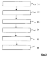
- Figure 3 shows a flow diagram for a possible implementation of the clipping method according to the present invention.
- a preferred implementation of the clipping method according to the invention comprises successive steps 31 to 36.
- Step 31 consists in determining the baseband signal envelope.
- Step 32 consists in detecting the position and the amplitude of signal envelope overshots having an amplitude above a predefined threshold value.
- Step 33 consists in selecting a predefined number of overshot per time window.
- Step 34 consists in generating a pulse train in phase with the baseband signal by considering only the position, the phase and the amplitude of the overshots.
- Step 35 consists in filtering the pulse train with a low pass filter.
- the central coefficient of the central filter is equal to one so that the amplitude of the filtered pulse train at a location corresponding to an overshot is equal to the difference between the amplitude of the signal overshot and the predefined threshold value.
- Step 36 consists in subtracting the filtered pulse train from the signal.
- the signal should be delayed by a delay equal to the processing time required to generate the filtered pulse train in order to keep the signal and the filtered pulse train synchronized.
- the step 31 to 36 are repeated a predefined number of times.
- Figure 4 shows an example applying the clipping method according to the present invention to a signal.
- x-coordinate of the diagram represents the time and more precisely the sample number of the signal in the time window
- y-coordinate of the diagram represents the amplitude of the signal envelope
- Input signal envelope ISE, threshold value THR, pulse train PT, filtered pulse train envelope FPTE as well as clipped signal envelope CSE are represented on the diagram.
- Input signal envelope overshots OV1, ..., OV7 corresponds to peaks of input signal envelope ISE having an amplitude higher than threshold value TRH.
- Pulse train PT is deduced from input signal envelope ISE in that a pulse is associated to the maximum point of an overshot. All other values of the pulse train are set to zero.
- the amplitude of a pulse in the pulse train is equal to the difference between the overshot amplitude and the threshold value.
- the pulse is a Dirac pulse.
- Filtered pulse train envelope FPTE is obtained by filtering pulse train PT by a low pass filtered having a central coefficient of one .
- Clipped signal envelope CSE is obtained by subtracting filtered pulse train envelope FPTE from input signal envelope ISE.
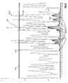
- Figure 5 shows the power spectrum of a multi-carrier signal composed of adjacent carriers clipped according to the present invention.
- the signal spectrum, SpectSig represents the range of frequencies composing the signal (x-coordinate) and the amplitude of this frequencies (y-coordinate).
- the spectrum mask, SpectMask represents the requirements, usually set by telecommunications standardization bodies, the signal spectrum should fulfill to be standard compliant.
- the signal amplitude in the frequency range extending out of the allowed frequency band is lower than the spectrum mask requirements and as a consequence standard compliant. This has the advantage of minimizing adjacent channel interference and as a consequence increasing the capacity of the radio communication system.
Landscapes
- Physics & Mathematics (AREA)
- Nonlinear Science (AREA)
- Engineering & Computer Science (AREA)
- Power Engineering (AREA)
- Transmitters (AREA)
- Tone Control, Compression And Expansion, Limiting Amplitude (AREA)
Abstract
Description
- Figure 1 shows an embodiment of a clipping module according to the present invention;
- Figure 2 shows an embodiment of a transmitter according to the present invention;
- Figure 3 shows a flow diagram for a possible implementation of the clipping method according to the present invention;
- Figure 4 shows an example of the clipping method according to the present invention applied on a signal;
- Figure 5 shows the power spectrum of a multi-carrier signal composed of adjacent carriers clipped according to the present invention.
Claims (10)
- Method for clipping a wideband signal (ISE) in order to eliminate signal overshots (OV1, ..., OV7) having an amplitude above a predefined threshold (THR) before submitting said wideband signal to a power amplifier, said method being characterized in subtracting from said wideband signal filtered pulses (FPTE) in phase with said wideband signal (ISE), each of said filtered pulses corresponding to one of said overshots, the amplitude of each of said filtered pulses being dependant on the amplitude of said corresponding overshot and on said predefined threshold (THR).
- Method according to claim 1, characterized in that it comprises the steps of:selecting a predefined number of signal overshots in a time window having a predefined duration;generating a digital pulse train in phase with said signal, the amplitude of each pulse being equal to the difference between said overshot amplitude and said predefined amplitude threshold if said signal amplitude is higher than said predefined threshold;filtering said pulse train by a low pass filter; andsubtracting said filtered pulse train from said wideband signal.
- Method according to claim 2, characterized in that it further comprises a step of oversampling said wideband signal at a predefined oversampling rate, said pulse train being generated at said oversampling rate.
- Method according to any of the claims 1 to 3, characterized in that it further comprising the step of in repeating at least two successive iterations of said method on said wideband signal.
- Method according to claim 4, characterized in that it further comprises a step of hard clipping after said iterations of said method.
- Method according to claim 1 characterized in that said wideband signal is a CDMA signal.
- Method according to claim 1, characterized in that said wideband signal is a multi-carrier signal constituted by a superposition of several CDMA signals on adjacent carriers.
- Transmitter to transmit a wideband signal on a radio interface, said transmitter comprising a signal synthesis module, a clipping module to eliminate signal overshots above a predefined threshold, and a power amplifier, said transmitter being characterized in that said clipping module comprises:a pulses generator for generating filtered pulses in phase with said wideband signal, each of said filtered pulses corresponding to one of said overshot, the amplitude of each of said filtered pulses being dependant on the amplitude of said corresponding overshot; anda subtractor for subtracting said filtered pulses from said wideband signal.
- Transmitter according to claim 8, characterized in that said clipping module is implemented on a DSP or a FPGA.
- Transmitter according to claim 8, characterized in that it is used in a base station of a CDMA radio communication network.
Priority Applications (4)
| Application Number | Priority Date | Filing Date | Title |
|---|---|---|---|
| EP00440273A EP1195892B1 (en) | 2000-10-06 | 2000-10-13 | Method and corresponding transmitter for predistorting a wideband radio signal to avoid clipping |
| CN01145681.7A CN1235423C (en) | 2000-10-06 | 2001-09-30 | Method for amplitude-limited wide-band radio signal and relative transmitter |
| JP2001307155A JP3954341B2 (en) | 2000-10-06 | 2001-10-03 | Method and corresponding transmitter for clipping a broadband wireless signal |
| US09/970,694 US7466966B2 (en) | 2000-10-06 | 2001-10-05 | Method for clipping a wideband radio signal and corresponding transmitter |
Applications Claiming Priority (3)
| Application Number | Priority Date | Filing Date | Title |
|---|---|---|---|
| EP00440268 | 2000-10-06 | ||
| EP00440268 | 2000-10-06 | ||
| EP00440273A EP1195892B1 (en) | 2000-10-06 | 2000-10-13 | Method and corresponding transmitter for predistorting a wideband radio signal to avoid clipping |
Publications (2)
| Publication Number | Publication Date |
|---|---|
| EP1195892A1 true EP1195892A1 (en) | 2002-04-10 |
| EP1195892B1 EP1195892B1 (en) | 2009-04-22 |
Family
ID=26073644
Family Applications (1)
| Application Number | Title | Priority Date | Filing Date |
|---|---|---|---|
| EP00440273A Expired - Lifetime EP1195892B1 (en) | 2000-10-06 | 2000-10-13 | Method and corresponding transmitter for predistorting a wideband radio signal to avoid clipping |
Country Status (4)
| Country | Link |
|---|---|
| US (1) | US7466966B2 (en) |
| EP (1) | EP1195892B1 (en) |
| JP (1) | JP3954341B2 (en) |
| CN (1) | CN1235423C (en) |
Cited By (7)
| Publication number | Priority date | Publication date | Assignee | Title |
|---|---|---|---|---|
| WO2002089315A3 (en) * | 2001-04-25 | 2003-11-06 | Filtronic Plc | Electrical signal pre-conditioning |
| EP1396970A1 (en) * | 2002-08-30 | 2004-03-10 | Alcatel | Method for scaling signal peaks and corresponding transmitter |
| EP1659703A1 (en) * | 2004-11-17 | 2006-05-24 | Alcatel | Method and means for decreasing the peak to average power ratio in mobile phones |
| WO2008043881A1 (en) * | 2006-10-12 | 2008-04-17 | Nokia Corporation | Method, clipper module, and transmitter |
| EP2109227A4 (en) * | 2007-03-06 | 2010-12-01 | Huawei Tech Co Ltd | Method, device for reducing signal peak value and transmitting device |
| US9596114B2 (en) | 2013-01-21 | 2017-03-14 | Nec Corporation | Peak suppressing device and peak suppressing method |
| US11139781B2 (en) | 2016-02-01 | 2021-10-05 | National University Of Ireland, Maynooth | Power amplifiers |
Families Citing this family (35)
| Publication number | Priority date | Publication date | Assignee | Title |
|---|---|---|---|---|
| FI20020820A0 (en) * | 2002-04-30 | 2002-04-30 | Nokia Corp | Procedure for limiting signal and transmitter |
| JP4287225B2 (en) | 2003-09-18 | 2009-07-01 | 株式会社日立国際電気 | Transmitter |
| BRPI0515126A (en) * | 2004-08-30 | 2008-07-08 | Matsushita Electric Industrial Co Ltd | crust power suppression apparatus and ridge power suppression method |
| US7355470B2 (en) | 2006-04-24 | 2008-04-08 | Parkervision, Inc. | Systems and methods of RF power transmission, modulation, and amplification, including embodiments for amplifier class transitioning |
| US7327803B2 (en) | 2004-10-22 | 2008-02-05 | Parkervision, Inc. | Systems and methods for vector power amplification |
| FI20055012A0 (en) * | 2005-01-07 | 2005-01-07 | Nokia Corp | Trimming a broadcast signal |
| CN1921468B (en) * | 2005-08-25 | 2014-02-19 | 中兴通讯股份有限公司 | Device and method for reducing apex-average ratio of crossing frequency division multiplexing communication system |
| JP4745001B2 (en) * | 2005-09-21 | 2011-08-10 | 三菱電機株式会社 | Peak suppressor and transmitter |
| WO2007043151A1 (en) | 2005-10-06 | 2007-04-19 | Matsushita Electric Industrial Co., Ltd. | Multi-carrier transmission device |
| US20130078934A1 (en) | 2011-04-08 | 2013-03-28 | Gregory Rawlins | Systems and Methods of RF Power Transmission, Modulation, and Amplification |
| US8013675B2 (en) | 2007-06-19 | 2011-09-06 | Parkervision, Inc. | Combiner-less multiple input single output (MISO) amplification with blended control |
| US7911272B2 (en) | 2007-06-19 | 2011-03-22 | Parkervision, Inc. | Systems and methods of RF power transmission, modulation, and amplification, including blended control embodiments |
| US7937106B2 (en) | 2006-04-24 | 2011-05-03 | ParkerVision, Inc, | Systems and methods of RF power transmission, modulation, and amplification, including architectural embodiments of same |
| US8031804B2 (en) | 2006-04-24 | 2011-10-04 | Parkervision, Inc. | Systems and methods of RF tower transmission, modulation, and amplification, including embodiments for compensating for waveform distortion |
| JP4750652B2 (en) * | 2006-08-30 | 2011-08-17 | 株式会社エヌ・ティ・ティ・ドコモ | Apparatus and method for transmitting signals in multi-carrier scheme |
| US7738539B2 (en) * | 2006-12-01 | 2010-06-15 | Sony Ericsson Mobile Communications Ab | Current consumption reduction with low power amplifier |
| US7995975B2 (en) * | 2006-12-21 | 2011-08-09 | Telefonaktiebolaget Lm Ericsson (Publ) | Method and apparatus for signal peak-to-average ratio reduction |
| US7620129B2 (en) | 2007-01-16 | 2009-11-17 | Parkervision, Inc. | RF power transmission, modulation, and amplification, including embodiments for generating vector modulation control signals |
| WO2008144017A1 (en) | 2007-05-18 | 2008-11-27 | Parkervision, Inc. | Systems and methods of rf power transmission, modulation, and amplification |
| WO2009005768A1 (en) | 2007-06-28 | 2009-01-08 | Parkervision, Inc. | Systems and methods of rf power transmission, modulation, and amplification |
| WO2009145887A1 (en) | 2008-05-27 | 2009-12-03 | Parkervision, Inc. | Systems and methods of rf power transmission, modulation, and amplification |
| JP5239594B2 (en) * | 2008-07-30 | 2013-07-17 | 富士通株式会社 | Clip detection apparatus and method |
| TWI359559B (en) * | 2008-08-07 | 2012-03-01 | Ind Tech Res Inst | Power amplifier system and control method and cont |
| WO2011074164A1 (en) * | 2009-12-15 | 2011-06-23 | パナソニック株式会社 | Automatic gain control device, receiver, electronic device, and automatic gain control method |
| JP5201158B2 (en) | 2010-02-24 | 2013-06-05 | 住友電気工業株式会社 | Signal processing circuit and communication apparatus having this circuit |
| JP5212402B2 (en) | 2010-02-24 | 2013-06-19 | 住友電気工業株式会社 | Peak power suppression circuit and communication device having this circuit |
| JP5808895B2 (en) * | 2010-08-31 | 2015-11-10 | 日本無線株式会社 | Amplitude limiter |
| CN102164023A (en) * | 2011-03-31 | 2011-08-24 | 复旦大学 | Method for decoding adaptive dynamic quantitative low density parity-check codes (LDPC) |
| EP2715867A4 (en) | 2011-06-02 | 2014-12-17 | Parkervision Inc | Antenna control |
| US8503950B1 (en) * | 2011-08-02 | 2013-08-06 | Xilinx, Inc. | Circuit and method for crest factor reduction |
| JP2013042232A (en) * | 2011-08-11 | 2013-02-28 | Shimada Phys & Chem Ind Co Ltd | Peak suppressor |
| WO2015042142A1 (en) | 2013-09-17 | 2015-03-26 | Parkervision, Inc. | Method, apparatus and system for rendering an information bearing function of time |
| US20150223176A1 (en) * | 2014-02-02 | 2015-08-06 | Redline Innovations Group Inc. | Systems and methods for reducing peak to average power ratio |
| US9641373B2 (en) * | 2015-06-19 | 2017-05-02 | Futurewei Technologies, Inc. | Peak-to-average power ratio (PAPR) reduction in fronthauls |
| US10594269B2 (en) * | 2018-08-08 | 2020-03-17 | Shenzhen GOODIX Technology Co., Ltd. | Crest factor reduction in power amplifier circuits |
Citations (4)
| Publication number | Priority date | Publication date | Assignee | Title |
|---|---|---|---|---|
| US3675138A (en) * | 1970-09-23 | 1972-07-04 | Communications Satellite Corp | Reduction of intermodulation products |
| US4272846A (en) * | 1978-02-01 | 1981-06-09 | Kokusai Denshin Denwa Kabushiki Kaisha | Method for cancelling impulsive noise |
| US5126687A (en) * | 1990-06-07 | 1992-06-30 | Fujitsu Limited | Amplifier system for automatically minimizing distortion |
| EP0940911A1 (en) * | 1998-03-05 | 1999-09-08 | Lucent Technologies Inc. | Method and apparatus for tailored distortion of a signal prior to amplification |
Family Cites Families (4)
| Publication number | Priority date | Publication date | Assignee | Title |
|---|---|---|---|---|
| US4890297A (en) * | 1988-10-19 | 1989-12-26 | Unisys Corp. | Burst jammer erasure circuit for spread spectrum receivers |
| US5631969A (en) * | 1993-03-25 | 1997-05-20 | Ericsson Inc. | System for limiting the magnitude of sampled data |
| US6256157B1 (en) * | 1998-05-15 | 2001-07-03 | International Business Machines Corporation | Method and apparatus for removing noise spikes |
| US6337999B1 (en) * | 1998-12-18 | 2002-01-08 | Orban, Inc. | Oversampled differential clipper |
-
2000
- 2000-10-13 EP EP00440273A patent/EP1195892B1/en not_active Expired - Lifetime
-
2001
- 2001-09-30 CN CN01145681.7A patent/CN1235423C/en not_active Expired - Lifetime
- 2001-10-03 JP JP2001307155A patent/JP3954341B2/en not_active Expired - Lifetime
- 2001-10-05 US US09/970,694 patent/US7466966B2/en not_active Expired - Lifetime
Patent Citations (4)
| Publication number | Priority date | Publication date | Assignee | Title |
|---|---|---|---|---|
| US3675138A (en) * | 1970-09-23 | 1972-07-04 | Communications Satellite Corp | Reduction of intermodulation products |
| US4272846A (en) * | 1978-02-01 | 1981-06-09 | Kokusai Denshin Denwa Kabushiki Kaisha | Method for cancelling impulsive noise |
| US5126687A (en) * | 1990-06-07 | 1992-06-30 | Fujitsu Limited | Amplifier system for automatically minimizing distortion |
| EP0940911A1 (en) * | 1998-03-05 | 1999-09-08 | Lucent Technologies Inc. | Method and apparatus for tailored distortion of a signal prior to amplification |
Cited By (11)
| Publication number | Priority date | Publication date | Assignee | Title |
|---|---|---|---|---|
| WO2002089315A3 (en) * | 2001-04-25 | 2003-11-06 | Filtronic Plc | Electrical signal pre-conditioning |
| US7330704B2 (en) | 2001-04-25 | 2008-02-12 | Filtronic Plc | Electrical signal pre-conditioning |
| EP1396970A1 (en) * | 2002-08-30 | 2004-03-10 | Alcatel | Method for scaling signal peaks and corresponding transmitter |
| US7336724B2 (en) | 2002-08-30 | 2008-02-26 | Alcatel | Method for scaling peak power amplitudes in a signal and corresponding transmitter |
| EP1659703A1 (en) * | 2004-11-17 | 2006-05-24 | Alcatel | Method and means for decreasing the peak to average power ratio in mobile phones |
| WO2008043881A1 (en) * | 2006-10-12 | 2008-04-17 | Nokia Corporation | Method, clipper module, and transmitter |
| US7920635B2 (en) | 2006-10-12 | 2011-04-05 | Nokia Corporation | Method, clipper module, and transmitter |
| EP2109227A4 (en) * | 2007-03-06 | 2010-12-01 | Huawei Tech Co Ltd | Method, device for reducing signal peak value and transmitting device |
| CN101262256B (en) * | 2007-03-06 | 2013-08-14 | 华为技术有限公司 | Method, device and sending device for reducing signal peak |
| US9596114B2 (en) | 2013-01-21 | 2017-03-14 | Nec Corporation | Peak suppressing device and peak suppressing method |
| US11139781B2 (en) | 2016-02-01 | 2021-10-05 | National University Of Ireland, Maynooth | Power amplifiers |
Also Published As
| Publication number | Publication date |
|---|---|
| EP1195892B1 (en) | 2009-04-22 |
| JP2002185432A (en) | 2002-06-28 |
| JP3954341B2 (en) | 2007-08-08 |
| US7466966B2 (en) | 2008-12-16 |
| CN1359245A (en) | 2002-07-17 |
| CN1235423C (en) | 2006-01-04 |
| US20020042253A1 (en) | 2002-04-11 |
Similar Documents
| Publication | Publication Date | Title |
|---|---|---|
| EP1195892B1 (en) | Method and corresponding transmitter for predistorting a wideband radio signal to avoid clipping | |
| JP3990974B2 (en) | Peak factor reduction device | |
| EP1282225B1 (en) | Peak limiter and multi-carrier amplification apparatus | |
| EP1471659B1 (en) | Code division multiple access base station transmitter | |
| US7873116B2 (en) | Transmitter | |
| EP1396970B1 (en) | Method for scaling signal peaks and corresponding transmitter | |
| US20110059710A1 (en) | Dynamic crest factor reduction system | |
| EP3270558B1 (en) | System and apparatus for post filtering peak power reduction in multi-carrier communications systems | |
| US6266320B1 (en) | Amplitude limitation in CDMA system | |
| EP1360760B1 (en) | Amplitude limitation | |
| KR20000052914A (en) | Method of transmission and device to carry out said method | |
| US20060029158A1 (en) | Amplitude peak cancellation | |
| JP2559385B2 (en) | Reversible energy-spreading data transmission technique | |
| JP3702829B2 (en) | Peak factor reduction device | |
| KR100685567B1 (en) | Signal Notching System to Limit Signal Peaks | |
| US20200177138A1 (en) | Crest factor reduction in power amplifier circuits | |
| CN1716933B (en) | A Method for Realizing CDMA Signal Clipping | |
| JP4288458B2 (en) | Amplitude limiting circuit and CDMA communication apparatus | |
| US7123644B2 (en) | Peak cancellation apparatus of base station transmission unit | |
| CN102025675B (en) | Method and device for reducing peak clipping noise interference | |
| EP1444814B1 (en) | Method and arrangement for limiting signal in radio transmitter | |
| US20030137949A1 (en) | Method and an electronic circuit for clipping of signals | |
| JP2005057532A (en) | Electric power limiting circuit | |
| KR20060103370A (en) | A New Adaptive Power Amplifier Using Envelope Detection and Crosstalk Cancellation and Its Control Method | |
| Cheaito et al. | Performance Analysis of a Multiplex With Different PAPR Reduction Techniques |
Legal Events
| Date | Code | Title | Description |
|---|---|---|---|
| PUAI | Public reference made under article 153(3) epc to a published international application that has entered the european phase |
Free format text: ORIGINAL CODE: 0009012 |
|
| AK | Designated contracting states |
Kind code of ref document: A1 Designated state(s): AT BE CH CY DE DK ES FI FR GB GR IE IT LI LU MC NL PT SE |
|
| AX | Request for extension of the european patent |
Free format text: AL;LT;LV;MK;RO;SI |
|
| 17P | Request for examination filed |
Effective date: 20020724 |
|
| AKX | Designation fees paid |
Free format text: AT BE CH CY DE DK ES FI FR GB GR IE IT LI LU MC NL PT SE |
|
| 17Q | First examination report despatched |
Effective date: 20061222 |
|
| RAP1 | Party data changed (applicant data changed or rights of an application transferred) |
Owner name: ALCATEL LUCENT |
|
| GRAP | Despatch of communication of intention to grant a patent |
Free format text: ORIGINAL CODE: EPIDOSNIGR1 |
|
| GRAS | Grant fee paid |
Free format text: ORIGINAL CODE: EPIDOSNIGR3 |
|
| GRAA | (expected) grant |
Free format text: ORIGINAL CODE: 0009210 |
|
| AK | Designated contracting states |
Kind code of ref document: B1 Designated state(s): AT BE CH CY DE DK ES FI FR GB GR IE IT LI LU MC NL PT SE |
|
| REG | Reference to a national code |
Ref country code: GB Ref legal event code: FG4D |
|
| REG | Reference to a national code |
Ref country code: CH Ref legal event code: EP |
|
| REG | Reference to a national code |
Ref country code: IE Ref legal event code: FG4D |
|
| REF | Corresponds to: |
Ref document number: 60042072 Country of ref document: DE Date of ref document: 20090604 Kind code of ref document: P |
|
| NLV1 | Nl: lapsed or annulled due to failure to fulfill the requirements of art. 29p and 29m of the patents act | ||
| PG25 | Lapsed in a contracting state [announced via postgrant information from national office to epo] |
Ref country code: PT Free format text: LAPSE BECAUSE OF FAILURE TO SUBMIT A TRANSLATION OF THE DESCRIPTION OR TO PAY THE FEE WITHIN THE PRESCRIBED TIME-LIMIT Effective date: 20090822 Ref country code: ES Free format text: LAPSE BECAUSE OF FAILURE TO SUBMIT A TRANSLATION OF THE DESCRIPTION OR TO PAY THE FEE WITHIN THE PRESCRIBED TIME-LIMIT Effective date: 20090802 Ref country code: AT Free format text: LAPSE BECAUSE OF FAILURE TO SUBMIT A TRANSLATION OF THE DESCRIPTION OR TO PAY THE FEE WITHIN THE PRESCRIBED TIME-LIMIT Effective date: 20090422 Ref country code: FI Free format text: LAPSE BECAUSE OF FAILURE TO SUBMIT A TRANSLATION OF THE DESCRIPTION OR TO PAY THE FEE WITHIN THE PRESCRIBED TIME-LIMIT Effective date: 20090422 |
|
| PG25 | Lapsed in a contracting state [announced via postgrant information from national office to epo] |
Ref country code: SE Free format text: LAPSE BECAUSE OF FAILURE TO SUBMIT A TRANSLATION OF THE DESCRIPTION OR TO PAY THE FEE WITHIN THE PRESCRIBED TIME-LIMIT Effective date: 20090722 Ref country code: NL Free format text: LAPSE BECAUSE OF FAILURE TO SUBMIT A TRANSLATION OF THE DESCRIPTION OR TO PAY THE FEE WITHIN THE PRESCRIBED TIME-LIMIT Effective date: 20090422 |
|
| PG25 | Lapsed in a contracting state [announced via postgrant information from national office to epo] |
Ref country code: DK Free format text: LAPSE BECAUSE OF FAILURE TO SUBMIT A TRANSLATION OF THE DESCRIPTION OR TO PAY THE FEE WITHIN THE PRESCRIBED TIME-LIMIT Effective date: 20090422 |
|
| PG25 | Lapsed in a contracting state [announced via postgrant information from national office to epo] |
Ref country code: BE Free format text: LAPSE BECAUSE OF FAILURE TO SUBMIT A TRANSLATION OF THE DESCRIPTION OR TO PAY THE FEE WITHIN THE PRESCRIBED TIME-LIMIT Effective date: 20090422 |
|
| PLBE | No opposition filed within time limit |
Free format text: ORIGINAL CODE: 0009261 |
|
| STAA | Information on the status of an ep patent application or granted ep patent |
Free format text: STATUS: NO OPPOSITION FILED WITHIN TIME LIMIT |
|
| 26N | No opposition filed |
Effective date: 20100125 |
|
| PG25 | Lapsed in a contracting state [announced via postgrant information from national office to epo] |
Ref country code: MC Free format text: LAPSE BECAUSE OF NON-PAYMENT OF DUE FEES Effective date: 20091031 |
|
| REG | Reference to a national code |
Ref country code: CH Ref legal event code: PL |
|
| PG25 | Lapsed in a contracting state [announced via postgrant information from national office to epo] |
Ref country code: GR Free format text: LAPSE BECAUSE OF FAILURE TO SUBMIT A TRANSLATION OF THE DESCRIPTION OR TO PAY THE FEE WITHIN THE PRESCRIBED TIME-LIMIT Effective date: 20090723 Ref country code: LI Free format text: LAPSE BECAUSE OF NON-PAYMENT OF DUE FEES Effective date: 20091031 Ref country code: IE Free format text: LAPSE BECAUSE OF NON-PAYMENT OF DUE FEES Effective date: 20091013 Ref country code: CH Free format text: LAPSE BECAUSE OF NON-PAYMENT OF DUE FEES Effective date: 20091031 |
|
| PG25 | Lapsed in a contracting state [announced via postgrant information from national office to epo] |
Ref country code: LU Free format text: LAPSE BECAUSE OF NON-PAYMENT OF DUE FEES Effective date: 20091013 |
|
| PG25 | Lapsed in a contracting state [announced via postgrant information from national office to epo] |
Ref country code: CY Free format text: LAPSE BECAUSE OF FAILURE TO SUBMIT A TRANSLATION OF THE DESCRIPTION OR TO PAY THE FEE WITHIN THE PRESCRIBED TIME-LIMIT Effective date: 20090422 |
|
| REG | Reference to a national code |
Ref country code: GB Ref legal event code: 732E Free format text: REGISTERED BETWEEN 20130926 AND 20131002 |
|
| REG | Reference to a national code |
Ref country code: FR Ref legal event code: GC Effective date: 20131018 |
|
| REG | Reference to a national code |
Ref country code: FR Ref legal event code: RG Effective date: 20141016 |
|
| REG | Reference to a national code |
Ref country code: FR Ref legal event code: CA Effective date: 20150521 |
|
| REG | Reference to a national code |
Ref country code: FR Ref legal event code: CA Effective date: 20150521 |
|
| REG | Reference to a national code |
Ref country code: FR Ref legal event code: PLFP Year of fee payment: 16 |
|
| REG | Reference to a national code |
Ref country code: FR Ref legal event code: PLFP Year of fee payment: 17 |
|
| REG | Reference to a national code |
Ref country code: FR Ref legal event code: PLFP Year of fee payment: 18 |
|
| REG | Reference to a national code |
Ref country code: FR Ref legal event code: PLFP Year of fee payment: 19 |
|
| PGFP | Annual fee paid to national office [announced via postgrant information from national office to epo] |
Ref country code: FR Payment date: 20190913 Year of fee payment: 20 |
|
| PGFP | Annual fee paid to national office [announced via postgrant information from national office to epo] |
Ref country code: DE Payment date: 20191001 Year of fee payment: 20 |
|
| PGFP | Annual fee paid to national office [announced via postgrant information from national office to epo] |
Ref country code: IT Payment date: 20191009 Year of fee payment: 20 |
|
| PGFP | Annual fee paid to national office [announced via postgrant information from national office to epo] |
Ref country code: GB Payment date: 20191010 Year of fee payment: 20 |
|
| REG | Reference to a national code |
Ref country code: DE Ref legal event code: R071 Ref document number: 60042072 Country of ref document: DE |
|
| REG | Reference to a national code |
Ref country code: GB Ref legal event code: PE20 Expiry date: 20201012 |
|
| PG25 | Lapsed in a contracting state [announced via postgrant information from national office to epo] |
Ref country code: GB Free format text: LAPSE BECAUSE OF EXPIRATION OF PROTECTION Effective date: 20201012 |