EP1195749A2 - Multi-layer rotary recording medium and recording/reproducing method and apparatus thereof - Google Patents
Multi-layer rotary recording medium and recording/reproducing method and apparatus thereof Download PDFInfo
- Publication number
- EP1195749A2 EP1195749A2 EP01123274A EP01123274A EP1195749A2 EP 1195749 A2 EP1195749 A2 EP 1195749A2 EP 01123274 A EP01123274 A EP 01123274A EP 01123274 A EP01123274 A EP 01123274A EP 1195749 A2 EP1195749 A2 EP 1195749A2
- Authority
- EP
- European Patent Office
- Prior art keywords
- recording
- correcting
- layer
- reproduction
- read signal
- Prior art date
- Legal status (The legal status is an assumption and is not a legal conclusion. Google has not performed a legal analysis and makes no representation as to the accuracy of the status listed.)
- Withdrawn
Links
Images







Classifications
-
- G—PHYSICS
- G11—INFORMATION STORAGE
- G11B—INFORMATION STORAGE BASED ON RELATIVE MOVEMENT BETWEEN RECORD CARRIER AND TRANSDUCER
- G11B7/00—Recording or reproducing by optical means, e.g. recording using a thermal beam of optical radiation by modifying optical properties or the physical structure, reproducing using an optical beam at lower power by sensing optical properties; Record carriers therefor
- G11B7/12—Heads, e.g. forming of the optical beam spot or modulation of the optical beam
- G11B7/125—Optical beam sources therefor, e.g. laser control circuitry specially adapted for optical storage devices; Modulators, e.g. means for controlling the size or intensity of optical spots or optical traces
- G11B7/126—Circuits, methods or arrangements for laser control or stabilisation
-
- G—PHYSICS
- G11—INFORMATION STORAGE
- G11B—INFORMATION STORAGE BASED ON RELATIVE MOVEMENT BETWEEN RECORD CARRIER AND TRANSDUCER
- G11B7/00—Recording or reproducing by optical means, e.g. recording using a thermal beam of optical radiation by modifying optical properties or the physical structure, reproducing using an optical beam at lower power by sensing optical properties; Record carriers therefor
- G11B7/004—Recording, reproducing or erasing methods; Read, write or erase circuits therefor
- G11B7/0045—Recording
-
- G—PHYSICS
- G11—INFORMATION STORAGE
- G11B—INFORMATION STORAGE BASED ON RELATIVE MOVEMENT BETWEEN RECORD CARRIER AND TRANSDUCER
- G11B7/00—Recording or reproducing by optical means, e.g. recording using a thermal beam of optical radiation by modifying optical properties or the physical structure, reproducing using an optical beam at lower power by sensing optical properties; Record carriers therefor
- G11B7/004—Recording, reproducing or erasing methods; Read, write or erase circuits therefor
- G11B7/005—Reproducing
-
- G—PHYSICS
- G11—INFORMATION STORAGE
- G11B—INFORMATION STORAGE BASED ON RELATIVE MOVEMENT BETWEEN RECORD CARRIER AND TRANSDUCER
- G11B7/00—Recording or reproducing by optical means, e.g. recording using a thermal beam of optical radiation by modifying optical properties or the physical structure, reproducing using an optical beam at lower power by sensing optical properties; Record carriers therefor
- G11B7/007—Arrangement of the information on the record carrier, e.g. form of tracks, actual track shape, e.g. wobbled, or cross-section, e.g. v-shaped; Sequential information structures, e.g. sectoring or header formats within a track
- G11B7/00745—Sectoring or header formats within a track
Definitions
- the present invention relates to a method and apparatus for recording and/or reproducing an optical recording medium and, more particularly to a method and apparatus for recording and/or reproducing a multi-layer rotary recording medium having a plurality of recording layers having data recording regions divided by preformatted regions,
- multi-layer optical disc capable of increasing the recording capacity per surface is developed as a large-capacity recording medium.
- the multi-layer optical disc has a structure having a plurality of laminated or stacked recording layers spaced at a comparatively small predetermined interval.
- a multi-layer optical disc capable of recording has been developed using a recording medium, for example, a phase-change medium.
- the two-layer DVD disc has a structure having phase-change recording films formed in an upper or first recording layer (i.e. layer closer to an optical-pickup objective lens) and a lower or second recording layer.
- first recording layer i.e. layer closer to an optical-pickup objective lens
- second recording layer i.e. layer closer to an optical-pickup objective lens
- laser light is focused to any of the recording layers to record or reproduce a signal to or from the recording layer.
- the two-layer DVD disc or the like consideration is given to the case where an irradiation light beam is focused on the second recording layer (hereinafter, referred simply to as second layer) to carry out recording and/or reproduction (hereinafter, referred to as recording/reproduction). More particularly, consideration is given to a case where a light beam is irradiated on the second layer while being passed through the first recording layer (hereinafter, referred simply to as first layer) to carry out recording/reproduction of a data signal.
- the affections of the first layer is an amount of change of the reflection light reflected from the first layer to reach a light-receiving system and an amount of change of the transmission light through the first layer to the second layer.
- the affection can be reduced by devising the structure of a detecting system or the like.
- the amount of change in the transmission light through the first layer appears as a fluctuation in recording light intensity during recording and as fluctuation in reproduced-signal level during reproduction, which in some cases cannot be ignored.
- phase-change medium for example, of germanium antimony tellurium (GeSbTe) in the recording layer
- transmittance is different between a crystalline region and an amorphous region, i.e., the transmittance through the crystalline region is lower than the transmittance through the amorphous region.
- the phase-change medium has a crystalline region of almost 100% in an unrecorded region, while a crystalline region and an amorphous region exist in a mixed manner in a recorded region. Also, the recorded region in the first layer is out of focus and hence a record signal per se is not reproduced there.
- the transmittance of a light beam is an averaged transmittance of those through the crystalline region and the amorphous region. Consequently, during reproducing from the second layer, the amount of reception-light (i.e. RF signal level during reproduction) varies according to whether the first layer is recorded or unrecorded.
- the multi-layer optical recording disc is generally provided with preformatted regions where no data signals are recorded.
- a DVD-RAM Random Access Memory
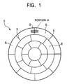
- the recording region is divided by preformatted areas 5 in a tracing direction of a light beam (i.e. in the tangential or circumferential direction) to form a plurality of data areas 6 in a concentric form.
- one preformatted area 5 and the adjacent one data area 6 constitute a sector 7.
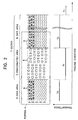
- Fig. 2 shows a typical magnification view of a region of a preformatted area 5 and its vicinity (portion A), together with the transmittance in the areas thereof.
- Information data such as an address, is recorded in the preformatted area 5 in the form of emboss pits 8.
- the data area 6 comprises lands (L) and grooves (G). Record marks 9 are formed in the region where data is recorded.
- the average transmittance of a data area 6 where data is recorded (T D ) is greater than the transmittance of the preformatted area 5 (T P ).
- the transmittance of the first-layer reformatted area 5 varies, hence varying the recording light intensity or reproduced signal intensity in the second layer during recording or reproduction.
- no recording is made to the preformatted area. Accordingly, in order to avoid an adverse effect during recording or reproduction of the multi-layer optical recording medium having preformatted area, there is a need to completely match the positions of the preformatted areas between the first layer and the second layer.
- the preformatted areas between the layers if overlapped even in part, make it difficult to detect a correct position and make a correction signal complicated. Consequently, there is a necessity to distinctly deviate the preformatted areas between the layers, on the premise of making the correction.
- a recordable multi-layer optical recording medium laminated with a plurality of recording layers each having data recording areas divided in a tracing direction of a light beam by preformatted areas, wherein the preformatted areas are formed without any overlap with one another in a laminated direction between the recording layers.
- a recording method of a recordable multi-layer rotary recording medium having a plurality of recording layers each having data recording areas divided in a tracing direction of a light beam by preformatted areas which comprises the steps of a reading step of detecting a reflection light from a recording layer to which a recording is to be made and converting the detected light into a read signal; a detecting step of detecting a position of a preformatted area of a recording layer which the optical beam transmits therethrough other than the recording layer to which a recording is to be made; and a correcting step of correcting intensity of an irradiation light beam upon recording based on the read signal and the preformatted area position.
- a reproducing method of a recordable multi-layer rqtary recording medium having a plurality of recording layers each having data recording areas divided in a tracing direction of a light beam by preformatted areas which comprises the steps of a reading step of detecting a reflection light from a recording layer from which a reproduction is to be made and converting the detected light into a read signal; a detecting step of detecting a position of a preformatted area of a recording layer which the optical beam transmits therethrough other than the recording layer from which a reproduction is to be made; and a correcting step of correcting a reproduced signal upon reproduction on the basis of the read signal and the preformatted area position.
- a recording apparatus of a recordable multi-layer rotary recording medium having a plurality of recording layers each having data recording areas divided in a tracing direction of a light beam by preformatted areas, which comprises a reading portion for detecting a reflection light from a recording layer to which a recording is to be made and converting the detected light into a read signal; a detecting portion for detecting a position of a preformatted area of a recording layer which the optical beam transmits therethrough other than the recording layer to which a recording is to be made; and a correcting portion for correcting intensity of an irradiation light beam upon recording based on the read signal and the preformatted area position.
- a reproducing apparatus of a recordable multi-layer rotary recording medium having a plurality of recording layers each having data recording areas divided in a tracing direction of a light beam by preformatted areas which comprises a reading portion for detecting a reflection light from a recording layer from which a reproduction is to be made and converting the detected light into a read signal; a detecting portion for detecting a position of a preformatted area of a recording layer which the optical beam transmits therethrough other than the recording layer from which a reproduction is to be made; and a correcting portion for correcting a reproduced signal upon reproduction on the basis of the read signal and the preformatted area position.
- first recording layer (upper layer) 11 and a second recording layer (lower layer) 12 are formed in the optical disc in the order with respect to an irradiation direction of a laser beam for recording or reproducing information data signals.
- the second layer 12 is a recording layer distant from an objective lens for focusing a laser beam.
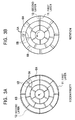
- Figs. 3A and 3B are plan views for illustrating a positional deviation between the preformatted areas 5A and 5B respectively in the first recording layer 11 and the second recording layer 12 (hereinafter, referred to as first layer and second layer).
- the first layer 11 is shown with the solid lines and the second layer 12 with the broken lines.
- the cause of positional deviation occurrence between the preformatted areas 5A and 5B is to be classified as those due to the deviation of the centers of the first layer 11 and the second layers, i.e. eccentricity (Fig. 3A) and those due to the deviation in rotational direction (Fig. 3B).
- Fig. 4 is a plan view illustrating a two-layer optical rotary recording medium 10 of a first embodiment of the present invention. Similarly to Fig. 3, representation is only made by the lines showing the division of the recording layers, for simplicity of description. Note that only deviation in rotational direction is shown in Fig. 4.
- the first layer 11 and the second layer 12 have recording areas divided in a concentric (annular) form.
- Fig. 4 shows the case in which the recording areas in the outer periphery of the fist layer 11 and the second layer 12 are each divided into eight data areas 6A, 6B by preformatted areas 5A, 5B. Similarly, the recording areas in the intermediate and inner peripheral regions are, respectively, divided into seven and six data areas 6A, 6B.
- the first layer 11 and the second layer 12 have a deviation of eccentricity and/or rotation which is intentionally provided in the manufacturing process, whereby the preformatted areas 5A and 5B are formed in distinctively deviated positions.
- Fig. 5 is a sectional view in a beam tracing direction, showing a relationship between the preformatted areas 5A and 5B and the data areas 6A, 6B of the two-layer optical rotary recording medium 10.
- the preformatted areas 5A and 5B are formed deviated throughout the plane of the recording medium 10 in such a manner that the preformatted areas 5A and 5B does not have overlap portions in a direction of recording-layer lamination.
- the above-described recording-area divisional form and division number is a mere exemplification, i.e., it is satisfactory to make division so as to avoid overlaps of preformatted areas.
- Fig. 4 exemplified for a deviation in a rotation direction
- the present invention can applied to a case wherein deviation due to eccentricity exists.
- the preformatted areas should be formed without overlap in the direction of lamination between the recording layers.
- FIG. 6 is a block diagram showing a configuration of a recording/reproducing apparatus (hereinafter, referred simply to as recording/reproducing apparatus) of a second embodiment of the present invention.
- An optical pickup 21 includes an optical system including a focus lens, a beam splitter and an objective lens, a light-source laser diode and a photodetector (not shown).
- the optical pickup 21 emits a light beam, as recording or reproducing light, on an optical disc 10 which is a recording medium.
- the optical pickup 21 detects a reflection light from a recording layer of the optical disc, thereby reading out a signal corresponding to a track and information pit or recording mark formed on the optical disc 10. Tracking servo and focus servo control on the objective lens is performed in order to correctly focus the light beam on an information recording surface of the optical disc 10 (not shown).
- the read signal (RF signal) supplied from the optical pickup 21 is amplified in an amplifier circuit 22 and supplied to a prepit reading circuit 23.
- the prepit reading circuit 23 extracts prepit and wobble signals.
- a synchronizing clock and timing signal generating circuit 24 generates a clock signal (CK) and a timing signal synchronized with rotation of the optical disc 10.
- the generated signals are supplied to a control section (CPU) 26 for controlling the apparatus overall.
- the generated signals are used for various control purposes.
- the CPU 26 detects from the signals a preformatting position of a recording layer to which a recording is to be made.
- the CPU 26 may be provided with or connected to a storage device (not shown) for storing data as necessary.
- the read signal amplified in the amplifier circuit 22 is also supplied to a low-pass filter (LPF) 28 and only a low-frequency component of the signal is supplied to an analog-digital (A/D) converter 29.
- LPF low-pass filter
- A/D analog-digital converter 29.
- the signal converted into a digital signal in the A/D converter 29 is supplied to a memory 31 in accordance with a timing signal from the timing signal generating circuit 24 and stored therein.
- the signal stored in the memory 31 is supplied to a recordation-correcting signal generating circuit 33.
- the signal is binarized in a binarizing circuit 34 provided in the recordation-correcting signal generating circuit 33, and then multiplied by a coefficient ( ⁇ ) in a multiplier 35A and added with an offset ( ⁇ ) in an adder 35B, thereby a recordation correcting signal is generated.
- the recordation correcting signal is sent from the recordation-correcting signal generating circuit 33 to a laser power control circuit 36. In the laser power control circuit 36, a laser beam power upon recording is controlled on the basis of the recordation-correcting signal.
- the signal stored in the memory 31 is also supplied to a reproduction-correction signal generating circuit 37.
- This signal is binarized in a binarizing circuit 38 provided in the reproduction-correction signal generating circuit 37. and then multiplied by a coefficient ( ⁇ ) and added with an offset ( ⁇ ) in a multiplier 39A and an adder 39B, thereby a reproduction-gain correction signal is generated which represents an amount of gain-correction (hereinafter, simply referred to as gain-correction amount) upon reproduction.
- the binary signal from the binarizing circuit 38 is multiplied by a coefficient ( ⁇ ) in a multiplier 39C, thereby a reproduction-offset correction signal is generated which represents an offset correction amount during reproduction.
- the multipliers 41A and adder 41B the read signal from the amplifier circuit 22 is corrected using the reproduction-gain correction signal and the reproduction-offset correction signal and then supplied to a signal reproducing system 43.
- the recordation-correcting signal generating circuit 33 and the reproduction-correction signal generating circuit 37 are connected to a control bus of the CPU 26, and controlled by the CPU 26.
- the control signal CS supplied through the control bus contains the foregoing coefficients and offset values ( ⁇ , ⁇ ) and ( ⁇ , ⁇ , ⁇ ).
- the recordation-correcting signal generating circuit 33 and the reproduction-correction signal generating circuit 37 are shown by separate circuit blocks, a digital signal processor (DSP) or the like may be used. Also, the binarizing circuits 34, 38, although not necessarily required, are effective in reducing the scale of the processing circuit.
- DSP digital signal processor
- the signal reproducing system 43 is a general signal reproducing circuit formed by an LPF 44, a high-pass filter (HPF) and ATC circuit 45, a PLL circuit 46 and a signal reading circuit 47, to output a corrected read signal as a reproduced signal.
- the signal reproducing system 43 is controlled by the CPU 26 through a control bus.
- Such adaptive processing can be made by implementing such control using the signal from the reproduction-correction signal generating circuit 37.
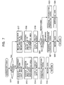
- step S11 It is determined whether or not the disc set on the recording/reproducing apparatus is already recorded (step S11). When it is determined that the disc is not already recorded, the reflection-light amount change in an unrecorded state is measured as a reproduced RF signal (step S12).
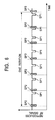
- Fig. 8 shows a reproduced RF signal read from a layer (second layer 12) to which a recording is to be made, in respect of one rotation of the optical disc.
- the preformat-signals (SP2) of the second layer 12 appear with a period of the preformatted areas in the reproduced signal.
- the preformat-signals (SP1) of the first layer 11 appear in accordance with the eccentricity amount and the deviation in rotational direction
- a signal representing a reflection light amount is obtained by the LPF 28 from the reproduced RF signal.
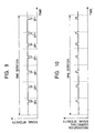
- an amount of variation due to the first-layer preformatted area is extracted as shown in Fig. 9 (step S13).
- the extracted data is stored in the memory 31 (step S14).
- the extracted data stored in the memory 31 is multiplied by a coefficient ( ⁇ ) and added with an offset ( ⁇ ) so as to cancel the variation amount due to the first-layer preformatted area, thereby generating a recordation-correcting signal shown in Fig. 10 (step S15).
- the recordation-correcting signal is sent to the laser-power control circuit 36, whereby recording is performed while correcting the recording laser power in accordance with the recordation-correcting signal (step S16).
- step S17 the amount of reflection light from a recording track is measured. Note that, in step S17, measurement may be made on an amount of reflection light from an unrecorded track. Then, similarly to the foregoing, an amount of variation due to the first-layer preformatted area is extracted from the reflection-light-amount measurement data (step S18) and stored in the memory 31 (step S19). Thereafter, it is determined whether the next operation is recording operation or reproducing operation (step S20). In the case of recording operation, a recordation-correcting signal is generated (step S21) whereby recordation is carried out while correcting laser power on the basis of the recordation-correcting signal (step S22).
- the extracted data stored in the memory 31 is processed so as to cancel the variation amount given by the first-layer preformatted area.
- the extracted data is multiplied by a coefficient ( ⁇ ) and added with an offset ( ⁇ ) thereby generating a reproduction-gain correcting signal.
- the extracted data is multiplied by a coefficient ( ⁇ ) thereby generating a reproduction-offset correcting signal (step S23).
- the read signal is corrected and reproduced by the reproduction-gain correcting signal and the reproduction-offset correcting signal (step S24).
- the read signal can be corrected continuously while performing data recording or reproducing operation by repeating the recordation/reproduction correcting procedure of the flowchart shown in Fig.7 as a loop.
- the reflection light amount varies on each measurement because the amount of reflection light from the optical disc varies according to various factors as shown in Fig. 12.
- the component of variation in time can be eliminated by averaging the measurement data that are synchronized with disc rotation. For example, this can be realized by making the memory 31 in a loop structure to multiply and add measurement data into the memory 31. Or otherwise, such operation processing can be realized by the control of the CPU 26.
- the amount of variation due to the first-layer preformatted area can be extracted on the basis of a position of a preformatted area of the first layer, i.e. the recording layer through which an irradiation beam transmits.
- the preformatted area size (physical size) is previously determined. Accordingly, if a linear velocity upon reading is determined, when and what extent variation occurs can be determined by a calculation from a size (position) thereof, a distance between the recording layers and a reading optical-system setting. Consequently, by eliminating a variation smaller or greater than a predetermined value thus calculated as a variation caused by another factor, it is possible to extract only a variation due to a first-layer preformat-signal.
- This calculation processing can be realized by discrete circuit blocks, a DSP (not shown), hardware such as the CPU 26 or software installed in the CPU 26.
- the process of eliminating a variation smaller than a predetermined value can be carried out. by removing a low-frequency component from a measured signal by an LPF. for example, for extracting only a variation due to the foregoing first-layer preformat-signal,. Also, there is a merit that the amount of data stored can be reduced by using a measurement data signal and correction signal of a required frequency-band. Furthermore, the predetermined frequency-band measurement data signals thus obtained may be sampled and stored in the memory 31. This processing can be realized by providing a sampling circuit, a DSP, hardware such as the CPU 26 or software.
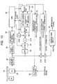
- Fig. 13 is a block diagram showing a configuration of a recording/reproducing apparatus of a third embodiment of the present invention.
- the recording/reproducing apparatus of the embodiment is particularly suited for a multi-layer recording medium having a land/groove structure comprising lands and grooves.
- a memory 31 has two channels of storage areas for lands and grooves. Also, selectors 52, 53, for selecting respective ones of data on a land and a groove, are each configured in an input/output port of the memory 31. The selectors 52, 53 operate dependent upon a control signal from a CPU 26 or a timing signal from a timing generating circuit 24. Furthermore, configured are coefficient units 51A, 51B to perform multiplying and adding operations on the data from an A/D converter 29. Consequently, the memory 31, the selectors 52, 53 and the coefficient units 51A, 51B configure a loop whereby the measurement data synchronous with disc rotation is processed with adding and averaging respectively for a land and a groove.
- the signal which represents a variation amount due to the first-layer preformatted area (first-layer preformat-signal component) thus processed and extracted is sent to a recordation-correcting signal generating circuit 33 and a reproduction-correction signal generating circuit 37.
- a recordation-correcting signal and a reproduction-correcting signal are generated on the basis of the extracted data, e.g. by a similar method to that of the first embodiment.
- the processing systems may be integrated to average the respective variations on the land and the groove.
- the selector 53 may be replaced with an averaging circuit to average the extracted data for the land and the groove.
- the recordation-correcting signal generating circuit 33 and the reproduction-correction signal generating circuit 37 may be configured to generate a correcting signal on the basis of the averaged extracted data.
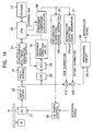
- Fig. 14 is a block diagram showing a configuration of a recording/reproducing apparatus of a fourth embodiment of the present invention.
- a timing signal from the timing generating circuit 24 can be used as the reference time.
- the reference time can be due to a starting time or ending time of a preformat-signal (SP2) in the second layer being currently read.
- the CPU 26 refers to the recording-layer characteristic data (transmittances of an amorphous and crystalline portions) stored in the storage device 57, a position of the first-layer preformatted area or a distance between the layers to calculate a variation amount due to a first-layer preformat-signal (i.e., preformat-signal component of the first-layer) on the basis of an occurrence time of the first-layer preformat-signal supplied from a preformat-signal detecting circuit 55.
- the calculation result is stored in a memory 56.
- the signal representing the calculated variation due to a first-layer preformatted area is sent to the recordation-correcting signal generating circuit 33 and the reproduction-correction signal generating circuit 37.
- a recordation-correcting signal and a reproduction-correcting signal is generated on the basis of the calculated data, for example, by a method similar to that of the foregoing embodiment.
- the required storage capacity can be greatly reduced since there is no need to store the data, as it is, which represents a variation due to a first-layer preformat-signal.
- the magnitude thereof (SP1) may be stored.
- the configuration of a recording/reproducing apparatus of a fifth embodiment of the present invention is similar to that of the fourth embodiment.
- the occurrence time of a first-layer preformat-signal is calculated from an eccentricity amount and rotational-direction deviation between the recording layers, to carry out correction. The detail of the embodiment will be described below.
- a preformat-signal (SP2) in a layer (second layer) being currently read can be used as a reference time, for example.
- the CPU 26 calculates the eccentricity ( ⁇ x, ⁇ y) and the deviation ( ⁇ ) in a rotational direction between the first layer 11 and the second layer 12 by using a first-layer preformat-signal occurrence time Ti, and stores the calculated data in the storage device 57. This processing is not required to perform on a track-by-track basis provided that the number of preformatted areas is constant within a zone.
- the CPU 26 calculates an occurrence time Ti of a first-layer preformat-signal from the radius on a track-by-track basis by the use of the stored data ( ⁇ x, ⁇ y, ⁇ ).
- Fig. 17 is a block diagram showing a configuration of a recording/reproducing apparatus of a sixth embodiment of the present invention.
- the recording/reproducing apparatus of this embodiment has a configuration to evaluate a read signal from the amplifier circuit 22 and change a correcting-signal generation process in accordance with the evaluation result.
- an evaluation circuit 63 evaluates a reproduced RF signal from the amplifier circuit 22 by using a variation parameter.
- the variation parameter is, for example, a reflection light amount, a jitter value of the reproduced RF signal, a maximum value of an envelope (Itop), an amplitude and so on.
- the evaluation circuit 63 has an evaluation function or evaluation table for evaluation.
- the evaluation result is supplied to the recordation-correcting signal generating circuit 33 and the reproduction-correction signal generating circuit 37.
- the recordation-correcting signal generating circuit 33 and reproduction-correction signal generating circuit 37 is configured such that the parameter in a generation processing function or processing function for correcting-signal generation can be changed on the basis of a signal representing the evaluation result.
- the recordation-correcting signal generating circuit 33 and the reproduction-correction signal generating circuit 37 have a plurality of processing functions or parameter tables. Or otherwise, they may be configured to change the generation process by the control of CPU 26.
- an update switch 65 is provided to update the measurement data representative of a variation amount due to a first-layer preformat-signal to be sent to the memory 31.
- the update switch 65 is controlled by the CPU 26 to operate switching the data transfer to the memory 31 when changing the disc, changing the zone in a zone constant angular velocity (ZCAV) disc or changing the foregoing processing function.
- ZCAV zone constant angular velocity
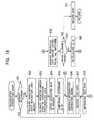
- the correcting operation of the recording/reproducing apparatus during recording is described below, with reference to the flowchart shown in Fig. 18. Note that the recordation/reproduction correcting operation is implemented under control of the control section (CPU) 26. Also, in the below, description is made, as an example for changing a recordation processing function and reproduction processing function, on the case to change the coefficients and offsets ( ⁇ , ⁇ ), ( ⁇ , ⁇ , ⁇ ) in the recordation-correcting signal generating circuit 33 and reproduction-correction signal generating circuit 37, as in the case shown in the second embodiment (see Fig. 11).
- step S31 It is determined whether the disc set on the recording/reproducing apparatus is already recorded or not (step S31). When it is determined that the disc is already recorded, the process moves to step S38. When it is determined that the disc is not recorded in step S31, measured is a change of a reflection light amount in an unrecorded state (step S32). From the measurement data of the reflection light amount, extracted is a variation amount due to the first-layer preformatted area (i.e., preformat-signal component of the first-layer) (step S33). The extracted data is stored in the memory 31 (step S34). The update switch 65 is opened to store the measurement data representing a variation amount due to a first-layer preformat-signal in the memory 31.
- a processing function in the recordation-correcting signal generating circuit 33 is temporarily defined.
- the temporary processing function uses a predetermined processing function given as initial setting. Otherwise, this may be defined on the basis of an extracted fist-layer preformat-signal component.
- the coefficient and offset ( ⁇ , ⁇ ) in the recordation-correcting signal generating circuit 33 is temporarily defined (step S35).
- a recordation-correcting signal is generated by using the temporary value (step S36), and predetermined test data is recorded on the basis of the recordation correcting signal (step S37). Then, the recorded test data is reproduced (step S38).
- the evaluation circuit 63 a reflection light amount or a reproduced RF signal jitter value, Itop, amplitude, etc. is measured from the reproduced signal (step S39).
- the evaluation circuit 63 carries out evaluation with using an evaluation function or evaluation table, to determine whether an evaluation value is within an allowable range or not (step S40). When it is determined that the evaluation value is within the allowable range, a signal representing the determination result is sent to the CPU 26 thereby executing the recording of information data to be recorded (step S41) and exiting the present routine.
- a signal representing the determination result is sent to the CPU 26 thereby executing re-calculation of a coefficient and offset ( ⁇ , ⁇ ) (step S42).
- the result of re-calculation is sent to the recordation-correcting signal generating circuit 33, thus repeating step S36 and the following.
- the correcting operation of the recording/reproducing apparatus during reproduction is described below with reference to the flowchart shown in Fig. 19.
- the reproduction correcting operation is implemented under control of the control section (CPU) 26. Also, it is carried out continuously with the recordation correcting operation, simultaneously by a double-loop configuration or independently of the recordation correcting operation.
- a change in a reflection light amount of a disc recording area is measured (step S51).
- a variation amount due to a first-layer preformatted area i.e., preformat-signal component of the first-layer
- the extracted data is stored in the memory 31 (step S53).
- a processing function in the reproduction-correction signal generating circuit 37 is temporarily defined.
- the temporary processing function uses a predetermined processing function given as an initial setting. Otherwise, it may be defined on the basis of an extracted first-layer preformat-signal component.
- a coefficient and offset ( ⁇ , ⁇ , ⁇ ) for the reproduction-correction signal generating circuit 37 is temporarily defined (step S54).
- a reproduction-correcting signal is generated using the temporary value (step S55), and predetermined test data is reproduced on the basis of the reproduction-correcting signal (step S56).
- the evaluation circuit 63 a reflection light amount or a reproduced RF signal jitter value, Itop, amplitude, etc. is measured from the reproduced signal (step S57).
- the evaluation circuit 63 evaluates with using an evaluation function or evaluation table, to determine whether an evaluation value is within an allowable range or not (step S58). Where determined within an allowable range, a signal representing the determination is sent to the CPU 26 thereby carrying out reproduction of information data to be reproduced (step S59) and exiting the present routine.
- a signal representing the determination is sent to the CPU 26 thereby carrying out the re-calculation of a coefficient and offset ( ⁇ , ⁇ , ⁇ ) (step S60).
- the result of re-calculation is sent to the reproduction-correction signal generating circuit 37, repeating the steps of the step S55 and the following.
- a measurement and/or processing function change may be made as required.
- the measurement of a firs-layer preformat-signal component and a change of a processing function may be made each time a zone is changed during recordation to or reproduction from a ZCAV disc.
- the present invention it is possible to provide a high-performance multi-layer optical rotary recording medium for stable recordation and/or reproduction and a recording/reproducing method with the multi-layer optical rotary recording medium.
- the present invention can provide a high-performance multi-layer optical rotary recording medium for stable recordation and/or reproduction and a method for recording/reproducing the multi-layer optical rotary recording medium.
Landscapes
- Physics & Mathematics (AREA)
- Optics & Photonics (AREA)
- Optical Recording Or Reproduction (AREA)
- Optical Record Carriers And Manufacture Thereof (AREA)
- Optical Head (AREA)
Abstract
Description
Claims (65)
- A recordable multi-layer optical recording medium laminated with a plurality of recording layers each having data recording areas divided in a tracing direction of a light beam by preformatted areas, wherein;
said preformatted areas are formed without any overlap with one another in a laminated direction between the recording layers. - A recording method of a recordable multi-layer rotary recording medium having a plurality of recording layers each having data recording areas divided in a tracing direction of a light beam by preformatted areas, comprising the steps of:a reading step of detecting a reflection light from a recording layer to which a recording is to be made and converting the detected light into a read signal;a detecting step of detecting a position of a preformatted area of a recording layer which said optical beam transmits therethrough other than the recording layer to which a recording is to be made; anda correcting step of correcting intensity of an irradiation light beam upon recording based on said read signal and the preformatted area position.
- A recording method according to claim 2. wherein said correcting step corrects intensity of an irradiation light beam upon recording based on a component of the read signal synchronized with rotation of said multi-layer rotary recording medium.
- A recording method according to claim 2, wherein said correcting step performs correction based on size of said preformatted area of a recording layer which said optical beam transmits therethrough other than the recording layer to which a recording is to be made and a distance between the recording layer which said optical beam transmits therethrough and the recording layer to which a recording is to be made.
- A recording method according to claim 2, wherein said correcting step corrects intensity of an irradiation light beam upon recording based on a low-frequency band component of said read signal.
- A recording method according to claim 2, wherein said multi-layer rotary recording medium comprises a land-and-groove structure formed by lands and grooves, said reading step and said correcting step being executed for each of said lands and said grooves.
- A recording method according to claim 6, further comprising an averaging step of averaging read signals for said lands and said grooves, said correcting step being executed to correct intensity of an irradiation light beam upon recording based on an averaged read signal.
- A recording method according to claim 2, wherein said reading step measures time of the read signal with respect to, as a reference time, a detection time of a reflection light from said preformatted area of the recording layer to which a recording is to be made, said correcting step correcting intensity of an irradiation light beam upon recording based on said reference time.
- A recording method according to claim 2, wherein said reading step measures time of the read signal with respect to, as a reference time, a detection time of a reflection light from said preformatted area to which a recording is to be made, said correcting step correcting intensity of an irradiation light beam upon recording based on the reference time, a reflection light intensity in said preformatted area of the recording layer which said optical beam transmits therethrough other than the recording layer to which a recording is to be made and a distance between the recording layer which said optical beam transmits therethrough and the recording layer to which a recording is to be made.
- A recording method according to claim 2, further comprising a step of calculating from said read signal an eccentricity amount and a rotation angle deviation of at least one other recording layer with respect to the recording layer to which a recording is to be made, a step of storing the eccentricity amount and the rotation angle deviation for each recording layer and a step of calculating a correction time and a correction value for each of the at least one other recording layer from the eccentricity amount and the rotation angle deviation, wherein said correcting step corrects intensity of an irradiation light beam upon recording based on said correction time and said correction value.
- A recording method according to claim 2, wherein said correcting step includes an adjusting step of adjusting a correction value on the basis of a variation in a variation parameter of said read signal due to execution of the correction.
- A recording method according to claim 11, wherein said variation parameter is a jitter amount of said read signal.
- A recording method according to claim 11, wherein said variation parameter is an amplitude of said read signal.
- A recording method according to claim 11, wherein said variation parameter is a magnitude of an envelope of said read signal.
- A recording method according to claim 11, wherein said adjusting step adjusts said correction value when a variation in said variation parameter exceeds a predetermined value.
- A recording method according to claim 2, further comprising a determining step of determining a change of the multi-layer rotary recording medium to which a recording is to be made, to execute said reading step and said correcting step in order in accordance with a determination result in said determining step.
- A recording method according to claim 2, wherein said multi-layer rotary recording medium is a zone constant angular velocity (ZCAV) disc, said determining step includes an identifying step of identifying a change of a zone to which a recording is to be made, to execute said reading step and said correcting step in order in accordance with an identification result in said identifying step.
- A reproducing method of a recordable multi-layer rotary recording medium having a plurality of recording layers each having data recording areas divided in a tracing direction of a light beam by preformatted areas, comprising the steps of:a reading step of detecting a reflection light from a recording layer from which a reproduction is to be made and converting the detected light into a read signal:a detecting step of detecting a position of a preformatted area of a recording layer which said optical beam transmits therethrough other than the recording layer from which a reproduction is to be made; anda correcting step of correcting a reproduced signal upon reproduction on the basis of said read signal and the preformatted area position.
- A reproducing method according to claim 18, wherein said correcting step corrects a reproduced signal upon reproduction on the basis of a component of the read signal synchronized with rotation of said multi-layer rotary recording medium.
- A reproducing method according to claim 18, wherein said correcting step performs correction based on size of said preformatted area of a recording layer which said optical beam transmits therethrough other than the recording layer from which a reproduction is to be made and a distance between the recording layer which said optical beam transmits therethrough and the recording layer from which a reproduction is to be made.
- A reproducing method according to claim 18, wherein said correcting step corrects a reproduced signal upon reproduction on the basis of a low-frequency band component of said read signal.
- A reproducing method according to claim 18, wherein said multi-layer rotary recording medium comprises a land-and-groove structure formed by lands and grooves, said reading step and said correcting step being executed for each of said lands and said grooves.
- A reproducing method according to claim 22, further comprising an averaging step of averaging read signals for said lands and said grooves, said correcting step being executed to correct a reproduced signal upon reproduction on the basis of an averaged read signal.
- A reproducing method according to claim 18, wherein said reading step measures time of the read signal with respect to as a reference time, a detection time of a reflection light from said preformatted area of the recording layer from which a reproduction is to be made, said correcting step correcting a reproduced signal upon reproduction on the basis of said reference time.
- A reproducing method according to claim 18, wherein said reading step measures time of the read signal with respect to as a reference time, a detection time of a reflection light from said preformatted area from which a reproduction is to be made, said correcting step correcting a reproduced signal upon reproduction on the basis of the reference time, a reflection light intensity in said preformatted area of the recording layer which said optical beam transmits therethrough other than the recording layer from which a reproduction is to be made and a distance between the recording layer which said optical beam transmits therethrough and the recording layer from which a reproduction is to be made.
- A reproducing method according to claim 18, further comprising a step of calculating from said read signal an eccentricity amount and a rotation angle deviation of at least one other recording layer with respect to the recording layer from which a reproduction is to be made, a step of storing the eccentricity amount and the rotation angle deviation for each recording layer and a step of calculating a correction time and a correction value for each of the at least one other recording layer from the eccentricity amount and the rotation angle deviation, wherein said correcting step corrects a reproduced signal upon reproduction on the basis of said correction time and said correction value.
- A reproducing method according to claim 18, wherein said correcting step includes an adjusting step of adjusting a correction value on the basis of a variation in a variation parameter of .said read signal due to execution of the correction.
- A reproducing method according to claim 27, wherein said variation parameter is a jitter amount of said read signal.
- A reproducing method according to claim 27, wherein said variation parameter is an amplitude of said read signal.
- A reproducing method according to claim 27, wherein said variation parameter is a magnitude of an envelope of said read signal.
- A reproducing method according to claim 27, wherein said adjusting step adjusts said correction value when a variation in said variation parameter exceeds a predetermined value.
- A reproducing method according to claim 18, further comprising a determining step of determining a change of the multi-layer rotary recording medium from which a reproduction is to be made, to execute said reading step and said correcting step in order in accordance with a determination result in said determining step.
- A reproducing method according to claim 18, wherein said multi-layer rotary recording medium is a zone constant angular velocity (ZCAV) disc, said determining step includes an identifying step of identifying a change of a zone from which a reproduction is to be made, to execute said reading step and said correcting step in order in accordance with an identification result in said identifying step.
- A recording apparatus of a recordable multi-layer rotary recording medium having a plurality of recording layers each having data recording areas divided in a tracing direction of a light beam by preformatted areas, comprising:a reading portion for detecting a reflection light from a recording layer to which a recording is to be made and converting the detected light into a read signal;a detecting portion for detecting a position of a preformatted area of a recording layer which said optical beam transmits therethrough other than the recording layer to which a recording is to be made; anda correcting portion for correcting intensity of an irradiation light beam upon recording based on said read signal and the preformatted area position.
- A recording apparatus according to claim 34, wherein said correcting portion corrects intensity of an irradiation light beam upon recording based on a component of the read signal synchronized with rotation of said multi-layer rotary recording medium.
- A recording apparatus according to claim 34, wherein said correcting portion performs correction based on size of said preformatted area of a recording layer which said optical beam transmits therethrough other than the recording layer to which a recording is to be made and a distance between the recording layer which said optical beam transmits therethrough and the recording layer to which a recording is to be made.
- A recording apparatus according to claim 34, wherein said correcting portion corrects intensity of an irradiation light beam upon recording based on a low-frequency band component of said read signal.
- A recording apparatus according to claim 34, wherein said multi-layer rotary recording medium comprises a land-and-groove structure formed by lands and grooves, the detection in said reading portion and the correction in said correcting portion being executed for each of said lands and said grooves.
- A recording apparatus according to claim 38, further comprising an averaging portion for averaging read signals for said lands and said grooves, said correcting portion correcting intensity of an irradiation light beam upon recording based on an averaged read signal.
- A recording apparatus according to claim 34, wherein said reading portion measures time of the read signal with respect to, as a reference time, a detection time of a reflection light from said preformatted area of the recording layer to which a recording is to be made, said correcting portion correcting intensity of an irradiation light beam upon recording based on said reference time.
- A recording apparatus according to claim 34, wherein said reading portion measures time of the read signal with respect to, as a reference time, a detection time of a reflection light from said preformatted area to which a recording is to be made, said correcting portion correcting intensity of an irradiation light beam upon recording based on the reference time, a reflection light intensity in said preformatted area of the recording layer which said optical beam transmits therethrough other than the recording layer to which a recording is to be made and a distance between the recording layer which said optical beam transmits therethrough and the recording layer to which a recording is to be made.
- A recording apparatus according to claim 34, further comprising a portion for calculating from said read signal an eccentricity amount and a rotation angle deviation of at least one other recording layer with respect to the recording layer to which a recording is to be made, a portion for storing the eccentricity amount and the rotation angle deviation for each recording layer and a portion for calculating a correction time and a correction value for each of the at least one other recording layer from the eccentricity amount and the rotation angle deviation, wherein said correcting portion corrects intensity of an irradiation light beam upon recording based on said correction time and said correction value.
- A recording apparatus according to claim 34, wherein said correcting portion includes an adjusting portion for adjusting a correction value on the basis of a variation in a variation parameter of said read signal due to execution of the correction.
- A recording apparatus according to claim 43, wherein said variation parameter is a jitter amount of said read signal.
- A recording apparatus according to claim 43, wherein said variation parameter is an amplitude of said read signal.
- A recording apparatus according to claim 43, wherein said variation parameter is a magnitude of an envelope of said read signal.
- A recording apparatus according to claim 43, wherein said adjusting portion adjusts said correction value when a variation in said variation parameter exceeds a predetermined value.
- A recording apparatus according to claim 34, further comprising a determining portion for determining a change of the multi-layer rotary recording medium to which a recording is to be made.
- A recording apparatus according to claim 34, wherein said multi-layer rotary recording medium is a zone constant angular velocity (ZCAV) disc, said determining portion includes an identifying portion for identifying a change of a zone to which a recording is to be made.
- A reproducing apparatus of a recordable multi-layer rotary recording medium having a plurality of recording layers each having data recording areas divided in a tracing direction of a light beam by preformatted areas, comprising:a reading portion for detecting a reflection light from a recording layer from which a reproduction is to be made and converting the detected light into a read signal;a detecting portion for detecting a position of a preformatted area of a recording layer which said optical beam transmits therethrough other than the recording layer from which a reproduction is to be made; anda correcting portion for correcting a reproduced signal upon reproduction on the basis of said read signal and the preformatted area position.
- A reproducing apparatus according to claim 50, wherein said correcting portion corrects a reproduced signal upon reproduction on the basis of a component of the read signal synchronized with rotation of said multi-layer rotary recording medium.
- A reproducing apparatus according to claim 50, wherein said correcting portion performs correction based on size of said preformatted area of a recording layer which said optical beam transmits therethrough other than the recording layer from which a reproduction is to be made and a distance between the recording layer which said optical beam transmits therethrough and the recording layer from which a reproduction is to be made.
- A reproducing apparatus according to claim 50, wherein said correcting portion corrects a reproduced signal upon reproduction on the basis of a low-frequency band component of said read signal.
- A reproducing apparatus according to claim 50, wherein said multi-layer rotary recording medium comprises a land-and-groove structure formed by lands and grooves, said reading portion and said correcting portion being executed for each of said lands and said grooves.
- A reproducing apparatus according to claim 54, further comprising an averaging portion for averaging read signals for said lands and said grooves, said correcting portion correcting a reproduced signal upon reproduction on the basis of an averaged read signal.
- A reproducing apparatus according to claim 50, wherein said reading portion measures time of the read signal with respect to, as a reference time, a detection time of a reflection light from said preformatted area of the recording layer from which a reproduction is to be made, said correcting portion correcting a reproduced signal upon reproduction on the basis of said reference time.
- A reproducing apparatus according to claim 50, wherein said reading portion measures time of the read signal with respect to, as a reference time, a detection time of a reflection light from said preformatted area from which a reproduction is to be made, said correcting portion correcting a reproduced signal upon reproduction on the basis of the reference time, a reflection light intensity in said preformatted area of the recording layer which said optical beam transmits therethrough other than the recording layer from which a reproduction is to be made and a distance between the recording layer which said optical beam transmits therethrough and the recording layer from which a reproduction is to be made.
- A reproducing apparatus according to claim 50, further comprising a portion for calculating from said read signal an eccentricity amount and a rotation angle deviation of at least one other recording layer with respect to the recording layer from which a reproduction is to be made, a portion for storing the eccentricity amount and the rotation angle deviation for each recording layer and a portion for calculating a correction time and a correction value for each of the at least one other recording layer from the eccentricity amount and the rotation angle deviation, wherein said correcting portion corrects a reproduced signal upon reproduction on the basis of said correction time and said correction value.
- A reproducing apparatus according to claim 50, wherein said correcting portion includes an adjusting portion for adjusting a correction value on the basis of a variation in a variation parameter of said read signal due to execution of the correction.
- A reproducing apparatus according to claim 59, wherein said variation parameter is a jitter amount of said read signal.
- A reproducing apparatus according to claim 59, wherein said variation parameter is an amplitude of said read signal.
- A reproducing apparatus according to claim 59, wherein said variation parameter is a magnitude of an envelope of said read signal.
- A reproducing apparatus according to claim 59, wherein said adjusting portion adjusts said correction value when a variation in said variation parameter exceeds a predetermined value.
- A reproducing apparatus according to claim 50, further comprising a determining portion for determining a change of the multi-layer rotary recording medium from which a reproduction is to be made.
- A reproducing apparatus according to claim 50, wherein said multi-layer rotary recording medium is a zone constant angular velocity (ZCAV) disc. said determining portion includes an identifying portion for identifying a change of a zone from which a reproduction is to be made.
Applications Claiming Priority (2)
| Application Number | Priority Date | Filing Date | Title |
|---|---|---|---|
| JP2000306596 | 2000-10-05 | ||
| JP2000306596A JP2002117542A (en) | 2000-10-05 | 2000-10-05 | Multi-layer rotary recording medium, and its recording/ reproducing method and recording/reproducing device |
Publications (2)
| Publication Number | Publication Date |
|---|---|
| EP1195749A2 true EP1195749A2 (en) | 2002-04-10 |
| EP1195749A3 EP1195749A3 (en) | 2006-10-04 |
Family
ID=18787257
Family Applications (1)
| Application Number | Title | Priority Date | Filing Date |
|---|---|---|---|
| EP01123274A Withdrawn EP1195749A3 (en) | 2000-10-05 | 2001-10-04 | Multi-layer rotary recording medium and recording/reproducing method and apparatus thereof |
Country Status (3)
| Country | Link |
|---|---|
| US (1) | US20020048242A1 (en) |
| EP (1) | EP1195749A3 (en) |
| JP (1) | JP2002117542A (en) |
Cited By (6)
| Publication number | Priority date | Publication date | Assignee | Title |
|---|---|---|---|---|
| WO2003091935A3 (en) * | 2002-04-23 | 2004-01-08 | Koninkl Philips Electronics Nv | Device for recording data on a medium, method implemented in such a device and recording medium obtained from said device. |
| WO2003063143A3 (en) * | 2002-01-22 | 2004-04-15 | Matsushita Electric Industrial Co Ltd | Multi-layered information recording medium, recording apparatus, and recording method |
| EP1536417A3 (en) * | 2003-11-28 | 2007-02-14 | Matsushita Electric Industrial Co., Ltd. | Method and device for recording information on optical recording medium and the medium itself |
| EP1732066A4 (en) * | 2004-03-30 | 2008-04-30 | Mitsubishi Electric Corp | OPTICAL DISC RECORDING METHOD AND OPTICAL DISK |
| EP1764783A4 (en) * | 2004-07-05 | 2008-07-23 | Pioneer Corp | Information recording medium, information recording device and method, and computer program |
| WO2008110960A1 (en) * | 2007-03-12 | 2008-09-18 | Koninklijke Philips Electronics N.V. | A method of writing data to an optical record carrier and an optical recording device for writing data to an optical record carrier |
Families Citing this family (8)
| Publication number | Priority date | Publication date | Assignee | Title |
|---|---|---|---|---|
| JP2002298440A (en) * | 2001-04-03 | 2002-10-11 | Nec Corp | Optical information recording medium and optical information recording/reproducing method |
| CN100428341C (en) * | 2004-05-27 | 2008-10-22 | 日本先锋公司 | Information recording medium, information recording apparatus and method |
| JPWO2005122151A1 (en) * | 2004-06-11 | 2008-04-10 | パイオニア株式会社 | Information recording apparatus and method, and computer program |
| JP2006302424A (en) * | 2005-04-21 | 2006-11-02 | Toshiba Corp | Optical head device |
| WO2007029674A1 (en) * | 2005-09-05 | 2007-03-15 | Pioneer Corporation | Information recording/reproducing device etc. |
| US20100177608A1 (en) * | 2006-08-21 | 2010-07-15 | Hideo Morishita | Optical disc and method for controlling the same |
| JP4792443B2 (en) * | 2007-09-28 | 2011-10-12 | 株式会社日立製作所 | Optical information reproducing method, optical information reproducing apparatus, and optical information recording medium |
| JP5040028B2 (en) * | 2007-12-05 | 2012-10-03 | 株式会社リコー | Multilayer information recording medium / layer discrimination method |
Family Cites Families (10)
| Publication number | Priority date | Publication date | Assignee | Title |
|---|---|---|---|---|
| KR910003460B1 (en) * | 1987-02-12 | 1991-05-31 | 가부시기가이샤 히다찌세이사꾸쇼 | Optical information-recording apparatus |
| US5303217A (en) * | 1989-06-23 | 1994-04-12 | U.S. Philips Corporation | Optical recording device wherein recording beam intensity is set in accordance with an optimum value of the DC component of a recorded signal |
| US5303225A (en) * | 1989-10-30 | 1994-04-12 | Matsushita Electrical Industrial Co., Ltd. | Multi-layered optical disk with track and layer identification |
| US5185733A (en) * | 1990-03-01 | 1993-02-09 | International Business Machines Corporation | Calibrating lasers for optical recording using a maximal readback signal amplitude as a criterion |
| US5138594A (en) * | 1990-04-20 | 1992-08-11 | International Business Machines Corporation | Reducing amplitude variations of optical disk readback signals and increasing reliability of track-crossing counts |
| BE1007029A3 (en) * | 1993-04-22 | 1995-02-21 | Koninkl Philips Electronics Nv | METHOD FOR DERIVING A QUALITY SIGNAL FROM A READING SIGNAL, AND A RECORDING DEVICE AND READING DEVICE USING SUCH A METHOD |
| JP3361025B2 (en) * | 1997-02-12 | 2003-01-07 | 日本電気株式会社 | Optical disk drive |
| DE69934424T2 (en) * | 1998-10-21 | 2007-10-31 | Matsushita Electric Industrial Co., Ltd., Kadoma | OPTICAL INFORMATION RECORDING MEDIA, AND METHOD AND DEVICE FOR RECORDING AND PLAYBACK |
| JP2001209940A (en) * | 1999-11-16 | 2001-08-03 | Victor Co Of Japan Ltd | Optical disk recording/reproducing device, optical disk recording/reproducing method and optical disk |
| CN1160725C (en) * | 2000-05-30 | 2004-08-04 | 三星电子株式会社 | Device and method for protecting the title area of an optical disc |
-
2000
- 2000-10-05 JP JP2000306596A patent/JP2002117542A/en not_active Abandoned
-
2001
- 2001-10-03 US US09/968,753 patent/US20020048242A1/en not_active Abandoned
- 2001-10-04 EP EP01123274A patent/EP1195749A3/en not_active Withdrawn
Cited By (12)
| Publication number | Priority date | Publication date | Assignee | Title |
|---|---|---|---|---|
| WO2003063143A3 (en) * | 2002-01-22 | 2004-04-15 | Matsushita Electric Industrial Co Ltd | Multi-layered information recording medium, recording apparatus, and recording method |
| US7889610B2 (en) | 2002-01-22 | 2011-02-15 | Panasonic Corporation | Multi-layered information recording medium, recording apparatus, and recording method |
| US8121002B2 (en) | 2002-01-22 | 2012-02-21 | Panasonic Corporation | Multi-layered information recording medium, recording apparatus, and recording method |
| WO2003091935A3 (en) * | 2002-04-23 | 2004-01-08 | Koninkl Philips Electronics Nv | Device for recording data on a medium, method implemented in such a device and recording medium obtained from said device. |
| EP1536417A3 (en) * | 2003-11-28 | 2007-02-14 | Matsushita Electric Industrial Co., Ltd. | Method and device for recording information on optical recording medium and the medium itself |
| EP1732066A4 (en) * | 2004-03-30 | 2008-04-30 | Mitsubishi Electric Corp | OPTICAL DISC RECORDING METHOD AND OPTICAL DISK |
| US7660217B2 (en) | 2004-03-30 | 2010-02-09 | Mitsubishi Electric Corporation | Optical disc recording method and optical disc |
| US7969840B2 (en) | 2004-03-30 | 2011-06-28 | Mitsubishi Electric Corporation | Recording method for optimizing an optimal recording power |
| US8004943B2 (en) | 2004-03-30 | 2011-08-23 | Mitsubishi Electric Corporation | Optical disc recording method and optical disc having multiple layers with non-overlapping test recording areas in adjacent layers |
| EP1764783A4 (en) * | 2004-07-05 | 2008-07-23 | Pioneer Corp | Information recording medium, information recording device and method, and computer program |
| US7800999B2 (en) | 2004-07-05 | 2010-09-21 | Pioneer Corporation | Information recording medium, information recording device and method, and computer program |
| WO2008110960A1 (en) * | 2007-03-12 | 2008-09-18 | Koninklijke Philips Electronics N.V. | A method of writing data to an optical record carrier and an optical recording device for writing data to an optical record carrier |
Also Published As
| Publication number | Publication date |
|---|---|
| EP1195749A3 (en) | 2006-10-04 |
| US20020048242A1 (en) | 2002-04-25 |
| JP2002117542A (en) | 2002-04-19 |
Similar Documents
| Publication | Publication Date | Title |
|---|---|---|
| EP1120782B1 (en) | Manufacturing method of an optical disc | |
| EP1195749A2 (en) | Multi-layer rotary recording medium and recording/reproducing method and apparatus thereof | |
| US7046593B2 (en) | Optical disk apparatus and method for adjusting tilt based on optical disk type | |
| JP3998895B2 (en) | Optical pickup device and tilt amount detection method | |
| CA2551271A1 (en) | Optical information storage medium | |
| JP3699813B2 (en) | Optical disk device | |
| US7266074B2 (en) | Optical disc apparatus and method of reproducing a wobble signal | |
| JPH0916986A (en) | Optical disk device | |
| US7349304B2 (en) | Information storage medium evaluation method, information storage medium evaluation apparatus, information storage medium, information reproduction apparatus, information reproduction method, and information recording method | |
| JP4088992B2 (en) | optical disk | |
| EP1657712A1 (en) | Optical information recording medium, medium characteristic definition method, medium characteristic inspection method, signal detection method, signal detection circuit, and optical information recording/reproducing device | |
| JP2002373426A (en) | Optical recording medium, optical recording / reproducing device, and optical recording / reproducing method | |
| JP3851713B2 (en) | Tracking control device for optical disk playback system | |
| US20090225638A1 (en) | Recording system having improved prepit detection | |
| JP4492616B2 (en) | Optical disk device | |
| CN100358014C (en) | Optical information recording medium, medium characteristic definition method, medium characteristic inspection method, signal detection method, signal detection circuit, and optical information recor | |
| JPH09251650A (en) | Recording / reproducing device and tracking error detecting device | |
| JPH09251649A (en) | Tracking error detection circuit | |
| JP2004006036A (en) | Optical disk drive | |
| JP2003123295A (en) | Optical disk recorder/player | |
| JP2001126303A (en) | Optical head, control method therefor, optical information recording / reproducing device, and track discriminating method | |
| JP2008176878A (en) | Optical disk device | |
| JP2004006017A (en) | Reader for writable optical disk | |
| JPH02218037A (en) | Recording/reproducing system for magneto-optical disk device | |
| WO2006062117A1 (en) | Recording type optical disc medium and optical disc device for same |
Legal Events
| Date | Code | Title | Description |
|---|---|---|---|
| PUAI | Public reference made under article 153(3) epc to a published international application that has entered the european phase |
Free format text: ORIGINAL CODE: 0009012 |
|
| AK | Designated contracting states |
Kind code of ref document: A2 Designated state(s): AT BE CH CY DE DK ES FI FR GB GR IE IT LI LU MC NL PT SE TR |
|
| AX | Request for extension of the european patent |
Free format text: AL;LT;LV;MK;RO;SI |
|
| PUAL | Search report despatched |
Free format text: ORIGINAL CODE: 0009013 |
|
| AK | Designated contracting states |
Kind code of ref document: A3 Designated state(s): AT BE CH CY DE DK ES FI FR GB GR IE IT LI LU MC NL PT SE TR |
|
| AX | Request for extension of the european patent |
Extension state: AL LT LV MK RO SI |
|
| AKX | Designation fees paid | ||
| REG | Reference to a national code |
Ref country code: DE Ref legal event code: 8566 |
|
| STAA | Information on the status of an ep patent application or granted ep patent |
Free format text: STATUS: THE APPLICATION IS DEEMED TO BE WITHDRAWN |
|
| 18D | Application deemed to be withdrawn |
Effective date: 20070405 |