EP1195747A2 - Support structure of a magnetic head and magnetic card reader - Google Patents
Support structure of a magnetic head and magnetic card reader Download PDFInfo
- Publication number
- EP1195747A2 EP1195747A2 EP01308231A EP01308231A EP1195747A2 EP 1195747 A2 EP1195747 A2 EP 1195747A2 EP 01308231 A EP01308231 A EP 01308231A EP 01308231 A EP01308231 A EP 01308231A EP 1195747 A2 EP1195747 A2 EP 1195747A2
- Authority
- EP
- European Patent Office
- Prior art keywords
- magnetic head
- magnetic
- fixed
- support structure
- movable member
- Prior art date
- Legal status (The legal status is an assumption and is not a legal conclusion. Google has not performed a legal analysis and makes no representation as to the accuracy of the status listed.)
- Granted
Links
Images






Classifications
-
- G—PHYSICS
- G11—INFORMATION STORAGE
- G11B—INFORMATION STORAGE BASED ON RELATIVE MOVEMENT BETWEEN RECORD CARRIER AND TRANSDUCER
- G11B5/00—Recording by magnetisation or demagnetisation of a record carrier; Reproducing by magnetic means; Record carriers therefor
- G11B5/48—Disposition or mounting of heads or head supports relative to record carriers ; arrangements of heads, e.g. for scanning the record carrier to increase the relative speed
- G11B5/49—Fixed mounting or arrangements, e.g. one head per track
Definitions
- the present invention relates to a support structure of a magnetic head for reading out magnetic information from or writing it into a magnetic recording medium of a magnetic card, and a magnetic card reader.
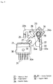
- FIG. 12 Conventionally, as a support structure of a magnetic head disposed in a magnetic card reader, for example, there is one as shown in FIG. 12.
- guide pins 92, 92 are provided at a fixed plate 91 provided at an apparatus main body side of a card reader, a movable plate 93 capable of moving vertically along the guide pins 92, 92 is provided, a magnetic head 96 is fitted to the movable plate 93 through a fastening member such as a screw 94 and a head holding bracket 95, and the magnetic head 96 is urged toward a side of a magnetic card 98 by urging means 97 such as a spring through the movable plate 93.
- the magnetic head 96 follows the magnetic card 98 and moves vertically together with the movable plate 93, and when a hole portion 99 in which the guide pin 92 is inserted is set an idle insert hole, the magnetic head 96 can be displaced in accordance with a warp of the magnetic card 98.
- An object of the present invention is to provide a support structure of a magnetic head in which a magnetic head having a function of being capable of following a warp or the like of a magnetic card can be easily attached and detached without using a fastening member such as a screw.
- Another object of the present invention is to provide a magnetic card reader having a support structure of a magnetic head superior in attachment/detachment properties.
- a support structure of a magnetic head according to the present invention is a support structure of a magnetic head for swingably supporting a magnetic head, which comprises a fixed member fixed to a fixed portion, a movable member rotatably supported by the fixed member and urged toward a fixed position, and support shafts protrusively provided at the front and back of the magnetic head, and in which groove portions for removably supporting the support shafts are formed at corresponding portions of the fixed member and the movable member in one of them in a vertical direction and in the other in a horizontal direction.
- the swing direction of the magnetic head can be set in a card width direction orthogonal to a transfer direction of the magnetic card.
- the groove portion in the vertical direction can be formed at a side of the fixed member and the groove portion in the horizontal direction can be formed at a side of the movable member.
- the magnetic head when the movable member rotatably supported by the fixed member is rotated in the direction opposite to the fixed position against an urging force, since the support shafts at the side of the magnetic head can be attached to and detached from the groove portions, the magnetic head can be easily attached and detached without using a fastening member such as a screw.
- the magnetic head since the magnetic head is rotatably supported by the support shafts, as supporting points, protrusively provided at the front and back thereof, it becomes rotatable correspondingly to the width direction of the magnetic card, and can cope with a warp of the magnetic card.
- the movable member is made C-shaped.
- a magnetic card reader of the present invention includes the support structure of the magnetic head of the above structure.
- the magnetic card reader superior in followingness to a magnetic card and in attachment/detachment properties of the magnetic head.
- FIG. 1 shows a magnetic card reader including a support structure of a magnetic head, and in FIG. 1, this magnetic card reader 11 is constructed such that transfer rollers 14, 14, 15, 15, 16, 16 are provided at upper and lower opposite positions of a card transfer line 13 formed in a card reader main body 12, and a magnetic card A is reversibly transferred along the card transfer line 13 from an exit/inlet portion 17 of the magnetic card reader 11.
- a press roller 18 and a transfer roller 19 are provided to be vertically opposite to each other between the foregoing transfer rollers 15 and 16, and a magnetic head unit 20 is provided at the side of the transfer roller 19, that is, the lower side of the card transfer line 13.
- the magnetic head unit 20 includes a magnetic head 21, and is constructed such that reading, writing, and erasing of magnetic information with respect to a magnetic recording medium of the magnetic card A is executed by this magnetic head 21.
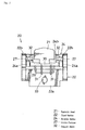
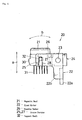
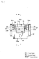
- the magnetic head unit 20 is constructed as shown in a front view of FIG. 2, a plan view of FIG. 3, and a side view of FIG. 4. First, a support structure of a magnetic head in a state where the magnetic head 21 is taken away will be described with reference to FIGS. 5, 6 and 7.
- the support structure of the magnetic head includes a fixed member 22 fixed to the card reader main body 12 as a fixed portion, and a movable member 24 rotatably supported by the fixed member 22 by using a support shaft 23.
- the fixed member 22 includes a substantially flat base portion 22a, and reversed L-shaped side plate portions 22b, 22b extending forward from this base portion 22a at right angles, and the support shaft 23 is extended between corner portions of the reversed L-shaped side plate portions 22b, 22b.
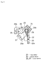
- the reversed L-shaped side plate portion 22b includes an upper horizontal portion and a lower vertical portion as shown in FIG. 7, and a vertical direction groove portion 25 is formed in a front end portion of the horizontal portion. This groove portion 25 is directed in the vertical direction, and its lower portion is open.
- cylindrical stoppers 26, 26 opposite to each other are integrally formed at upper sides of front-back direction intermediate portions of the horizontal portions of the side plate portions 22b, this stopper 26 may have a prismatic shape.
- movable member 24 a base member of which is fixed to the support shaft 23, a pair of arm portions 24a, 24a are integrally coupled by a coupling portion 24b, and the movable member is made C-shaped when seen on a plane.
- groove portions 27, 27 extending in the horizontal direction are formed at idle end sides of the arm portions 24a, 24a.
- the groove portion 27 is such a groove portion that its tip end is open, and in this embodiment, a taper portion is continuously provided at the tip end of the groove 27, and the insertion operationality of the magnetic head 21 is improved.
- a concave engagement portion 28 is formed at a portion corresponding to the stopper 26 at the side of the fixed member 22.
- a spring 29 for spring-urging the movable member 24 toward the fixed position is provided at the support shaft 23.
- the movable member 24 is structured to be rotatable with the support shaft 23 as the supporting point, a rotating operation can be made from the fixed position of FIG. 7 to a magnetic head attachment/detachment position of FIG. 8 against the spring force of the spring 29 as urging means.
- a head body holding bracket 30 (hereinafter simply referred to as a bracket) is fixed, and lead terminals 31 of the magnetic head 21 are protruded downward from an opening portion 30a of the bracket 30.
- a pair of support shafts 32 are protrusively fixed to the front and back of the bracket 30 correspondingly to the front-back direction (direction along the transfer direction of the magnetic card A) of the magnetic head 21.
- the movable member 24 at the fixed position shown in FIG. 7 is rotated around the support shaft 23 as the supporting point by the depressing operation toward the magnetic head attachment/detachment position of FIG. 8 against the spring force (urging force) of the spring 29.
- the pair of support shafts 32, 32 are inserted in the horizontal direction grooves 27, 27 of the pair of arm portions 24a, 24a of the movable member 24.
- the magnetic head 21 is swingable around the pair of supporting shafts 32, 32 as the supporting points in the width direction of the magnetic card A, and the pair of supporting shafts 32, 32 are supported by both the intersecting groove portions 25, 27 in a state where they are prevented from falling out. Further, the magnetic head 21 is held to be vertically movable through the movable member 24, and an urging load by the spring 29 is added to the magnetic head 21 at the time of downward movement of the magnetic head 21.
- a hole portion 33 for fixing the magnetic head unit 20 to a predetermined portion of the card reader main body 12 is formed in the base portion 22a of the fixed member 22, and the magnetic head unit 20 is fixed to the predetermined portion of the card reader main body 12 by using a fitting member (not shown) to be inserted in the hole portion 33.
- the magnetic head 21 and the bracket 30 are depressed from the fixed position shown in FIG. 11, and at the magnetic head attachment/detachment position where the intersection state of the respective groove portions 25 and 27 disappears as shown in FIG. 10, when the pair of supporting shafts 32, 32 are pulled out of the horizontal direction groove portions 27 of the movable member 24 through the magnetic head 21 and the bracket 30, the magnetic head 21 can be taken away as shown in FIG. 9.
- the support structure of the magnetic head of the embodiment is the support structure of the magnetic head 21 for supporting the magnetic head 21 swingably (see a direction of an arrow a of FIG. 4 and a direction of an arrow b), which comprises the immovable fixed member 22 fixed to the card reader main body 12 as the apparatus main body, the movable member 24 rotatably supported by the fixed member 22 and urged toward the fixed position (see FIGS.
- the magnetic head 21 since the magnetic head 21 is rotatably supported by the supporting shafts 32, as the supporting points, protrusively provided at the front and back thereof, it becomes rotatable (rotatable in the direction of the arrow b shown in FIG. 4) correspondingly to the width direction of the magnetic card A, and can cope with the warp of the magnetic card A.
- the movable member 24 is made C-shaped when seen on the plane as shown in FIGS. 3 and 6. It is possible to prevent the magnetic head 21 from varying in the card transfer front-back direction by the C-shaped structure of the movable member 24.
- the magnetic card reader 11 (see FIG. 1) of the embodiment includes the support structure of the magnetic head 21 of the above structure, the magnetic card reader superior in the followingness to the magnetic card A and in the attachment/detachment properties of the magnetic head 21 can be constructed, and can be used to be incorporated in various apparatuses, for example, an automatic teller machine requiring readout and/or writing of magnetic information to the magnetic card A, the so-called ATM and the like.
- the respective components of the support shaft 23, the movable member 24, the magnetic head 21, the bracket 30, and the support shaft 32 are fitted to the fixed member 22 as the vertical guide part, these components can be formed into a unit with a small space and compactness.
- the vertical direction groove portion of the present invention corresponds to the groove portion 25 at the side of the fixed member 22 (head fixing bracket member) of the embodiment, and similarly in the following, the horizontal direction groove portion corresponds to the groove portion 27 at the side of the movable member 24 (rotating arm member for holding the head).
- the present invention is not limited to the foregoing embodiment.
- a magnetic head having a function of being capable of following a warp or the like of a magnetic card can be easily attached and detached without using a fastening member such as a screw.
Landscapes
- Adjustment Of The Magnetic Head Position Track Following On Tapes (AREA)
- Supporting Of Heads In Record-Carrier Devices (AREA)
- Recording Or Reproducing By Magnetic Means (AREA)
Abstract
Description
Claims (3)
- A support structure of a magnetic head for swingably supporting a magnetic head, comprising:wherein groove portions for removably supporting the support shafts are formed at corresponding portions of the fixed member and the movable member in one of them in a vertical direction and in the other in a horizontal direction.a fixed member fixed to a fixed portion;a movable member rotatably supported by the fixed member and urged toward a fixed position; andsupport shafts protrusively provided at a front and a back of the magnetic head,
- A support structure of a magnetic head according to claim 1, wherein the movable member is made C-shaped.
- A magnetic card reader comprises a support structure of a magnetic head according to claim 1 or 2.
Applications Claiming Priority (2)
| Application Number | Priority Date | Filing Date | Title |
|---|---|---|---|
| JP2000307501A JP3664644B2 (en) | 2000-10-06 | 2000-10-06 | Magnetic head support structure and magnetic card reader |
| JP2000307501 | 2000-10-06 |
Publications (3)
| Publication Number | Publication Date |
|---|---|
| EP1195747A2 true EP1195747A2 (en) | 2002-04-10 |
| EP1195747A3 EP1195747A3 (en) | 2004-09-22 |
| EP1195747B1 EP1195747B1 (en) | 2008-12-17 |
Family
ID=18788005
Family Applications (1)
| Application Number | Title | Priority Date | Filing Date |
|---|---|---|---|
| EP01308231A Expired - Lifetime EP1195747B1 (en) | 2000-10-06 | 2001-09-27 | Support structure of a magnetic head and magnetic card reader |
Country Status (6)
| Country | Link |
|---|---|
| US (1) | US6927928B2 (en) |
| EP (1) | EP1195747B1 (en) |
| JP (1) | JP3664644B2 (en) |
| AT (1) | ATE418138T1 (en) |
| DE (1) | DE60137006D1 (en) |
| ES (1) | ES2317877T3 (en) |
Cited By (1)
| Publication number | Priority date | Publication date | Assignee | Title |
|---|---|---|---|---|
| EP2273423A3 (en) * | 2009-05-22 | 2011-11-02 | Hitachi-Omron Terminal Solutions, Corp. | Supporting apparatus for a magnetic head and card processing apparatus |
Families Citing this family (8)
| Publication number | Priority date | Publication date | Assignee | Title |
|---|---|---|---|---|
| US20070152051A1 (en) * | 2005-11-15 | 2007-07-05 | Schulz Christian E | Fluid ingress resistant magnetic stripe reader assembly |
| JP4877479B2 (en) * | 2006-02-28 | 2012-02-15 | 三和ニューテック株式会社 | Guide for magnetic head |
| US7753275B2 (en) * | 2007-09-17 | 2010-07-13 | Verifone, Inc. | Magnetic card reader, especially for point of sale terminals |
| WO2015181957A1 (en) * | 2014-05-30 | 2015-12-03 | 日立オムロンターミナルソリューションズ株式会社 | Magnetic head support device and card-processing device |
| JP5849194B1 (en) * | 2014-07-31 | 2016-01-27 | パナソニックIpマネジメント株式会社 | Information processing apparatus and transaction terminal apparatus |
| US9436856B2 (en) | 2014-12-23 | 2016-09-06 | Verifone, Inc. | Magnetic stripe card reader |
| FR3037689B1 (en) * | 2015-06-16 | 2017-07-14 | Ingenico Group | PIECE FOR MAINTAINING A MAGNETIC READING HEAD |
| US9721124B1 (en) | 2016-02-03 | 2017-08-01 | Verifone, Inc. | Magnetic card reader |
Family Cites Families (10)
| Publication number | Priority date | Publication date | Assignee | Title |
|---|---|---|---|---|
| US4167664A (en) * | 1978-01-20 | 1979-09-11 | Amp Incorporated | Adjustable read head assembly |
| US4375071A (en) * | 1980-10-20 | 1983-02-22 | Amp Incorporated | Mounting means for magnetic read head |
| JPS589262A (en) * | 1981-07-08 | 1983-01-19 | Nippon Denso Co Ltd | Magnetic card reader |
| FR2522430B1 (en) * | 1982-02-26 | 1987-11-20 | Europ Composants Electron | MAGNETIC READ AND / OR WRITE DEVICE |
| JP3113691B2 (en) * | 1991-03-30 | 2000-12-04 | アマノ株式会社 | Magnetic card reader with head reversal function |
| US5270523A (en) * | 1992-01-30 | 1993-12-14 | Uniform Industrial Corp. | Plate spring for mounting a magnetic stripe card reader's magnetic head |
| DE69313889T2 (en) * | 1992-02-13 | 1998-01-15 | Fujitsu Ltd | Ticket printer |
| GB2297417A (en) * | 1995-01-28 | 1996-07-31 | Thorn Transit Systems Int | A device for removably attaching a read or write head |
| JPH1063790A (en) * | 1996-08-13 | 1998-03-06 | Nippon Conlux Co Ltd | Magnetic head installation device for card reader/writer |
| US6342982B1 (en) * | 1998-08-31 | 2002-01-29 | Matsushita Electric Industrial Co., Ltd. | Card reader |
-
2000
- 2000-10-06 JP JP2000307501A patent/JP3664644B2/en not_active Expired - Fee Related
-
2001
- 2001-09-27 EP EP01308231A patent/EP1195747B1/en not_active Expired - Lifetime
- 2001-09-27 ES ES01308231T patent/ES2317877T3/en not_active Expired - Lifetime
- 2001-09-27 AT AT01308231T patent/ATE418138T1/en not_active IP Right Cessation
- 2001-09-27 DE DE60137006T patent/DE60137006D1/en not_active Expired - Lifetime
- 2001-10-03 US US09/969,091 patent/US6927928B2/en not_active Expired - Lifetime
Cited By (1)
| Publication number | Priority date | Publication date | Assignee | Title |
|---|---|---|---|---|
| EP2273423A3 (en) * | 2009-05-22 | 2011-11-02 | Hitachi-Omron Terminal Solutions, Corp. | Supporting apparatus for a magnetic head and card processing apparatus |
Also Published As
| Publication number | Publication date |
|---|---|
| ES2317877T3 (en) | 2009-05-01 |
| JP3664644B2 (en) | 2005-06-29 |
| JP2002117513A (en) | 2002-04-19 |
| DE60137006D1 (en) | 2009-01-29 |
| EP1195747B1 (en) | 2008-12-17 |
| EP1195747A3 (en) | 2004-09-22 |
| US20020093749A1 (en) | 2002-07-18 |
| ATE418138T1 (en) | 2009-01-15 |
| US6927928B2 (en) | 2005-08-09 |
Similar Documents
| Publication | Publication Date | Title |
|---|---|---|
| US4628386A (en) | Magnetic reading and/or writing head support assembly | |
| EP1195747B1 (en) | Support structure of a magnetic head and magnetic card reader | |
| US20010036060A1 (en) | Device unit housing apparatus | |
| US10026025B2 (en) | Card reader | |
| US20060211288A1 (en) | Card reader and writer | |
| JP4606127B2 (en) | Game board fixing device | |
| JPH02300031A (en) | Paper supply mechanism for image forming device | |
| JPS6117546Y2 (en) | ||
| KR900002067Y1 (en) | Cassette eject unit of tape recorder | |
| JP2789812B2 (en) | Cassette holder support structure | |
| JPH042448Y2 (en) | ||
| JP2806906B2 (en) | Portable personal computer | |
| JP2589406B2 (en) | Fixing device | |
| JP2002074272A (en) | Ic card processor | |
| JP3567201B2 (en) | IC card processing device | |
| JP2008235217A (en) | Clip type connector | |
| JP4397169B2 (en) | Paper holder | |
| EP1195709A2 (en) | IC contact unit and IC card reader | |
| EP1037160A2 (en) | A reading and writing device for an ic card | |
| JPH0355562Y2 (en) | ||
| JP2000272199A (en) | Handle guidance device for printing machine with portable handle | |
| JP2002074273A (en) | Ic card processor | |
| JPH0716208Y2 (en) | Time recorder printing device | |
| JPH0566768U (en) | Memory card dropout prevention device | |
| JPS6148075A (en) | Card reader |
Legal Events
| Date | Code | Title | Description |
|---|---|---|---|
| PUAI | Public reference made under article 153(3) epc to a published international application that has entered the european phase |
Free format text: ORIGINAL CODE: 0009012 |
|
| AK | Designated contracting states |
Kind code of ref document: A2 Designated state(s): AT BE CH CY DE DK ES FI FR GB GR IE IT LI LU MC NL PT SE TR |
|
| AX | Request for extension of the european patent |
Free format text: AL;LT;LV;MK;RO;SI |
|
| PUAL | Search report despatched |
Free format text: ORIGINAL CODE: 0009013 |
|
| AK | Designated contracting states |
Kind code of ref document: A3 Designated state(s): AT BE CH CY DE DK ES FI FR GB GR IE IT LI LU MC NL PT SE TR |
|
| AX | Request for extension of the european patent |
Extension state: AL LT LV MK RO SI |
|
| RIC1 | Information provided on ipc code assigned before grant |
Ipc: 7G 11B 5/50 B Ipc: 7G 11B 5/48 A |
|
| 17P | Request for examination filed |
Effective date: 20041108 |
|
| AKX | Designation fees paid |
Designated state(s): AT BE CH CY DE DK ES FI FR GB GR IE IT LI LU MC NL PT SE TR |
|
| RAP1 | Party data changed (applicant data changed or rights of an application transferred) |
Owner name: HITACHI-OMRON TERMINAL SOLUTIONS, CORP. |
|
| GRAP | Despatch of communication of intention to grant a patent |
Free format text: ORIGINAL CODE: EPIDOSNIGR1 |
|
| GRAS | Grant fee paid |
Free format text: ORIGINAL CODE: EPIDOSNIGR3 |
|
| GRAA | (expected) grant |
Free format text: ORIGINAL CODE: 0009210 |
|
| AK | Designated contracting states |
Kind code of ref document: B1 Designated state(s): AT BE CH CY DE DK ES FI FR GB GR IE IT LI LU MC NL PT SE TR |
|
| REG | Reference to a national code |
Ref country code: GB Ref legal event code: FG4D |
|
| REG | Reference to a national code |
Ref country code: CH Ref legal event code: EP |
|
| REG | Reference to a national code |
Ref country code: IE Ref legal event code: FG4D |
|
| REF | Corresponds to: |
Ref document number: 60137006 Country of ref document: DE Date of ref document: 20090129 Kind code of ref document: P |
|
| REG | Reference to a national code |
Ref country code: SE Ref legal event code: TRGR |
|
| REG | Reference to a national code |
Ref country code: ES Ref legal event code: FG2A Ref document number: 2317877 Country of ref document: ES Kind code of ref document: T3 |
|
| PG25 | Lapsed in a contracting state [announced via postgrant information from national office to epo] |
Ref country code: FI Free format text: LAPSE BECAUSE OF FAILURE TO SUBMIT A TRANSLATION OF THE DESCRIPTION OR TO PAY THE FEE WITHIN THE PRESCRIBED TIME-LIMIT Effective date: 20081217 |
|
| PG25 | Lapsed in a contracting state [announced via postgrant information from national office to epo] |
Ref country code: BE Free format text: LAPSE BECAUSE OF FAILURE TO SUBMIT A TRANSLATION OF THE DESCRIPTION OR TO PAY THE FEE WITHIN THE PRESCRIBED TIME-LIMIT Effective date: 20081217 |
|
| PG25 | Lapsed in a contracting state [announced via postgrant information from national office to epo] |
Ref country code: PT Free format text: LAPSE BECAUSE OF FAILURE TO SUBMIT A TRANSLATION OF THE DESCRIPTION OR TO PAY THE FEE WITHIN THE PRESCRIBED TIME-LIMIT Effective date: 20090518 Ref country code: AT Free format text: LAPSE BECAUSE OF FAILURE TO SUBMIT A TRANSLATION OF THE DESCRIPTION OR TO PAY THE FEE WITHIN THE PRESCRIBED TIME-LIMIT Effective date: 20081217 |
|
| PLBE | No opposition filed within time limit |
Free format text: ORIGINAL CODE: 0009261 |
|
| STAA | Information on the status of an ep patent application or granted ep patent |
Free format text: STATUS: NO OPPOSITION FILED WITHIN TIME LIMIT |
|
| PG25 | Lapsed in a contracting state [announced via postgrant information from national office to epo] |
Ref country code: DK Free format text: LAPSE BECAUSE OF FAILURE TO SUBMIT A TRANSLATION OF THE DESCRIPTION OR TO PAY THE FEE WITHIN THE PRESCRIBED TIME-LIMIT Effective date: 20081217 |
|
| 26N | No opposition filed |
Effective date: 20090918 |
|
| PG25 | Lapsed in a contracting state [announced via postgrant information from national office to epo] |
Ref country code: MC Free format text: LAPSE BECAUSE OF NON-PAYMENT OF DUE FEES Effective date: 20090930 |
|
| REG | Reference to a national code |
Ref country code: CH Ref legal event code: PL |
|
| PG25 | Lapsed in a contracting state [announced via postgrant information from national office to epo] |
Ref country code: IE Free format text: LAPSE BECAUSE OF NON-PAYMENT OF DUE FEES Effective date: 20090927 |
|
| PG25 | Lapsed in a contracting state [announced via postgrant information from national office to epo] |
Ref country code: LI Free format text: LAPSE BECAUSE OF NON-PAYMENT OF DUE FEES Effective date: 20090930 Ref country code: CH Free format text: LAPSE BECAUSE OF NON-PAYMENT OF DUE FEES Effective date: 20090930 Ref country code: GR Free format text: LAPSE BECAUSE OF FAILURE TO SUBMIT A TRANSLATION OF THE DESCRIPTION OR TO PAY THE FEE WITHIN THE PRESCRIBED TIME-LIMIT Effective date: 20090318 |
|
| PG25 | Lapsed in a contracting state [announced via postgrant information from national office to epo] |
Ref country code: LU Free format text: LAPSE BECAUSE OF NON-PAYMENT OF DUE FEES Effective date: 20090927 |
|
| PG25 | Lapsed in a contracting state [announced via postgrant information from national office to epo] |
Ref country code: TR Free format text: LAPSE BECAUSE OF FAILURE TO SUBMIT A TRANSLATION OF THE DESCRIPTION OR TO PAY THE FEE WITHIN THE PRESCRIBED TIME-LIMIT Effective date: 20081217 |
|
| PG25 | Lapsed in a contracting state [announced via postgrant information from national office to epo] |
Ref country code: CY Free format text: LAPSE BECAUSE OF FAILURE TO SUBMIT A TRANSLATION OF THE DESCRIPTION OR TO PAY THE FEE WITHIN THE PRESCRIBED TIME-LIMIT Effective date: 20081217 |
|
| REG | Reference to a national code |
Ref country code: FR Ref legal event code: PLFP Year of fee payment: 16 |
|
| PGFP | Annual fee paid to national office [announced via postgrant information from national office to epo] |
Ref country code: NL Payment date: 20160810 Year of fee payment: 16 |
|
| PGFP | Annual fee paid to national office [announced via postgrant information from national office to epo] |
Ref country code: GB Payment date: 20160921 Year of fee payment: 16 Ref country code: DE Payment date: 20160920 Year of fee payment: 16 Ref country code: IT Payment date: 20160921 Year of fee payment: 16 |
|
| PGFP | Annual fee paid to national office [announced via postgrant information from national office to epo] |
Ref country code: SE Payment date: 20160914 Year of fee payment: 16 Ref country code: FR Payment date: 20160816 Year of fee payment: 16 |
|
| PGFP | Annual fee paid to national office [announced via postgrant information from national office to epo] |
Ref country code: ES Payment date: 20160810 Year of fee payment: 16 |
|
| REG | Reference to a national code |
Ref country code: DE Ref legal event code: R119 Ref document number: 60137006 Country of ref document: DE |
|
| REG | Reference to a national code |
Ref country code: SE Ref legal event code: EUG |
|
| REG | Reference to a national code |
Ref country code: NL Ref legal event code: MM Effective date: 20171001 |
|
| GBPC | Gb: european patent ceased through non-payment of renewal fee |
Effective date: 20170927 |
|
| PG25 | Lapsed in a contracting state [announced via postgrant information from national office to epo] |
Ref country code: NL Free format text: LAPSE BECAUSE OF NON-PAYMENT OF DUE FEES Effective date: 20171001 |
|
| REG | Reference to a national code |
Ref country code: FR Ref legal event code: ST Effective date: 20180531 |
|
| PG25 | Lapsed in a contracting state [announced via postgrant information from national office to epo] |
Ref country code: DE Free format text: LAPSE BECAUSE OF NON-PAYMENT OF DUE FEES Effective date: 20180404 Ref country code: GB Free format text: LAPSE BECAUSE OF NON-PAYMENT OF DUE FEES Effective date: 20170927 |
|
| PG25 | Lapsed in a contracting state [announced via postgrant information from national office to epo] |
Ref country code: FR Free format text: LAPSE BECAUSE OF NON-PAYMENT OF DUE FEES Effective date: 20171002 Ref country code: IT Free format text: LAPSE BECAUSE OF NON-PAYMENT OF DUE FEES Effective date: 20170927 |
|
| REG | Reference to a national code |
Ref country code: ES Ref legal event code: FD2A Effective date: 20181017 |
|
| PG25 | Lapsed in a contracting state [announced via postgrant information from national office to epo] |
Ref country code: ES Free format text: LAPSE BECAUSE OF NON-PAYMENT OF DUE FEES Effective date: 20170928 |
|
| PG25 | Lapsed in a contracting state [announced via postgrant information from national office to epo] |
Ref country code: SE Free format text: LAPSE BECAUSE OF NON-PAYMENT OF DUE FEES Effective date: 20170928 |