EP1195655A2 - Intermediate transfer member - Google Patents
Intermediate transfer member Download PDFInfo
- Publication number
- EP1195655A2 EP1195655A2 EP01122614A EP01122614A EP1195655A2 EP 1195655 A2 EP1195655 A2 EP 1195655A2 EP 01122614 A EP01122614 A EP 01122614A EP 01122614 A EP01122614 A EP 01122614A EP 1195655 A2 EP1195655 A2 EP 1195655A2
- Authority
- EP
- European Patent Office
- Prior art keywords
- layer
- roller
- conformable
- poisson
- ratio
- Prior art date
- Legal status (The legal status is an assumption and is not a legal conclusion. Google has not performed a legal analysis and makes no representation as to the accuracy of the status listed.)
- Granted
Links
Images




Classifications
-
- G—PHYSICS
- G03—PHOTOGRAPHY; CINEMATOGRAPHY; ANALOGOUS TECHNIQUES USING WAVES OTHER THAN OPTICAL WAVES; ELECTROGRAPHY; HOLOGRAPHY
- G03G—ELECTROGRAPHY; ELECTROPHOTOGRAPHY; MAGNETOGRAPHY
- G03G15/00—Apparatus for electrographic processes using a charge pattern
- G03G15/14—Apparatus for electrographic processes using a charge pattern for transferring a pattern to a second base
- G03G15/16—Apparatus for electrographic processes using a charge pattern for transferring a pattern to a second base of a toner pattern, e.g. a powder pattern, e.g. magnetic transfer
- G03G15/1605—Apparatus for electrographic processes using a charge pattern for transferring a pattern to a second base of a toner pattern, e.g. a powder pattern, e.g. magnetic transfer using at least one intermediate support
- G03G15/162—Apparatus for electrographic processes using a charge pattern for transferring a pattern to a second base of a toner pattern, e.g. a powder pattern, e.g. magnetic transfer using at least one intermediate support details of the the intermediate support, e.g. chemical composition
-
- G—PHYSICS
- G03—PHOTOGRAPHY; CINEMATOGRAPHY; ANALOGOUS TECHNIQUES USING WAVES OTHER THAN OPTICAL WAVES; ELECTROGRAPHY; HOLOGRAPHY
- G03G—ELECTROGRAPHY; ELECTROPHOTOGRAPHY; MAGNETOGRAPHY
- G03G2215/00—Apparatus for electrophotographic processes
- G03G2215/01—Apparatus for electrophotographic processes for producing multicoloured copies
- G03G2215/0103—Plural electrographic recording members
- G03G2215/0119—Linear arrangement adjacent plural transfer points
Definitions
- This invention relates to electrostatography and, more particularly, to a reproduction method and apparatus that employs transfers of toner images to and from intermediate transfer members.
- an electrophotographic process a photoconductive element is initially electrically charged.
- An electrostatic latent image is first formed by image-wise exposing the photoconductive element using an exposure source such as a laser scanner or an LED array.
- the latent image is developed into a visible image by bringing the electrostatic latent image into close proximity to a developer such as contained in a magnetic brush or other known type of development station.
- the developer can be what is typically referred to as a single component developer containing toner particles.
- the developer can have two or more components with nonmarking magnetic carrier particles and marking non-magnetic toner particles.
- electrostatic latent images corresponding to the appropriate color are separately formed and developed.
- the resulting toner images are transferred to a receiver, such as a paper or a plastic sheet for example, preferably by using an electrostatic field to urge the toner in the direction of the receiver.
- a receiver such as a paper or a plastic sheet for example
- the electrostatic field is commonly applied in one of several manners. For example, charge can be sprayed on to the back of a receiver using a corona device. However, it is frequently preferable to use an electrically biased transfer roller to apply the field, especially in instances where color images are to be produced.
- the second nip can be formed in a variety of ways, such as utilizing a biased transfer drum wrapped in a tensioned, electrically biasable transport web to which a receiver sheet is attached, or by using a dielectric transport web and an electrically biasable backup transfer roller. Color images are produced by developing and transferring toner images corresponding to the appropriate color separations.
- color separations having cyan, magenta, yellow and black toners typically are used.
- Color separation toner images are commonly transferred sequentially, in a registered manner, to an ITM and, subsequently, the complete color toner image is transferred from the ITM to a receiver in one step.
- individual color toner separation images can be transferred to separate ITMs, or to different sections of a single ITM, and then transferred in register to a receiver in multiple steps.
- a toner image on a receiver is permanently fixed using known processes such as thermal or radiant fusing.
- a latent electrostatic image is created on a dielectric imaging member, e.g., by ionography or by electrified stylus or by other known means, and then toned.
- the resulting toner image which can be a color separation image, can then be transferred to an ITM, and subsequently transferred to a receiver and fused as described above.
- An electrographic press can include a sequential series of modules, each module having an electrographic dielectric imaging member and an ITM for generating and transferring a color separation toner image to a receiver.
- the nip is an engagement area of a roller under pressure with another member. This engagement area will result in some deformation. Pressure nips formed by rollers coated with elastomers are known to exhibit overdrive. Overdrive is the phenomena where the tangential speed of a roller within the nip engagement area is actually different than the tangential speed of the roller in an area not near the nip. Overdrive can be understood from a hypothetical consideration of a roller having an externally driven axle, frictionally driving a movable planar element having a nondeformable surface.
- ⁇ the nominal angular rotational rate of the roller around its axis (radians per unit time)
- ⁇ is determined principally by the roller materials effective Poisson's ratio and moduli, by the engagement and drag torque forces.
- the Poisson ratio, v of high polymers (those having a high molecular weight) approaches 0.5, and approaches zero for very soft polymeric foams. It has been shown in theoretical model computations by K. D. Stack, Nonlinear Finite Element Model of Axial Variation in Nip Mechanics with Application to Conical Rollers [Ph.D. Thesis, University of Rochester, Rochester, N.Y. (1995), FIGS.
- the deformable material should have a value of Poisson's ratio of about 0.3 in order to have negligible overdrive, i.e., ⁇ ⁇ 1.
- the circumference of the roller is greater than 2 ⁇ R, producing overdrive of the planar element with respect to the roller, i.e., the surface speed within the nip of the coated roller (and hence that of the planar element) is greater than v 0 .
- the circumference of the roller is less than 2 ⁇ R, producing underdrive of the planar element with respect to the roller, i.e., the surface speed is smaller than v 0 within the nip.
- a nondeformable planar element frictionally drives, with negligible drag
- a roller having ⁇ less than about 0.3 and causes it to rotate one can speak of overdrive of the roller with respect to the planar element because the surface speed of the driven roller far from the nip is faster than the speed of the planar element.
- a foam or sponge can include a "felted" material, as is well known in the art.
- Felted foams can be made, for example, by compressing under heat, typically uniaxially, an elastomeric, previously made foam, followed by cooling it under compression and then removing the compressive load.
- Felted foams have anisotropic mechanical properties. For example, both the Young's modulus and Poisson's ratio of a felted foam material made by uniaxial compression will be different along the direction of compression that lies in a plane at right angles to the direction of compression. Moreover, Poisson's ratio, which tends to be small for soft foams, can even take on negative values in felted foams or sponges.
- Overdrive associated with two materials in contact in a pressure nip can result in squirming and undesirable stick-slip behavior. Such behavior can adversely affect image quality when more than one intermediate transfer member is used to make a color print in a color reproduction machine, e.g., by degrading the mutual registration of color separation images if the amount of overdrive produced by each ITM roller varies from roller to roller, or, by causing toner smear.
- variations in overdrive from a given roller can occur axially or radially along the length of a transfer nip, such variations being produced, for example, by local changes in engagement, such as caused by runout, or by a lack of parallelism, or by variations of dimensions of the members forming a transfer nip.
- An electrophotographic printing press can include a number of modules, one module for each color separation.
- Each module includes, for example, a photoconductive drum and an ITM in the form of a drum, e.g., forming a cyan toner image in module 1, a magenta image in module 2, a yellow image in module 3, and a black image in module 4.
- Each photoconductive drum has a primary charging station, an exposure station using a digital writer such as a laser scanner or LED array, a developing station, and a transfer station having a pressure nip where toner is electrostatically transferred to an appropriately electrically biased ITM drum, and a cleaning station.
- a receiver sheet e.g., a paper sheet or a plastic transparency
- the individual color separation toner images are successively transferred in register, from the successive ITMs of each module, to a receiver, e.g., paper, in successive transfer stations.
- Each transfer station where a color toner image is transferred from an ITM to a receiver, includes a pressure nip formed with a suitably electrically biased transfer roller (backup roller) behind the receiver.
- a full-color toner image on a receiver is then sent to a fusing station where the toner is fused to the receiver.
- overdrive there is unregulated overdrive in the modules (the magnitude of overdrive can vary in degree from module to module) it is possible in principle to optimize registration (which is determined by the exact time of transfer from each ITM drum to receiver) by timing the writing of each latent image on each photoconductor drum, for example by sensing the location of an edge or a fiducial mark on a receiver sheet as it is transported from module to module.
- This can be costly, cumbersome and inconvenient.
- differential overdrive then radial and axial variations of overdrive along a nip cannot be compensated for in such a manner, and the result can be unwanted losses of registration (and possible localized image smearing) in portions of a toned print.
- significant drag forces result from the various contacting interfaces between drums and other elements in a module. These drag forces, which affect the amount of overdrive, can have time-dependent fluctuations which can also produce registration errors.
- compliant ITMs are disclosed, for example, in: Rimai et al., U.S. Patent No. 5,084,735; Ng et al., U.S. Patent No. 5,110,702; Zaretsky, U.S. Patent No. 5,187,526; Rimai et al, U.S. Patent No. 5,666,193; and Tombs et al., U.S. Patent No. 5,689,787.
- the benefits of employing compliant ITMs are well known, especially as pertaining to their use with small toner particles.
- Small toner particles are defined as toner particles having a mean volume weighted diameter of between 2 micrometers and 9 micrometers, as determined by a suitable commercial particle sizing device such as a Coulter Multisizer.
- a suitable commercial particle sizing device such as a Coulter Multisizer.
- a prior art compliant ITM such as cited above in U.S. Patent Nos.
- 5,084,735; 5,110,702; 5,187,526; 5,666,193; and 5,689,787 typically includes an elastomeric layer preferably between 1 mm and 25 mm in thickness, having a Young's modulus between 1 MPa and 50 MPa and having an electrical resistivity between 10 6 ohm-cm and 10 12 ohm-cm, preferably 10 7 ohm-cm to 10 9 ohm-cm. It is preferable that such a prior art compliant intermediate also include a relatively thin (0.1 mm to 20 mm thick) overcoat layer having a material whose Young's modulus is greater than 100 MPa.
- Young's modulus is determined on a macroscopic-size sample of the same material using standard techniques, such as by measuring the strain of the sample under an applied stress using a suitable commercial device such as an Instron Tensile Tester and extrapolating the slope of the curve back to zero applied stress.
- M. Toshio et al. in U.S. Patent No. 5,519,475, discloses a differential motion that produces a slip between a PC drum and an ITM in order to improve the transfer of toner.
- the embodiments disclosed employ gears to provide the differential motion.
- the invention of M. Toshio et al., in U.S. Patent No. 5,519,475 relates to a peripheral speed difference between PC and ITM in a range of 0.5% to 3.0%. See also Tanigawa et al., U.S. Patent No. 5,438,398.
- Tanigawa et al. in U.S. Patent No. 5,438,398, disclose an intermediate member having a metal pipe core covered by a single layer of an elastic material which can include a foam.
- the elastic material is 8 mm thick, contains dispersed carbon or zinc oxide or the like and has resistivity 10 5 ohm-cm - 10 11 ohm-cm.
- the elastic layer has 20° to 40° Asker C hardness.
- the transfer roller is relatively much harder, made of a conductive core and a thin outer layer of a fluorinated resin having thickness 20 micrometers - 100 micrometers.
- a roller which functions as an ITM for color imaging, whereby individual color toner images are successively electrostatically transferred to the ITM to build a full-color image on the ITM.
- a receiver sheet is passed through the same nip with the electric field direction in the nip reversed, thereby transferring the full-color toner image to the receiver, during which time the PC drum acts, in effect, as a transfer roller.
- the ITM has a metal core, an electrically conductive elastic layer having resistivity 10 3 ohm-cm - 10 6 ohm-cm, and a thin outer layer having resistivity 10 7 ohm-cm - 10 11 ohm-cm.
- the electrically conductive elastic layer can be a foamed EPDM (ethylene propylene diene monomer) layer having dispersed carbon particles to give a resistivity of 10 3 ohm-cm
- the outer layer can be a low surface energy material, e.g., polyvinylidene fluoride containing tin oxide and having a resistivity of 10 9 ohm-cm.
- the hardness of the ITM roller is 35° Asker C, i.e., the foam layer is quite soft and therefore significant overdrive is to be expected in a nip formed with the other, relatively hard, roller.
- overdrive sensitivity to engagement variations and other process noises, such as for example produced by runout such as produced by roller eccentricity or acentricity, or by a lack of parallelism or by variations of dimensions of the members or components of the members forming a transfer nip.
- ITM such that its overdrive (or underdrive) characteristics are insensitive to changes in drag, such as for example can be produced when a receiver sheet enters a second transfer nip.
- an ITM according to the invention provides a method and apparatus of reducing both overdrive and differential overdrive associated with an intermediate transfer member roller of an electrostatographic color reproduction machine.
- the main benefit is a reduced sensitivity to fluctuations of engagement associated with roller runout, mounting tolerance errors, and the like.
- the invention provides an improved registration of color separation toner images, and an improved fidelity of reproduction with minimal distortion of an original or input image to be reproduced.
- an intermediate transfer roller for use in electrostatography including a method and apparatus for an intermediate transfer roller for use in electrostatography wherein a rigid cylindrical core member is provided then surrounded by an elastically deformable structure having a Poisson's ratio in a range of 0.2 to 0.4.
- the elastically deformable structure surrounding the core member has a conformable layer surrounding the core member, a compliant blanket layer surrounding and adhered to the conformable layer, and a thin hard outer layer formed on the compliant blanket layer.
- a thin flexible electrically conductive electrode layer adhered to the conformable layer is also discussed.
- the invention discloses novel intermediate transfer members that are useful for full color electrostatography, and especially, full color electrophotography utilizing one or more single color toner images, whereby each single color toner image is formed on a primary image-forming member (PIFM) and transferred in a first transfer step to a novel intermediate transfer member (ITM) having a deformable structure having an effective or operational Poisson's ratio near about 0.3. Subsequently, the toner image is transferred in a second transfer step to a receiver, e.g., a paper or a plastic sheet.
- PIFM primary image-forming member
- ITM novel intermediate transfer member
- electrophotographic recording there can be used electrographic recording of each primary color image using stylus recorders or other known recording methods for recording a toner image on a PIFM which can include a dielectric member, the toner image to be transferred electrostatically via an ITM as described herein.
- a PIFM can include a web or a drum.
- single color toner images are sequentially transferred in registry to a receiver sheet carried on a moving transport web through a series of corresponding single color tandem modules.
- Each single color module includes a rotating compliant ITM roller and a counter-rotating PIFM roller.
- the moving transport web can frictionally drive the ITM roller, causing the ITM to rotate, while the ITM in turn can frictionally drive the PIFM, causing the PIFM to rotate.
- the compliant character of the ITM will tend to cause the ITM to be underdriven by a relatively unyielding transport web (backed by a roller), and will also tend to cause the ITM to overdrive a relatively hard PIFM.
- overdrive or underdrive
- the amounts of overdrive (or underdrive) in each module will tend to differ to some degree, inasmuch as there can be slightly different engagements between members or slightly different roller dimensions in the individual modules, e.g., arising from tolerance errors or ambient temperature differences.
- overdrive in a given nip can exhibit variations known as differential overdrive, which can occur axially or radially along the length of a transfer nip, and these variations can be caused, for example, by local changes in engagement, such as caused by runout, or by a lack of parallelism of roller axes, or by irregularities of the dimensions of the members forming a transfer nip.
- the invention is particularly useful for producing color images, especially full color images.
- a full color image e.g., from primary colored cyan, magenta, yellow, and black toners, or from other single color toners.
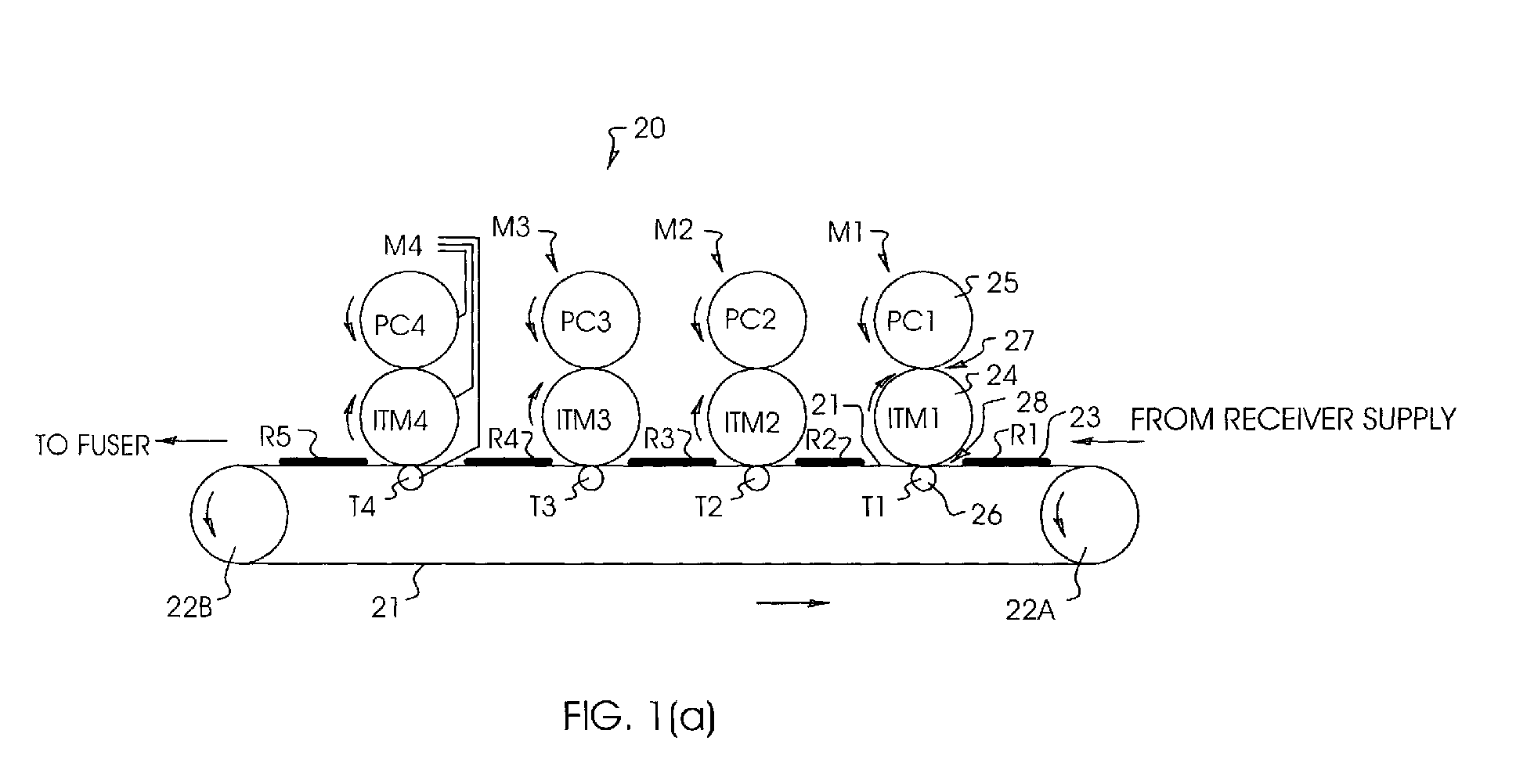
- a preferred embodiment of a four-module press is indicated by the numeral 20 in FIG. 1(a), wherein each module includes an ITM of the invention and is capable of producing an image with one of the single color toners. More or fewer than four modules can be used.
- a first module includes a PIFM in the form of a first photoconductive drum (PC1) 25 which could also be a roller, and a first intermediate transfer member (ITM1) 24 which can be either a drum or roller.
- the other modules are similarly constructed with each module including a photoconductive drum, an inventive ITM, and a transfer backup drum or roller, as for example indicated for Module 4 in FIG. 1(a).
- Module 1 produces for example a cyan toner image.
- a photoconductive drum 25 rotating counterclockwise as shown is charged by suitable charging means (not shown) and then image-wise exposed using an LED array, laser scanner, optical exposure, or other suitable means (not shown).
- the image is then developed by bringing the electrostatic latent-image bearing PC1 into proximity of an electrophotographic developer such as contained in a development station in the same module (not shown). It is preferable to use a so-called "two-component" developer wherein one of the components includes magnetic carrier particles and the other component includes the toner particles.
- the cyan toner image is then electrostatically transferred in a first transfer nip 27 to intermediate a first transfer member (ITM1) 24, which rotates clockwise.
- ITM1 first transfer member
- PC1 25 is subsequently cleaned in a cleaning station (not shown) before charging and imagewise to create another latent electrostatic image.
- a receiver sheet (R1) 23 is transported from a receiver supply unit (not shown) and adhered, preferably electrostatically, to a transport belt 21 which is moved to the left, e.g., by counterclockwise rotation of rollers 22A and 22B which are provided with a motor drive.
- the inventive ITM1 includes an elastically deformable surface structure having one or more layers, having an effective or operational Poisson's ratio between 0.2 and 0.4, preferably between 0.25 and 0.35, and more preferably between 0.28 and 0.32.
- the elastically deformable surface structure produces suitable nip contact widths to provide high efficiency transfers of toner, from PC1 to ITM1 and from ITM1 to the receiver R1.
- other single color toner images e.g., magenta, yellow and black
- modules M2, M3 and M4 are sequentially transferred in otherwise similar modules M2, M3 and M4 to the receiver as it is transported from one module to another. Additional modules can be added if desired.
- the cyan image is being transferred to R1 in M1
- other color separation images are being transferred to receivers R2, R3 and R4 in modules M2, M3 and M4, respectively.
- a completed full-color print, e.g., R5 is transported to a fuser in a fusing station (not shown) wherein the toner image is permanently fixed to the receiver.
- the transfer of the toner image transferred from an ITM to the receiver in a given module must be accomplished at a specific time.
- the specificity can be accomplished by adjusting the timing of the exposure used to form each of the electrostatic latent images (such as by using a fiducial mark laid down on a receiver) or by sensing the position of an edge of a receiver at a known time as it is transported through the machine at a known speed.
- the elastically deformable surface structure of an ITM of FIG. 1(a) can have a thin hard outer layer.
- the elastically deformable surface structure of an ITM of FIG. 1(a) can include a conformable layer, an optional thin flexible electrically conductive electrode layer adhered to the conformable layer, a compliant blanket layer surrounding and adhered to the electrode layer, and a thin hard outer layer coated on the blanket layer, wherein the Poisson's ratio of the conformable layer has a value less than 0.4, preferably in a range between 0.20 and 0.35, and the Poisson's ratio of the compliant blanket layer has a value between 0.4 and 0.5, preferably between 0.45 and 0.50. It is preferred that the compliant blanket layer be substantially incompressible.
- the elastically deformable surface structure of an ITM of FIG. 1(a) can be formed on a strengthening band to create a sleeve member which removably and replaceably non-adhesively surrounds and intimately contacts the core member.
- FIG. 9 shows a sketch of an ITM roller 90 in accordance with the present invention, having a set of descriptive markings, or indicia, on the outer surface of the roller.
- These indicia are envisioned as being used to give parametric information relative to the roller.
- the outer surface can correspond to an outer surface of a roller 90 having a sleeve member, in which case the outer surface of the roller is the outer surface of the sleeve member.
- the indicia are located in a small area 92" located on a portion 91A of the cylindrical surface close to an end of the roller.
- the indicia are contained in a small area 92' located on an end portion 91B of the roller, with area 92' preferably near the edge or rim (the individual layers including roller 90 are not shown).
- area 92' is preferably located on the edge of the sleeve.
- an indicia When an indicia is provided on a member directly underneath the sleeve member, it can also be useful to provide an opening or cutaway in the sleeve member to allow the indicia to be detected with the sleeve member in operational position.
- An enlarged view 92 of either of the small areas 92' or 92" illustrates that the descriptive indicia can be in the form of a bar code, as indicated by the numeral 93, which can be read, for example, by a scanner.
- the scanner can be mounted in an electrophotographic machine so as to monitor an inventive ITM roller, e.g., during operation of the machine or during a time when the machine is idle, or the scanner can be externally provided during installation of, or during maintenance of, an inventive roller.
- the indicia can be read, sensed or detected by an indicia detector 95.
- the analog or digital output of the indicia detector can be sent to a logic control unit (LCU) incorporated in an electrostatographic machine utilizing an inventive ITM roller, or it can be processed externally, e.g., in a portable computer during the installation or servicing of an inventive ITM roller, or it can be processed in any other suitable data processor.
- LCU logic control unit
- the indicia can be read optically, magnetically, or by means of a radio frequency.
- the indicia could include any suitable markings, including symbols and ordinary words, and can be color coded.
- the indicia could also be read visually or interpreted by eye.
- a color coded indicia on a roller could exist within a relatively large colored area which can be otherwise devoid of markings or other features making it readily interpreted by the eye to have a property as indicated by the color-coded roller.
- the indicia can be utilized to measure the wear rate of an inventive ITM roller, e.g., by providing a portion of the indicia having a predetermined wear rate.
- the wear rate of an indicia can be measured optically, e.g., by monitoring the reflection optical density of a portion of the indicia which is subjected to wear, or by other suitable means.
- Suitable materials for the indicia are for example inks, paints, magnetic materials, reflective materials, and the like, which are applied directly to the surface of the roller.
- the indicia can be located on a label that is adhered to the outer surface of the roller.
- the indicia could also be in raised form or produced by stamping with a die or by otherwise deforming a small local area on the outer surface of the roller, and the deformations can be sensed mechanically or otherwise detected or read using an indicia detector 95 in the form of a contacting probe or by other mechanical means.
- the outside diameter of a roller can be recorded so that nip width parameters can be accordingly adjusted.
- the date of manufacture of the roller can be recorded in the indicia for diagnostic purposes, so that the end of useful life of the roller could be estimated for timely replacement.
- Specific information for each given roller regarding the roller runout, e.g., as measured after manufacture, could also be recorded in the indicia.
- the information can be used to speed the calibration time of a registration system as explained below.
- the registration system might utilize a software algorithm that controls the speed of the start-of-line clock signal fed to an LED writehead.
- a separate start-of-line clock signal is used for each color module, each controlling the length of the color toner image of the respective color separation image produced by each module, thereby ensuring that the color toner image length is correct and uniform throughout the image.
- a toner image from a PC to an ITM it is preferable to transfer a toner image from a PC to an ITM by providing a suitable electric field for electrostatic transfer. This is most readily accomplished by electrically biasing the ITM and grounding a conductive layer situated under a photoconductive layer (or layers) on a PC, as is well known. Electrostatic transfer of the toner image from ITM to a receiver is most readily accomplished by applying a suitable electrical bias to a transfer roller so as to urge the toner to move from ITM to receiver.
- Another method of providing a suitable electric field for electrostatic transfer of toner from an ITM to a receiver is to apply a corona charge, of polarity opposite to that of the toner, to the rear surface of a receiver sheet as is well known in the art, whereby the need to bias the backup roller is obviated.
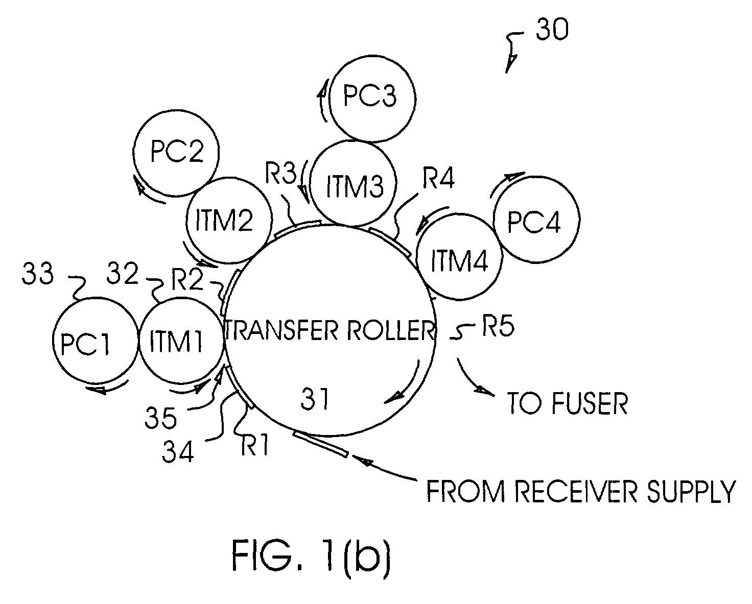
- FIG. 1(b) Another embodiment employing ITMs of the invention in an electrophotographic press is indicated by 30 in FIG. 1(b), which includes a large electrically biased transfer roller 31, which could also be a drum.
- Four individual color modules are arranged in tandem around transfer roller 31, each module having a PC drum or roller and an ITM drum or roller provided with an elastically deformable surface structure having an effective or operational Poisson's ratio between 0.2 and 0.4, preferably between 0.25 and 0.35.
- a first module, labeled M1 includes a photoconductive drum 33 labeled PC1 and an intermediate transfer member 32 labeled ITM1.
- the PCs and ITMs of the other modules are similarly appropriately labeled.
- a single color toner image e.g., cyan
- module M1 A single color toner image, e.g., cyan
- R1 a receiver sheet 34, labeled R1
- R1 A single color toner image
- R1 passes through transfer nip 35 after being transported from a supply unit (not shown).
- the transfer drum 31 rotates in the direction of the indicated arrow, color separation toner images are successively transferred, on top of each other and in registry, from each ITM to a receiver sheet in modules M2, M3 and M4.
- receivers R2, R3 and R4 When a first toner color separation image is being transferred in module M1 to receiver R1, other color separation toner images are being transferred to receivers R2, R3 and R4, while receiver R5 which carries a composite full color image is on its way to a fuser in a fusing station (not shown).
- More or fewer than four modules can be used. This type of electrophotographic press is less preferred, because the paper path is not straight and also because the orientations of the development stations with respect to the vertical pull of gravity cannot be the same, requiring costly and significant adaptations of the individual development stations.
- FIG. 1(c) shows yet another embodiment of a multimodular electrophotographic press, shown as having four modules and indicated by 40, that can utilize ITMs of the invention. More or fewer than four modules can be used.
- a large inventive ITM 41 rotates clockwise in the direction of the arrow past a series of modules M1, M2, M3, and M4 each including a corresponding photoconductor PC1, PC2, PC3, and PC4 rotating counterclockwise.
- the ITM 41 is a drum or roller and includes an elastically deformable surface structure having an effective or operational Poisson's ratio between 0.2 and 0.4, preferably between 0.25 and 0.35.
- a first color separation toner image e.g., cyan
- roller or drum 42 labeled PC1 is transferred in nip 45 from PC1 to ITM 41.
- a second color separation toner image e.g., magenta
- the full-color image is subsequently electrostatically transferred in nip 46 to a receiver sheet 44 transported from a supply unit (not shown), using electrically biased transfer backup roller 43.
- this type of electrophotographic press is simpler and gives easier registration than press 30 in FIG. 1(b), it is less preferred for similar reasons, as well as for the additional reason that good image quality is more difficult to attain when a 4-color toner stack has to be created without disruptions and then co-transferred intact to a receiver.
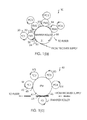
- ITM 10 includes a rigid core member 11, a conformable layer 12 surrounding core member 11, an optional thin, flexible conductive electrode layer 15 adhered to conformable layer 12, an elastomeric compliant blanket layer 13 surrounding and adhered to the electrode layer 15 (or adhered to the conformable layer 12 if layer 15 is absent), and a thin hard outer layer 14 formed on the elastomeric compliant layer 13.
- layer thicknesses are not drawn to scale but for illustrative purposes.
- Core member 11 preferably includes a metal such as, for example, aluminum or other suitable metal, in the form of a pipe, which can include internal strengthening members such as struts and the like. Core 11 is cylindrical and centered on its axis of rotation, meaning it preferably has a runout of less than 80 micrometers, and more preferably less than 20 micrometers.
- the conformable layer 12 preferably includes a closed cell elastomeric foamed material, although an open cell elastomeric foam or sponge can be useful in some applications.
- the foam or sponge layer 12 can furthermore have a "felted" material.
- the thickness of the conformable layer 12 is preferably between 3 mm and 25 mm, and more preferably, between 5 mm and 10 mm.
- the layer 15 is preferably connected to a source of voltage or current in order to apply an electric field to effect electrostatic transfer of a toner image to or from ITM 10.
- the optional conductive layer 15 is not included, and the core member 11 includes an electrically conductive surface which is connected to a source of voltage or current.
- the conformable layer 12 is preferably provided with a suitable conductivity which, for example, can be obtained by dispersing finely divided carbon or other conductive particles within the continuous phase, or by using suitable antistatic materials dissolved in the continuous phase.
- the electrical resistivity of the conformable layer 12 is preferably less than 10 8 ohm-cm and more preferably less than 10 7 ohm-cm.
- the conformable layer 12 is suitably conductive, it can be preferable to include a conductive layer 15 which is electrically floated, thereby providing an equipotential and hence guaranteeing a highly uniform electric field inside compliant blanket layer 13.
- the conformable layer 12 preferably includes a polyurethane, a silicone resin, a polyimide, or any other suitable elastomer, and can for example include a copolymer or a polymer blend.
- Layer 12 can also include a particulate filler or other addenda to modify the electrical or mechanical properties, as is well known.
- Layer 12 should preferably have uniform thickness, and can be smoothed, e.g., by freezing and grinding, or by other suitable means, prior to application of layers 15 and 13 by suitable methods, e.g., coating.
- a foam or sponge layer can be wrapped around a core 11 to form conformable layer 12, but wrapping is not the most preferred embodiment because it presents a problem of attaining a smooth joint.
- conformable layer 12 can be formed by a chemically foamed material from suitable monomers on to core 11 in a cylindrical mold and then cured, or it can be made and located on core 11 by any other suitable methods or means.
- a mold having two concentric cylinders can be used to make the compliant elastomeric layer 13 in the form of a tube, after which the inner cylinder is demolded, a conductive layer 15 is optionally applied to the interior surface of the tube, a core 11 is inserted with its axis coincident with the axis of the outer cylinder, and a foam layer 12 is made in the space between the core and the inner surface of layer 13 by chemical foaming from suitable monomers and curing, after which the outer cylinder of the mold is demolded.
- the solid phase of foam layer 12 preferably has a Young's Modulus in a range 1 x 10 6 Pa to 2 x 10 9 Pa, and more preferably, 2 x 10 6 Pa to 5 x 10 8 Pa.
- Young's modulus of an elastically deformable foam is usually much less than that of its solid phase, on account of the presence of the gaseous phase.
- a typical foam or sponge can have a Young's modulus which is an order of magnitude smaller than that of the solid phase.
- Young's modulus of a foam (or of any material, including a laminated or layered material) is determined on a macroscopic-size sample using a standard technique, such as by measuring the strain of the sample along a given direction under an applied stress using a suitable commercial device such as an Instron Tensile Tester and extrapolating the slope of the curve back to zero applied stress.
- Poisson's ratio of a foam can be readily measured in a macroscopic-size piece by applying a compressive stress along one direction of a bar shaped sample of the foam, e.g., the z-axis in a Cartesian coordinate system, measuring a corresponding transverse strain parallel to the x-axis (or y-axis), and dividing the x-axis strain by the z-axis strain.
- a compressive stress along one direction of a bar shaped sample of the foam, e.g., the z-axis in a Cartesian coordinate system
- measuring a corresponding transverse strain parallel to the x-axis (or y-axis) dividing the x-axis strain by the z-axis strain.
- the x- and y-strains will be identical, but for felted foams, for example, this will generally not be the case.
- the compliant blanket layer 13 can be applied to the conformable layer 12 or the outer conductive surface of core 11 (depending on the specific embodiment as detailed above) in the form of a tube.
- the tube can be a thermally shrink-wrapped tube, although this is not the most preferred embodiment because of limitations on materials, thermal shrink wrapping is clearly envisioned within the confines of the present invention.
- compliant blanket layer 13 can be an elastomeric skin layer produced as a result of foaming in creating conformable layer 12 on to core 11 in a cylindrical mold, but this is also generally less preferred because it is generally desirable to make the conformable layer 12 and the compliant blanket layer 13 from different materials.
- an elastomeric layer can be coated directly on the skin of compliant blanket layer 13.
- Compliant blanket layer 13 can be made, for example, by either a solvent coating it or a dip coating it on top of the conformable layer 12, or by any other suitable method or means.
- a thin subbing or barrier layer can be required between conformable layer 12 and compliant blanket layer 13 [not shown in FIG. 2 (a)] in order to facilitate coating of compliant blanket layer 13.
- the compliant layer 13 preferably has thickness in a range of 0.5 mm to 5 mm, preferably 1 mm to 2 mm.
- Compliant blanket layer 13 has an electrical resistivity which is typically one or more orders of magnitude higher than the resistivity of the conformable layer 12.
- the electrical resistivity of compliant blanket layer 13 is in a range of 10 7 ohm-cm to 10 11 ohm-cm, preferably 10 8 ohm-cm to 10 9 ohm-cm.
- Compliant blanket layer 13 can include a particulate filler or an antistat to modify the mechanical or electrical properties, as is well known.
- the compliant blanket layer 13, inclusive of any addenda such as for example antistats or other addenda, has a Young's modulus in a range 0.5 MPa to 50 MPa, preferably 1 MPa to 10 MPa.
- the compliant blanket layer 13 preferably includes a polyurethane material, but it could also be made from any suitable elastomer.
- the outer layer 14 in FIG. 2 (a) is thin and relatively hard, one purpose of which is to effectively prevent toner embodiment, thereby enhancing electrostatic transfer of toner particles to a receiver. Another purpose is to render the roller 10 more readily cleanable and less abradable in a cleaning station. It is preferable that outer layer 14 be relatively thin, 0.1 micrometer to 20 micrometers thick, having a material whose Young's modulus is greater than 50 MPa and preferably greater than 100 MPa. Layer 14 preferably has a high resistivity, at least as high as that of compliant blanket layer 13. Outer layer 14 can include a continuous layer. Alternatively, the layer can be fractured or be formed of small particles, as is known in the art.
- the thin, flexible, electrode like conductive layer 15 (resistivity less than about 10 7 ohm-cm) is optionally sandwiched between the conformable layer 12 and the compliant blanket layer 13. Any suitable preferably flexible conductive material can be used.
- Conductive layer 15 is preferably a conductive elastomer, or it can be an elastomeric material filled with a finely divided conductive material such as carbon powder, or doped with an antistat material.
- conductive layer 15 can have a thin metallic layer made for example by vacuum evaporation.
- the ITM of FIG. 2 (a) has a conformable layer 12 with a relatively low Poisson's ratio in conjunction with a compliant blanket layer 13 having a relatively high Poisson's ratio.
- the combination of layers results in mechanical effects that tend to oppose one another, and hence can result in very small values of net overdrive produced by the ITM, these net values can approach and include zero .
- the Poisson's ratio of the conformable layer 12 (measured with the stress applied in the radial direction) preferably has a value less than 0.4, and more preferably, between 0.20 and 0.35.
- the Poisson's ratio of the compliant blanket layer 13 preferably has a value between 0.4 and 0.5, and more preferably, between 0.45 and 0.50.
- the engagement is defined as the sum of the nominal radii of the rollers prior to contact minus the distance separating their respective axes after the nip has been formed.
- Distortion in a pressure nip produced by pressing an elastomeric roller against another roller (or against other surface) results in a tangential strain within the nonslip area of contact between the rollers.
- a roller made from a typical solid elastomer which is substantially incompressible will have a tangential tensile strain and its surface stretched in the nip zone, resulting in overdrive of another hard roller which is frictionally driven by it.
- a roller made from a typical elastomeric foam low Poisson's ratio
- conformable layer 12 preferably includes a compressible foam or sponge that typically has a much smaller Poisson's ratio than that of layer 13, the overall distortion of the roller will be very much smaller than if the entire roller were made, say, of a single material having Poisson's ratio similar to that of the compliant blanket 13, which is typically substantially incompressible and has a Poisson's ratio in a range between 0.48 and 0.50.
- the roller 10 can include a replaceable removable sleeve member.
- the sleeve member includes a supporting or strengthening band (not shown) which is in intimate nonadhesive contact and snugly surrounds core member 11, with the conformable layer uniformly adhered to the strengthening band.
- the other layers 12, 13, 14, and 15 of the roller are as described above.
- the sleeve can be mounted on, or removed from, the core 11 by means of a compressed air technique, such as described, for example, in U.S. Patent Nos. 4,903,597; 5,415,961; and 5,669,045.
- the sleeve could also be mounted or removed by cooling the core member to shrink it (or warming the sleeve to expand it) and sliding the sleeve along the core member.
- the strengthening band can be rigid, but is preferred to be flexible.
- the strengthening band preferably has a Young's modulus in a range of 100 - 300 GPa, and a thickness preferably in a range of 20 micrometers - 500 micrometers, more preferably 40 micrometers - 100 micrometers.
- the strengthening band which can be fabricated from a sheet, for example by ultrasonic welding or by an adhesive, could be included of any suitable material, including metal, elastomer, plastic or a reinforced material such as, for example, a reinforced silicone belt. It is preferred that the strengthening band be in the form of a seamless web or tube including nickel or steel.
- an indicia on an outer surface near an end of roller 10, e.g., on the outer surface of outer layer 14.
- the placement of the indicia and its properties and methods of detection are entirely similar to those of roller 90 described above.
- FIG. 2 (b) shows a cross-sectional view of a preferred second embodiment of the invention, generally referred to as 60.
- the primed entities 11', 12', 13' and 14' correspond in all respects of dimensions, materials and physical properties to the unprimed entities having the same reference designation previously discussed for FIG. 2 (a) namely: core member 11; conformable layer 12; compliant blanket layer 13; and thin hard outer layer 14, respectively.
- ITM roller 60 includes a core member 11', a base cushion layer 12' formed on the core member 11', a stiffening layer 18 surrounding and in intimate contact with the base cushion layer, a compliant blanket layer 13' formed on the stiffening layer, and a flexible thin hard outer layer 14' formed on the stiffening layer.
- the stiffening layer 18 can also function as an electrically biasable electrode layer when connected to a source of voltage or current.
- the stiffening layer 18 is preferably electrically conductive, thin, and flexible, and has the form of a tubular belt.
- Stiffening layer 18 is preferably seamless and can employ any suitable material, including conductive polymers and reinforcing members such as fibers or woven materials.
- stiffening layer 18 is a thin metallic band including any suitably strong metal including plated metals, such as for example nickel or stainless steel.
- Stiffening layer 18 has a thickness less than 500 micrometers, preferably in a range of 10 - 200 micrometers, and a Young's modulus greater than 0.1 GPa, preferably in a range of 50 - 300 GPa.
- the preferred material for stiffening layer 18 is nickel in the form of an electroformed belt available, e.g., from Stork Screens America, Inc., of Charlotte, North Carolina.
- the roller 60 can be manufactured by forming the base cushion layer on the core member, e.g., in a mold, and then cooling the core plus base cushion layer in order to shrink it, e.g., by using dry ice, followed by sliding the stiffening layer, e.g., in the form of a seamless metallic belt, on to the base cushion layer. After warming, e.g., to room temperature, the compliant blanket layer is formed on the stiffening layer, e.g., by solvent coating and curing, followed by applying the hard outer layer.
- the roller 60 could also employ a replaceable removable sleeve member.
- the sleeve member includes a supporting or strengthening band (not shown) which is in intimate nonadhesive contact and snugly surrounds core member 11', with the conformable layer uniformly adhered to the strengthening band.
- the other layers 12', 13', 14', and 18 of the roller are as described above.
- the sleeve can be mounted on, or removed from, the core 11' by means of a compressed air technique, such as described, for example, in U.S. Patent Nos. 4,903,597; 5,415,961; and 5,669,045.
- the sleeve could also be mounted or removed by cooling the core member to shrink it (or warming the sleeve to expand it) and sliding the sleeve along the core member.
- the strengthening band can be rigid, but is preferred to be flexible.
- the strengthening band preferably has a Young's modulus in a range of 100 - 300 GPa, and a thickness preferably in a range of 20 micrometers - 500 micrometers, more preferably 40 micrometers - 100 micrometers.
- the strengthening band which can be fabricated from a sheet, for example by ultrasonic welding or by an adhesive, can be formed of any suitable material, including metal, elastomer, plastic or a reinforced material such as, for example, a reinforced silicone belt. It is preferred that the strengthening band be in the form of a seamless web or tube having nickel or steel.
- an indicia on an outer surface near an end of roller 60, e.g., on the outer surface of layer 14'.
- the placement of the indicia and its properties and methods of detection are entirely similar to those of roller 90 described above.
- Thin layers such as layers 14 and 15 in FIG. 2 (a), have been omitted.
- the model geometry has the above simplified drum pressed against a rigid planar element with a force that produces a suitable nip width or engagement (where the engagement is the nominal radius of the roller far from the nip minus the distance from the roller axis to the center of the nip).
- the ITM rotates and frictionally drives the planar element which moves frictionlessly across a supporting platen.
- the coefficient of friction is chosen to be 0.5. It should be noted that, inasmuch as the tangential strain in the flat portion of non-slip contact (lockdown region) between roller and the rigid planar element determines the amount of overdrive, the coefficient of friction would seem to be irrelevant except to define a maximum drag force associated with moving the planar element. However, just before the nip entrance and exit, some slippage tends to occur over very short distances compared to the nip width, and there is a weak effect on the geometry caused by this slippage which in turn depends on the assumed value of the coefficient of friction in the calculations. The results are not sensitive to the choice of the coefficient of friction, and hence the value of 0.5 was chosen as representative of real systems.
- Load Step 2 This process, known as Load Step 2, was used to establish the zero of the computational conditions for the remainder of the numerical iterations. Computational conditions were kept constant during the next 10 degrees of rotation in ten 1° sub-steps known as Load Step 3, and for the next 10 degrees of rotation in one hundred 0.1° sub-steps known as Load Step 4. Speed ratios representing the computed overdrive are the average speed ratios in Load Step 4. It was usual for the average speed ratio at the end of Load Step 3 to be consistent with the values obtained during Load Step 4, assuring that the computations represented a steady state result.
- the thickness of the conformable layer is 5 mm and the thickness of the elastomeric compliant blanket layer is 1 mm.
- the core diameter is 169.6 mm.
- the Poisson's ratio ⁇ 1 of the compliant blanket layer 13 was set at 0.490 throughout.
- the Young's moduli E 1 and E 2 of the compliant blanket 13 and conformable layers 12, respectively, the Poisson's ratio ⁇ 2 of the conformable layer 12, as well as the engagement and drag applied to the planar rigid element, are variables in the calculation which are systematically altered.
- the mesh was chosen to be approximately equiaxed in the neighborhood of the contact. Outside the contact zone, the mesh was progressively coarsened.
- the system was modeled in its entirety, albeit with coarser meshes far from the contact zone.
- the simulated rolling of the mesh was selected so that good quality, equiaxed mesh was engaged during the data collection phase of the computation.
- Eight node quadratic elements were used throughout the roller while four node quadratic elements were used in the planar element.
- Contact elements were used to dynamically establish the regions of engagement.
- Both LaGrange and penalty methods were used to control contact elements with similar computational results.
- Shear friction in the contact zone employed the use of penalty functions with appropriate stiffnesses. The overall results were found insensitive to the details of the modeling.
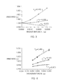
- the speed ratio, ⁇ i.e., the speed of the moving planar element, divided by the peripheral or tangential speed of the undistorted roller far away from the nip, is calculated as a function of engagement for three different assumed values of ⁇ 2 , the Poisson's ratio of the inner, conformable layer.
- the drag force applied to the rigid planar element is zero, the Young's moduli E 1 and E 2 of the compliant blanket and conformable layer are both equal to 0.5 kilopounds per square inch (ksi), or 3.45 MPa. Calculated theoretical results after Load Step 4 are shown in FIG. 3.
- differential overdrive which is manifested by fluctuations of engagement caused for example by eccentricity or concentricity variations of the roller, will be minimized for ⁇ 2 ⁇ 0.30, yet still be small in the range 0.200 ⁇ ⁇ 2 ⁇ 0.350.
- the input parameters are the same as for Example 1, except that a drag force is applied to the planar element (positive drag opposes the direction of motion of the planar element, negative drag is in the same direction).
- the drag force can, of course, be equivalently applied to the roller, and can be expressed as a torque per unit length of the roller.
- the results of applying a positive drag torque of 7.26 inch-oz per inch roller length are shown in FIG. 4, where speed ratio, ⁇ is plotted versus engagement, ⁇ .
- the solid points result from ending the calculation at the end of Load Step 3, and the open points after Load Step 4.
- the downward curvature of the plotted lines for small engagements is a hallmark of impending slippage if the engagement becomes too small.
- This Example further explores speed ratio ⁇ as a function of drag torque per unit length of roller for a constant engagement of 0.0030". All other parameters are the same as for Examples 1 and 2.
- FIG. 5 shows the effects of both positive and negative drag. It can be seen that the sensitivity to drag, i.e., the slopes of the plotted lines, is virtually independent of ⁇ 2 . Moreover, when ⁇ 2 is somewhat above 0.200 and less than 0.350, and preferably less than about 0.3, the amounts of overdrive or underdrive are minimized.
- FIG. 6 The effect of changing the stiffness, i.e., Young's modulus E 2 of the inner, conformable layer is illustrated in FIG. 6, where speed ratio, ⁇ , is plotted versus engagement, ⁇ .
- the results are shown following Load Step 4. Softening the conformable layer has a drastic effect. Underdrive is now observed for all the data points. The upper curve of FIG.
- Poisson's ratio for the inner, conformable layer is preferably in a range between 0.2 and 0.4, and more preferably between 0.20 and 0.35.
- the engagement is preferably less than about 15% to 20% of the thickness of the inner, conformable layer.
- roller 50 includes a tubular rigid cylindrical core member 51, and an elastically deformable structure 52 adhered to the core.
- the elastically deformable structure 52 has an effective or operational Poisson's ratio between 0.2 and 0.4, preferably between 0.25 and 0.35, and more preferably between 0.28 and 0.32.
- the deformable structure 52 includes a thin hard flexible outer layer 53.
- Core member 51 preferably includes a metal such as, for example, aluminum or other suitable metal, and can include internal strengthening members such as struts and the like.
- the hard outer layer 53 has the same dimensions and properties as disclosed above for layer 14 of FIG. 2 (a).
- the elastically deformable structure 52 can include one or more layers.
- the thickness of structure 52 is not critical, and is typically between 2 mm and 15 mm thick.
- the operational or effective Young's modulus is typically in a range 0.5 MPa to 50 MPa, preferably 1 MPa to 10 MPa.
- the elastically deformable structure 52 can further include one or more of the following: a stiffening layer, a particulate filler, an antistat, a composite material, or a polyphase material including a foam.
- the roller 50 can also include a replaceable removable sleeve member.
- the sleeve member includes a supporting or strengthening band (not shown) which is in intimate nonadhesive contact and snugly surrounds core member 51, with the conformable layer uniformly adhered to the strengthening band.
- the other layers 52 and 53 of the roller are as described above.
- the sleeve can be mounted on, or removed from, the core 51 by means of the compressed air technique.
- the sleeve can also be mounted or removed by cooling the core member to shrink it (or warming the sleeve to expand it) and sliding the sleeve along the core member.
- the strengthening band can be rigid, but is preferred to be flexible.
- the strengthening band preferably has a Young's modulus in a range of 100 - 300 GPa, and a thickness preferably in a range of 20 micrometers - 500 micrometers, more preferably 40 micrometers - 100 micrometers.
- the strengthening band which can be fabricated from a sheet, for example by ultrasonic welding or by an adhesive, can be included of any suitable material, including metal, elastomer, plastic or a reinforced material such as, for example, a reinforced silicone belt. It is preferred that the strengthening band be in the form of a seamless web or tube having nickel or steel.
- an indicia on an outer surface near an end of roller 50, e.g., on the outer surface of the elastically deformable structure 52.
- the placement of the indicia and its properties and methods of detection are entirely similar to those of roller 90 described above.
- the invention provides apparatus and methods of reducing both overdrive and differential overdrive associated with an intermediate transfer member roller of an electrostatographic color reproduction machine.
- the primary benefits include an improved registration of color separation toner images, and an improved fidelity of reproduction with minimal distortion of an original or input image to be reproduced.
Landscapes
- Physics & Mathematics (AREA)
- General Physics & Mathematics (AREA)
- Electrostatic Charge, Transfer And Separation In Electrography (AREA)
- Rolls And Other Rotary Bodies (AREA)
Abstract
Description
- FIG. 1(a)
- is a schematic side view, not to scale, of a four-module electrophotographic color reproduction apparatus utilizing intermediate transfer members of the invention in conjunction with a transport belt for receiver members;
- FIG. 1(b)
- is a schematic side view, not to scale, of a four-module electrophotographic color reproduction apparatus utilizing intermediate transfer members of the invention and a common backing drum member for transfer of toner images to receivers;
- FIG. 1(c)
- is a schematic side view, not to scale, of an electrophotographic four-module color reproduction apparatus in which each module uses a common intermediate transfer member of the invention to serially receive color separation toner images for subsequent simultaneous transfer to a receiver;
- FIG. 2 (a)
- is a schematic cross sectional view, not to scale, of a first embodiment of an inventive roller having a conformable layer surrounded by a compliant blanket layer;
- FIG. 2 (b)
- is a schematic cross sectional view, not to scale, of a second embodiment of an inventive roller having a conformable layer surrounded by a stiffening layer, the stiffening layer having formed on it a compliant blanket layer;
- FIG. 3
- shows computed plots of speed ratio as a function of engagement, with zero drag, for different values of Poisson's ratio of the conformable layer of a roller according to the invention, the roller having a conformable layer covered by a compliant blanket layer;
- FIG. 4
- shows computed plots of speed ratio as a function of engagement, with a nominal positive drag torque, for different values of Poisson's ratio of the conformable layer of a roller according to the invention, the roller having a conformable layer covered by a compliant blanket layer;
- FIG. 5
- shows computed plots of speed ratio as a function of drag torque, with a nominal engagement, for different values of Poisson's ratio of the conformable layer of a roller according to the invention, the roller having a conformable layer covered by a compliant blanket layer;
- FIG. 6
- shows computed plots of speed ratio as a function of engagement, with zero drag, for different values of Poisson's ratio of the conformable layer of a roller according to the invention, the roller having a conformable layer covered by a compliant blanket layer, when the Young's modulus of the conformable layer is one-tenth as large as the modulus of the compliant layer;
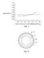
- FIG. 7
- shows a computed plot of speed ratio as a function of Poisson's ratio of the conformable layer of a roller according to the invention, the roller having a conformable layer covered by a compliant blanket layer;
- FIG. 8
- is a schematic cross sectional view, not to scale, of a third embodiment of an inventive ITM roller having an operational or effective Poisson's ratio between 0.2 and 0.4; and
- FIG. 9
- is a sketch of the outside of an inventive ITM roller having marked on its outer surface a descriptive indicia located in a small area located close to an end of the roller.
- ¶1A.
- An intermediate transfer roller for use in electrostatography including:
- a rigid cylindrical core member;
- a conformable layer surrounding the core member;
- an optional thin flexible electrically conductive electrode layer adhered to the conformable layer;
- a compliant blanket layer surrounding and adhered to the electrode layer;
- a thin hard outer layer formed on the compliant blanket layer;
- ¶1B.
- An intermediate transfer roller for use in electrostatography including:
- a rigid cylindrical core member;
- a conformable layer surrounding the core member;
- a stiffening layer surrounding and in intimate contact with the conformable layer;
- a compliant blanket layer formed on the stiffening layer;
- a thin hard outer layer formed on the compliant blanket layer;
- ¶2A.
- The roller according to Paragraph 1A wherein Poisson's ratio of the conformable layer has a value between 0.20 and 0.35.
- ¶2B.
- The roller according to Paragraph 1B wherein Poisson's ratio of the conformable layer has a value between 0.20 and 0.35.
- ¶3A.
- The roller according to Paragraph 1A wherein the conformable layer includes a foam having a solid phase in the form of an open-cell or closed-cell structure.
- ¶3B.
- The roller according to Paragraph 1B wherein the conformable layer includes a foam having a solid phase in the form of an open-cell or closed-cell structure.
- ¶4A.
- The roller according to Paragraph 1A wherein the Poisson's ratio of the compliant blanket layer has a value between 0.4 and 0.5.
- ¶4B.
- The roller according to Paragraph 1B wherein the Poisson's ratio of the compliant blanket layer has a value between 0.4 and 0.5.
- ¶5A.
- The roller according to Paragraph 4A wherein the Poisson's ratio of the compliant blanket layer has a value between 0.45 and 0.50.
- ¶5B.
- The roller according to Paragraph 4B wherein the Poisson's ratio of the compliant blanket layer has a value between 0.45 and 0.50.
- ¶5C.
- The roller according to Paragraph 5A wherein the compliant blanket layer is substantially incompressible and has a Poisson's ratio between 0.48 and 0.50.
- ¶5D.
- The roller according to Paragraph 5C wherein the compliant blanket layer is substantially incompressible and has a Poisson's ratio between 0.48 and 0.50.
- ¶6A.
- The roller according to Paragraph 1A wherein the conformable layer is adhered to the core member.
- ¶6B.
- The roller according to Paragraph 1B wherein the conformable layer is adhered to the core member.
- ¶7A.
- The roller according to Paragraph 1A wherein:
- the conformable layer is adhered to a seamless tubular strengthening band which is in intimate nonadhesive contact with the core member; and
- the strengthening band, the conformable layer, the optional electrode layer, the compliant blanket layer and the thin hard outer layer together create a seamless multilayer tubular replaceable removable sleeve member.
- ¶7B.
- The roller according to Paragraph 1B wherein:
- the conformable layer is adhered to a seamless tubular strengthening band which is in intimate nonadhesive contact with the core member; and
- the strengthening band, the conformable layer, the stiffening layer, the compliant blanket layer and the thin hard outer layer together create a seamless multilayer tubular replaceable removable sleeve member.
- ¶8A.
- The roller according to Paragraph 1A wherein the Young's modulus of the compliant blanket layer is in a range of 0.5 MPa to 50 MPa.
- ¶8B.
- The roller according to Paragraph 1B wherein the Young's modulus of the compliant blanket layer is in a range of 0.5 MPa to 50 MPa.
- ¶9A.
- The roller according to Paragraph 8A wherein the Young's modulus of the compliant blanket layer is in a range of 1 MPa to 10 MPa.
- ¶9B.
- The roller according to Paragraph 8B wherein the Young's modulus of the compliant blanket layer is in a range of 1 MPa to 10 MPa.
- ¶10A.
- The roller according to Paragraph 1A wherein the thickness of the compliant blanket layer is in a range of 0.5 mm to 5 mm.
- ¶10B.
- The roller according to Paragraph 1B wherein the thickness of the compliant blanket layer is in a range of 0.5 mm to 5 mm.
- ¶11A.
- The roller according to Paragraph 10A wherein the thickness of the compliant blanket layer is in a range of 1 mm to 2 mm.
- ¶11B.
- The roller according to Paragraph 10B wherein the thickness of the compliant blanket layer is in a range of 1 mm to 2 mm.
- ¶12A.
- The roller according to Paragraph 1A wherein the electrical resistivity of the compliant blanket layer is in a range of 107 ohm-cm to 1011 ohm-cm.
- ¶12B.
- The roller according to Paragraph 1B wherein the electrical resistivity of the compliant blanket layer is in a range of 107 ohm-cm to 1011 ohm-cm.
- ¶13A.
- The roller according to Paragraph 12A wherein the electrical resistivity of the compliant blanket layer is in a range of 108 ohm-cm to 109 ohm-cm.
- ¶13B.
- The roller according to Paragraph 12B wherein the electrical resistivity of the compliant blanket layer is in a range of 108 ohm-cm to 109 ohm-cm.
- ¶14A.
- The roller according to Paragraph 3A wherein the foam is a felted foam.
- ¶14B.
- The roller according to Paragraph 3B wherein the foam is a felted foam.
- ¶15A.
- The roller according to Paragraph 3A wherein the solid phase of the foam has a Young's modulus in a range of 1 x 10⁶ Pa to 2 x 10⁹ Pa.
- ¶15B.
- The roller according to Paragraph 3B wherein the solid phase of the foam has a Young's modulus in a range of 1 x 10⁶ Pa to 2 x 10⁹ Pa.
- ¶16A.
- The roller according to Paragraph 15A wherein the solid phase of the foam has a Young's modulus in a range of 2 x 10⁶ Pa to 5 x 10⁸ Pa.
- ¶16B.
- The roller according to Paragraph 15B wherein the solid phase of the foam has a Young's modulus in a range of 2 x 10⁶ Pa to 5 x 10⁸ Pa.
- ¶17A.
- The roller according to Paragraph 1A wherein the electrical resistivity of the conformable layer is less than 108 ohm-cm.
- ¶17B.
- The roller according to Paragraph 1B wherein the electrical resistivity of the conformable layer is less than 108 ohm-cm.
- ¶18A.
- The roller according to Paragraph 17A wherein the electrical resistivity of the conformable layer is less than 107 ohm-cm.
- ¶18B.
- The roller according to Paragraph 17B wherein the electrical resistivity of the conformable layer is less than 107 ohm-cm.
- ¶19A.
- The roller according to Paragraph 1A wherein the electrical resistivity of the conformable layer is less than the electrical resistivity of the compliant blanket layer.
- ¶19B.
- The roller according to Paragraph 1B wherein the electrical resistivity of the conformable layer is less than the electrical resistivity of the compliant blanket layer.
- ¶20A.
- The roller according to Paragraph 1A wherein the thickness of the conformable layer is between 3 mm and 25 mm.
- ¶20B.
- The roller according to Paragraph 1B wherein the thickness of the conformable layer is between 3 mm and 25 mm.
- ¶21A.
- The roller according to Paragraph 20A wherein the thickness of the conformable layer is between 5 mm and 10 mm.
- ¶21B.
- The roller according to Paragraph 20B wherein the thickness of the conformable layer is between 5 mm and 10 mm.
- ¶22A.
- The roller according to Paragraph 1A wherein the optional electrode layer is connected to a source of current or voltage.
- ¶22B.
- The roller according to Paragraph 1B wherein the stiffening layer is connected to a source of current or voltage.
- ¶23A.
- The roller according to Paragraph 1A wherein the thin hard outer layer has a Young's modulus greater than 50 MPa, a thickness between 0.1 micrometer and 20 micrometers, and a resistivity at least as high as the resistivity of the compliant blanket layer.
- ¶23B.
- The roller according to Paragraph 1B wherein the thin hard outer layer has a Young's modulus greater than 50 MPa, a thickness between 0.1 micrometer and 20 micrometers, and a resistivity at least as high as the resistivity of the compliant blanket layer.
- ¶24A.
- The roller according to Paragraph 1A wherein the Young's modulus of the conformable layer is of the same order of magnitude as the Young's modulus of the compliant blanket layer.
- ¶24B.
- The roller according to Paragraph 1B wherein the Young's modulus of the conformable layer is of the same order of magnitude as the Young's modulus of the compliant blanket layer.
- ¶25.
- An intermediate transfer roller for use in electrostatography including:
- a rigid cylindrical core member;
- an elastically deformable structure including one or more layers surrounding the core member;
- ¶26.
- A roller according to
Paragraph 25 wherein the said an elastically deformable structure has an operational or effective Poisson's ratio in a range of 0.25 to 0.35. - ¶27.
- The roller according to
Paragraph 26 wherein said an elastically deformable structure has an operational or effective Poisson's ratio in a range of 0.28 to 0.32. - ¶28A.
- A roller according to
Paragraph 25 wherein:- the said an elastically deformable structure is adhered to a seamless tubular strengthening band which is in intimate nonadhesive contact with the core member; and
- the strengthening band and the said an elastically deformable together form a seamless multilayer tubular replaceable removable sleeve member.
- ¶28B.
- A roller according to Paragraph 28A wherein the said elastically deformable structure includes a thin hard layer formed on the elastically deformable structure.
- ¶29A.
- The roller according to Paragraph 1A wherein the thin hard outer layer has a Young's modulus greater than 50 MPa.
- ¶29B.
- The roller according to Paragraph 1B wherein the thin hard outer layer has a Young's modulus greater than 50 MPa.
- ¶29C.
- The roller according to Paragraph 28B wherein the thin hard outer layer has a Young's modulus greater than 50 MPa.
- ¶30A.
- The roller according to Paragraph 29A wherein the thin hard outer layer has a Young's modulus greater than 100 MPa.
- ¶30B.
- The roller according to Paragraph 29B wherein the thin hard outer layer has a Young's modulus greater than 100 MPa.
- ¶30C.
- The roller according to Paragraph 29C wherein the thin hard outer layer has a Young's modulus greater than 100 MPa.
- ¶31A.
- The roller according to Paragraph 1A wherein the thin hard outer layer has a thickness between 0.1 micrometer and 20 micrometers.
- ¶31B.
- The roller according to Paragraph 1B wherein the thin hard outer layer has a thickness between 0.1 micrometer and 20 micrometers.
- ¶31C.
- The roller according to Paragraph 28B wherein the thin hard outer layer has a thickness between 0.1 micrometer and 20 micrometers.
- ¶32A.
- The roller according to Paragraph 7A wherein the strengthening band includes nickel or steel.
- ¶32B.
- The roller according to Paragraph 7B wherein the strengthening band includes nickel or steel.
- ¶32C.
- The roller according to Paragraph 28A wherein the strengthening band includes nickel or steel.
- ¶33A.
- A reproduction method including:
- providing one or more electrostatographic modules, each module including a rotating primary image forming member (PIFM) drum or roller;
- (ITM) drum or roller including: a rigid cylindrical core member, a conformable layer surrounding the core member, an optional thin flexible electrically conductive electrode layer adhered to the conformable layer, a compliant blanket layer surrounding and adhered to the electrode layer, and a thin hard outer layer coated on the blanket layer, wherein the Poisson's ratio of the conformable layer has a value less than or equal to 0.4;
- forming a first pressure transfer nip between each said a rotating primary image forming member and each said a counter-rotating intermediate transfer member;
- forming a single color toner image on each primary image forming member;
- providing an electric transfer field in the nip between each primary image forming member and the respective counter-rotating intermediate transfer member;
- transferring electrostatically each said a single color toner image from each primary image forming member to the respective intermediate transfer member;
- providing a moving web that has or supports a toner image receiving surface;
- providing in each module a respective transfer roller that rotates in the same direction as each said a rotating primary image forming member;
- in each module nipping the moving web between each said an intermediate transfer member and each said a respective transfer roller to form a respective second transfer nip, the web moving parallel to the tangential direction of the transfer roller in the respective second transfer nip;
- providing an electric transfer field in the nip between each intermediate transfer member and each respective transfer roller;
- in each respective second transfer nip, electrostatically transferring from each respective ITM to the receiving surface each said a single color toner image, so that each single color toner image is deposited on the receiving surface in registration so as to form a composite image with the single color toner images previously transferred to the receiving surface by the ITMs of each preceding module.
- ¶33B.
- A reproduction method according to Paragraph 33A wherein the Poisson's ratio of the conformable layer has a value between 0.20 and 0.35.
- ¶34A.
- A reproduction method including:
- providing one or more electrostatographic modules, each module including a rotating primary image forming member (PIFM) drum or roller;
- providing in each module a counter-rotating intermediate transfer member (ITM) drum or roller including: a rigid cylindrical core member, an elastically deformable structure including one or more layers surrounding the core member, wherein the said an elastically deformable structure has an operational or effective Poisson's ratio in a range of 0.2 to 0.4.
- forming a first pressure transfer nip between each said a rotating primary image forming member and each said a counter-rotating intermediate transfer member;
- forming a single color toner image on each primary image forming member;
- providing an electric transfer field in the nip between each primary image forming member and the respective counter-rotating intermediate transfer member;
- transferring electrostatically each said a single color toner image from each primary image forming member to the respective intermediate transfer member;
- providing a moving web including a dielectric material that has or supports a toner image receiving surface;
- providing in each module a respective transfer roller that rotates in the same direction as each said a rotating primary image forming member;
- in each module nipping the moving web between each said an intermediate transfer member and each said a respective transfer roller to form a respective second transfer nip, the web moving parallel to the tangential direction of the transfer roller in the respective second transfer nip;
- providing an electric transfer field in the nip between each intermediate transfer member and each respective transfer roller;
- in each respective second transfer nip, electrostatically transferring from each respective ITM to the receiving surface each said a single color toner image, so that each single color toner image is deposited on the receiving surface in registration so as to form a composite image with the single color toner images previously transferred to the receiving surface by the ITMs of each preceding module.
- ¶34B.
- A reproduction method according to Paragraph 34A wherein the operational or effective Poisson's ratio of the elastically deformable structure has a value between 0.25 and 0.35.
- ¶34B.
- A reproduction method according to Paragraph 34B wherein the operational or effective Poisson's ratio of the elastically deformable structure has a value between 0.28 and 0.32.
- ¶35.
- The roller according to Paragraph 1 B wherein the stiffening layer has a thickness less than 500 micrometers.
- ¶36.
- The roller according to
Paragraph 35 wherein the stiffening layer has a thickness in a range of 10- 200 micrometers. - ¶37.
- The roller according to Paragraph 1B wherein the stiffening layer has a Young's modulus greater than 0.1 GPa.
- ¶38.
- The roller according to Paragraph 37 wherein the stiffening layer has a Young's modulus in a range of 50 - 300 GPa.
Claims (10)
- An intermediate transfer roller for use in electrostatography comprising:a rigid cylindrical core member; andat least one layer of an elastically deformable structure surrounding the core member, said elastically deformable structure having an effective Poisson's ratio in a range of 0.2 to 0.4.
- The transfer roller of claim 1 wherein the effective Poisson's ratio is determined during operation.
- The transfer roller of claim 1 wherein the elastically deformable structure surrounding the core member further comprises:a conformable layer surrounding the core member;a compliant blanket layer surrounding and adhered to the conformable layer;a thin hard outer layer formed on the compliant blanket layer; andwherein Poisson's ratio of the conformable layer has a value less than 0.4.
- An intermediate transfer roller as defined by claim 3 further comprising an electrically conductive layer between the conformable layer and the compliant blanket layer.
- The roller of claim 3 further comprising a stiffening layer surrounding and in intimate contact with the conformable layer.
- The roller according to Claim 1 further comprising:an indicia located on an outer surface of the roller; andwherein the indicia are provided on the roller to indicate a parameter relative to the roller that can be read, sensed or detected by an indicia detector, either visually, electrically, mechanically, optically, magnetically, or by means of a radio frequency.
- An intermediate transfer roller as defined by claim 4 wherein the conformable layer further comprises a foam in which the solid phase has a Young's modulus in a range of 1 x 10⁶ Pa to 2 x 10⁹ Pa, and the conformable layer further having a Poisson's ratio less than 0.4 and a thickness between 3 mm and 25 mm; the compliant blanket layer has a Poisson's ratio between 0.45 and 0.50, a thickness in a range of 0.5 mm to 5 mm, an electrical resistivity in a range 107 ohm-cm to 1011 ohm-cm, and a Young's modulus in a range of 0.5 MPa to 50 MPa; and, the thin hard outer layer has a Young's modulus greater than 50 MPa, a thickness between 0.1 micrometer and 20 micrometers, and a resistivity at least as high as the resistivity of the compliant blanket layer.
- The roller according to claim 4 further comprising a stiffening layer surrounding the conformable layer wherein the stiffening layer has a thickness less than 500 micrometers and a Young's modulus greater than 0.1 Gpa.
- A method of forming an intermediate transfer roller for use in electrostatography comprising the steps of providing a rigid cylindrical core member with at least one layer of an elastically deformable structure surrounding the core member, said elastically deformable structure having an effective Poisson's ratio in a range of 0.2 to 0.4.
- The method of claim 9 wherein the step of providing further comprises providing the elastically deformable structure surrounding the core member such that the conformable layer has a compliant blanket layer surrounding and adhered to the conformable layer, with a thin hard outer layer formed on the compliant blanket layer; and wherein Poisson's ratio of the conformable layer has a value less than 0.4.
Applications Claiming Priority (2)
| Application Number | Priority Date | Filing Date | Title |
|---|---|---|---|
| US09/680,136 US6456816B1 (en) | 2000-10-04 | 2000-10-04 | Method and apparatus for an intermediate image transfer member |
| US680136 | 2000-10-04 |
Publications (3)
| Publication Number | Publication Date |
|---|---|
| EP1195655A2 true EP1195655A2 (en) | 2002-04-10 |
| EP1195655A3 EP1195655A3 (en) | 2005-06-15 |
| EP1195655B1 EP1195655B1 (en) | 2010-03-17 |
Family
ID=24729819
Family Applications (1)
| Application Number | Title | Priority Date | Filing Date |
|---|---|---|---|
| EP01122614A Expired - Lifetime EP1195655B1 (en) | 2000-10-04 | 2001-09-27 | Intermediate transfer member |
Country Status (4)
| Country | Link |
|---|---|
| US (1) | US6456816B1 (en) |
| EP (1) | EP1195655B1 (en) |
| JP (1) | JP2002116634A (en) |
| DE (1) | DE60141559D1 (en) |
Cited By (2)
| Publication number | Priority date | Publication date | Assignee | Title |
|---|---|---|---|---|
| WO2013067422A1 (en) * | 2011-11-02 | 2013-05-10 | E. I. Du Pont De Nemours And Company | A method and an apparatus having a compressible collar for thermally treating a photosensitive precursor |
| DE102015104519A1 (en) * | 2015-03-25 | 2016-09-29 | Océ Printing Systems GmbH & Co. KG | Roller with two elastic layers for transferring a printed image |
Families Citing this family (16)
| Publication number | Priority date | Publication date | Assignee | Title |
|---|---|---|---|---|
| US20050032617A1 (en) * | 2000-04-13 | 2005-02-10 | Hokushin Corporation | Roller member |
| US6745695B2 (en) * | 2000-05-17 | 2004-06-08 | Nexpress Solutions Llc | Printing machine with friction driven image cylinder |
| US6597886B1 (en) * | 2002-01-16 | 2003-07-22 | Kabushiki Kaisha Toshiba | Image forming apparatus |
| US6582222B1 (en) * | 2002-05-06 | 2003-06-24 | Nexpress Solutions Llc | Fusing station including multilayer fuser roller |
| US6967669B2 (en) * | 2003-03-20 | 2005-11-22 | Lexmark International, Inc. | Accumulator drum and method of use for an image forming apparatus |
| US7070406B2 (en) * | 2003-04-29 | 2006-07-04 | Hewlett-Packard Development Company, L.P. | Apparatus for embossing a flexible substrate with a pattern carried by an optically transparent compliant media |
| US7274902B2 (en) * | 2005-03-30 | 2007-09-25 | Hewlett-Packard Development Company, L.P. | Printer transfer member |
| US20090162120A1 (en) * | 2007-12-21 | 2009-06-25 | Manico Joseph A | Printer and printing method using receiver medium having adjustable properties |
| US7875314B2 (en) * | 2007-12-21 | 2011-01-25 | Eastman Kodak Company | Method for using receiver medium having adjustable properties |
| KR101437179B1 (en) * | 2008-09-03 | 2014-09-03 | 코오롱인더스트리 주식회사 | Seamless Belt |
| US8706012B2 (en) * | 2011-07-07 | 2014-04-22 | Eastman Kodak Company | Annular intermediate transfer members, apparatus, and use |
| US9296170B2 (en) * | 2012-10-31 | 2016-03-29 | Eastman Kodak Company | Three-dimensional-structure former |
| JP7639543B2 (en) * | 2021-05-19 | 2025-03-05 | 富士フイルムビジネスイノベーション株式会社 | Conductive roll, transfer device, process cartridge, and image forming apparatus |
| JP7600904B2 (en) * | 2021-06-30 | 2024-12-17 | 富士フイルムビジネスイノベーション株式会社 | Conductive roll, transfer device, process cartridge, and image forming apparatus |
| JP7600905B2 (en) * | 2021-06-30 | 2024-12-17 | 富士フイルムビジネスイノベーション株式会社 | Conductive roll, transfer device, process cartridge and image forming apparatus |
| US11886133B2 (en) * | 2021-12-15 | 2024-01-30 | Xerox Corporation | Printing device with cylindrical intermediate transfer member |
Family Cites Families (55)
| Publication number | Priority date | Publication date | Assignee | Title |
|---|---|---|---|---|
| US3854975A (en) * | 1971-06-30 | 1974-12-17 | Addressograph Multigraph | Pressure fixing of toners |
| US3983287A (en) | 1971-11-22 | 1976-09-28 | Minnesota Mining And Manufacturing Company | Compressible printing blanket |
| GB1429518A (en) | 1973-09-07 | 1976-03-24 | Xerox Corp | Resilient rollers |
| US3863603A (en) | 1974-01-07 | 1975-02-04 | Ibm | Magnetic brush roll having resilient polymeric surface |
| US3959574A (en) | 1974-04-26 | 1976-05-25 | Xerox Corporation | Biasable member and method for making |
| US4378622A (en) | 1977-11-10 | 1983-04-05 | Dayco Corporation | Method of making compressible printing roller |
| US4255508A (en) | 1977-12-27 | 1981-03-10 | Coulter Systems Corporation | Flexible metal printing cylinder having a coating of crystalline photoconductive material |
| US4894687A (en) * | 1980-08-21 | 1990-01-16 | Dennison Manufacturing Company | Pressure transfixing of toner images using skewed rollers |
| US4531825A (en) | 1981-11-25 | 1985-07-30 | Konishiroku Photo Industry Co., Ltd. | Electrostatic reproducing apparatus having an intermediate toner image transfer member |
| US4601963A (en) | 1983-04-15 | 1986-07-22 | Ricoh Company, Ltd. | Locally deformable photosensitive drum for use in electrophotography |
| US4791275A (en) | 1986-04-07 | 1988-12-13 | Imi-Tech Corporation | High temperature compliant roll particularly adapted for xerography |
| JP2672528B2 (en) | 1987-10-20 | 1997-11-05 | 株式会社東芝 | Transfer device |
| US4899197A (en) | 1988-05-17 | 1990-02-06 | Colorocs Corporation | Fuser for use in an electrophotographic print engine |
| US5636349A (en) | 1988-09-08 | 1997-06-03 | Indigo N.V. | Method and apparatus for imaging using an intermediate transfer member |
| US5335054A (en) | 1989-02-06 | 1994-08-02 | Spectrum Sciences B.V. | Image transfer apparatus including intermediate transfer blanket |
| US5592269A (en) | 1993-03-26 | 1997-01-07 | Indigo N.V. | Imaging system having an intermediate transfer member |
| IL111846A0 (en) | 1994-12-01 | 1995-03-15 | Indigo Nv | Imaging apparatus and intermediate transfer blanket therefor |
| DE3921037A1 (en) | 1989-06-27 | 1991-01-10 | Wifag Maschf | METHOD AND DEVICE FOR APPLYING A SOFT-ELASTIC LAYER ON ROLLS FOR GRAPHIC MACHINES |
| US5553541A (en) | 1989-10-05 | 1996-09-10 | Heidelberg Harris Inc | Gapless tubular printing blanket |
| JPH0717114B2 (en) | 1989-10-19 | 1995-03-01 | 住友ゴム工業株式会社 | Offset blanket |
| US5110702A (en) * | 1989-12-11 | 1992-05-05 | Eastman Kodak Company | Process for toned image transfer using a roller |
| EP0517700B1 (en) | 1990-02-26 | 1994-07-13 | Siemens Nixdorf Informationssysteme Aktiengesellschaft | Modular electrophotographic printer |
| US5227853A (en) | 1991-10-16 | 1993-07-13 | Xerox Corporation | Compliant fusing roller |
| JPH05116390A (en) * | 1991-10-24 | 1993-05-14 | Ricoh Co Ltd | Platen roller of thermal transfer recording device |
| US5438398A (en) | 1992-05-29 | 1995-08-01 | Canon Kabushiki Kaisha | Image forming apparatus with intermediate transfer member |
| JPH0611977A (en) * | 1992-06-27 | 1994-01-21 | Ricoh Co Ltd | Image forming device |
| JPH0667551A (en) * | 1992-08-17 | 1994-03-11 | Ricoh Co Ltd | Image forming device |
| US5415961A (en) | 1992-09-29 | 1995-05-16 | Xerox Corporation | Flexible belt supported on rigid drum for electrophotographic imaging |
| US5298956A (en) | 1992-10-07 | 1994-03-29 | Xerox Corporation | Reinforced seamless intermediate transfer member |
| US5386273A (en) | 1993-02-05 | 1995-01-31 | Xerox Corporation | Belt photoreceptor on cylindrical mandrel |
| US5376999A (en) | 1993-06-08 | 1994-12-27 | Xerox Corporation | Device for minimizing intermediate belt stretch and shrinkage in xerographic copier |
| JPH0777879A (en) | 1993-09-07 | 1995-03-20 | Canon Inc | Image forming device |
| JP3086370B2 (en) * | 1993-12-17 | 2000-09-11 | キヤノン株式会社 | Color image forming equipment |
| US5418600A (en) | 1993-12-17 | 1995-05-23 | Xerox Corporation | Conformable friction drive system for belt or drum transport |
| JPH0869233A (en) | 1994-08-26 | 1996-03-12 | Xerox Corp | Assembly of xerographic image formation member |
| JPH0869210A (en) | 1994-08-26 | 1996-03-12 | Xerox Corp | Xerographic-image formation apparatus |
| JP3287136B2 (en) | 1994-10-14 | 2002-05-27 | 富士ゼロックス株式会社 | Image forming device |
| US5508789A (en) | 1994-11-22 | 1996-04-16 | Xerox Corporation | Apparatus and method to control and calibrate deliberate speed mismatch in color IOTs |
| JPH08234600A (en) * | 1995-02-23 | 1996-09-13 | Canon Inc | Heating device and image forming device |
| US5704291A (en) | 1996-01-30 | 1998-01-06 | Presstek, Inc. | Lithographic printing members with deformable cushioning layers |
| JPH09230664A (en) | 1996-02-26 | 1997-09-05 | Fuji Xerox Co Ltd | Image forming method and its device |
| US5689787A (en) * | 1996-05-16 | 1997-11-18 | Eastman Kodak Company | Transfer member having sectioned surface coating to enhance micro-compliance |
| JPH1020681A (en) * | 1996-07-03 | 1998-01-23 | Toray Ind Inc | Image forming apparatus and image forming method |
| US6075965A (en) | 1996-07-29 | 2000-06-13 | Eastman Kodak Company | Method and apparatus using an endless web for facilitating transfer of a marking particle image from an intermediate image transfer member to a receiver member |
| JP3378162B2 (en) * | 1997-01-21 | 2003-02-17 | シャープ株式会社 | Image forming apparatus and method for manufacturing dielectric sheet |
| JP3133695B2 (en) | 1997-03-10 | 2001-02-13 | 筒中シート防水株式会社 | Waterproof construction method for irregularly shaped protrusions on flat roofs, etc. |
| JPH10319732A (en) * | 1997-05-22 | 1998-12-04 | Minolta Co Ltd | Electrophotographic intermediate transfer body |
| JPH117205A (en) | 1997-06-17 | 1999-01-12 | Fuji Xerox Co Ltd | Image forming device |
| JP3248455B2 (en) | 1997-07-03 | 2002-01-21 | 富士ゼロックス株式会社 | Image forming apparatus and method of manufacturing intermediate transfer belt used in the same |
| US5894796A (en) | 1997-08-01 | 1999-04-20 | Heidelberger Druckmaschinen Ag | Printing unit for a web-fed rotary printing press |
| US5926679A (en) * | 1997-12-08 | 1999-07-20 | Eastman Kodak Company | Method and apparatus for forming an image for transfer to a receiver sheet using a clear toner and sintering of a pigmented toner layer |
| US5946534A (en) | 1998-01-08 | 1999-08-31 | Xerox Corporation | Apparatus and method for non-interactive electrophotographic development |
| US5982477A (en) * | 1998-05-27 | 1999-11-09 | Eastman Kodak Company | Film drive apparatus for a photographic film scanner |
| JP2000047499A (en) * | 1998-07-31 | 2000-02-18 | Kyocera Corp | Color image forming equipment |
| JP3625407B2 (en) * | 1999-01-14 | 2005-03-02 | キヤノン株式会社 | Image forming apparatus, storage medium, and belt body thickness information updating method |
-
2000
- 2000-10-04 US US09/680,136 patent/US6456816B1/en not_active Expired - Fee Related
-
2001
- 2001-06-07 JP JP2001173015A patent/JP2002116634A/en active Pending
- 2001-09-27 EP EP01122614A patent/EP1195655B1/en not_active Expired - Lifetime
- 2001-09-27 DE DE60141559T patent/DE60141559D1/en not_active Expired - Lifetime
Cited By (5)
| Publication number | Priority date | Publication date | Assignee | Title |
|---|---|---|---|---|
| WO2013067422A1 (en) * | 2011-11-02 | 2013-05-10 | E. I. Du Pont De Nemours And Company | A method and an apparatus having a compressible collar for thermally treating a photosensitive precursor |
| US9032877B2 (en) | 2011-11-02 | 2015-05-19 | E I Du Pont De Nemours And Company | Method and an apparatus having a compressible collar for thermally treating a photosensitive precursor |
| US9291906B2 (en) | 2011-11-02 | 2016-03-22 | E I Du Pont De Nemours And Company | Method and an apparatus having a compressible collar for thermally treating a photosensitive precursor |
| DE102015104519A1 (en) * | 2015-03-25 | 2016-09-29 | Océ Printing Systems GmbH & Co. KG | Roller with two elastic layers for transferring a printed image |
| US9753412B2 (en) | 2015-03-25 | 2017-09-05 | Océ Printing Systems GmbH & Co. KG | Roller having elastic layers for transferring a print image |
Also Published As
| Publication number | Publication date |
|---|---|
| EP1195655B1 (en) | 2010-03-17 |
| EP1195655A3 (en) | 2005-06-15 |
| DE60141559D1 (en) | 2010-04-29 |
| JP2002116634A (en) | 2002-04-19 |
| US6456816B1 (en) | 2002-09-24 |
Similar Documents
| Publication | Publication Date | Title |
|---|---|---|
| EP1195655B1 (en) | Intermediate transfer member | |
| EP1237054B1 (en) | Method and apparatus for controlling overdrive in a frictionally driven system including a conformable member | |
| US6556798B2 (en) | Method and apparatus for using a conformable member in a frictional drive | |
| US6163669A (en) | Image forming apparatus | |
| US6605399B2 (en) | Sleeved Photoconductive member and method of making | |
| US6393226B1 (en) | Intermediate transfer member having a stiffening layer and method of using | |
| JP3039744B2 (en) | Image forming device | |
| JP2002123052A (en) | Image forming apparatus | |
| EP0840175B1 (en) | An image forming apparatus | |
| US6226465B1 (en) | Image forming apparatus with relative speed differential between intermediate transfer member and image bearing member | |
| US12372900B2 (en) | Image forming apparatus | |
| US6393250B1 (en) | Cleaning apparatus and image forming apparatus | |
| JP2003131444A (en) | Image forming apparatus | |
| JPS62134674A (en) | Image recorder | |
| JP3880459B2 (en) | Image forming apparatus | |
| JPH11194578A (en) | Color image forming equipment | |
| US6442357B2 (en) | Transfer apparatus employing a transfer roller having a dielectric layer on its outer surface | |
| JP2003173092A (en) | Image forming device | |
| JP2007101755A (en) | Image forming apparatus | |
| JPH08240959A (en) | Image forming method and device | |
| US6453142B1 (en) | Developing apparatus equipped with developing roller having a dielectric layer outer surface | |
| JPH10171259A (en) | Belt-like transfer body for electrophotographic apparatus and method of manufacturing the same | |
| JP2821179B2 (en) | Developing device | |
| JPH07261568A (en) | Color image forming device | |
| JPH07253716A (en) | Development device |
Legal Events
| Date | Code | Title | Description |
|---|---|---|---|
| PUAI | Public reference made under article 153(3) epc to a published international application that has entered the european phase |
Free format text: ORIGINAL CODE: 0009012 |
|
| AK | Designated contracting states |
Kind code of ref document: A2 Designated state(s): AT BE CH CY DE DK ES FI FR GB GR IE IT LI LU MC NL PT SE TR |
|
| AX | Request for extension of the european patent |
Free format text: AL;LT;LV;MK;RO;SI |
|
| RAP1 | Party data changed (applicant data changed or rights of an application transferred) |
Owner name: EASTMAN KODAK COMPANY |
|
| PUAL | Search report despatched |
Free format text: ORIGINAL CODE: 0009013 |
|
| AK | Designated contracting states |
Kind code of ref document: A3 Designated state(s): AT BE CH CY DE DK ES FI FR GB GR IE IT LI LU MC NL PT SE TR |
|
| AX | Request for extension of the european patent |
Extension state: AL LT LV MK RO SI |
|
| 17P | Request for examination filed |
Effective date: 20051021 |
|
| AKX | Designation fees paid |
Designated state(s): DE FR GB |
|
| 17Q | First examination report despatched |
Effective date: 20080124 |
|
| GRAP | Despatch of communication of intention to grant a patent |
Free format text: ORIGINAL CODE: EPIDOSNIGR1 |
|
| GRAS | Grant fee paid |
Free format text: ORIGINAL CODE: EPIDOSNIGR3 |
|
| GRAA | (expected) grant |
Free format text: ORIGINAL CODE: 0009210 |
|
| AK | Designated contracting states |
Kind code of ref document: B1 Designated state(s): DE FR GB |
|
| REG | Reference to a national code |
Ref country code: GB Ref legal event code: FG4D |
|
| REF | Corresponds to: |
Ref document number: 60141559 Country of ref document: DE Date of ref document: 20100429 Kind code of ref document: P |
|
| PLBE | No opposition filed within time limit |
Free format text: ORIGINAL CODE: 0009261 |
|
| STAA | Information on the status of an ep patent application or granted ep patent |
Free format text: STATUS: NO OPPOSITION FILED WITHIN TIME LIMIT |
|
| 26N | No opposition filed |
Effective date: 20101220 |
|
| REG | Reference to a national code |
Ref country code: FR Ref legal event code: ST Effective date: 20110531 |
|
| PG25 | Lapsed in a contracting state [announced via postgrant information from national office to epo] |
Ref country code: FR Free format text: LAPSE BECAUSE OF NON-PAYMENT OF DUE FEES Effective date: 20100930 |
|
| PGFP | Annual fee paid to national office [announced via postgrant information from national office to epo] |
Ref country code: GB Payment date: 20130827 Year of fee payment: 13 |
|
| PGFP | Annual fee paid to national office [announced via postgrant information from national office to epo] |
Ref country code: DE Payment date: 20130930 Year of fee payment: 13 |
|
| REG | Reference to a national code |
Ref country code: DE Ref legal event code: R119 Ref document number: 60141559 Country of ref document: DE |
|
| GBPC | Gb: european patent ceased through non-payment of renewal fee |
Effective date: 20140927 |
|
| REG | Reference to a national code |
Ref country code: DE Ref legal event code: R119 Ref document number: 60141559 Country of ref document: DE Effective date: 20150401 |
|
| PG25 | Lapsed in a contracting state [announced via postgrant information from national office to epo] |
Ref country code: GB Free format text: LAPSE BECAUSE OF NON-PAYMENT OF DUE FEES Effective date: 20140927 Ref country code: DE Free format text: LAPSE BECAUSE OF NON-PAYMENT OF DUE FEES Effective date: 20150401 |