EP1195553A1 - Oblong headlamp - Google Patents
Oblong headlamp Download PDFInfo
- Publication number
- EP1195553A1 EP1195553A1 EP00120689A EP00120689A EP1195553A1 EP 1195553 A1 EP1195553 A1 EP 1195553A1 EP 00120689 A EP00120689 A EP 00120689A EP 00120689 A EP00120689 A EP 00120689A EP 1195553 A1 EP1195553 A1 EP 1195553A1
- Authority
- EP
- European Patent Office
- Prior art keywords
- reflector
- headlamp
- focal point
- light
- optical axis
- Prior art date
- Legal status (The legal status is an assumption and is not a legal conclusion. Google has not performed a legal analysis and makes no representation as to the accuracy of the status listed.)
- Withdrawn
Links
Images



Classifications
-
- F—MECHANICAL ENGINEERING; LIGHTING; HEATING; WEAPONS; BLASTING
- F21—LIGHTING
- F21S—NON-PORTABLE LIGHTING DEVICES; SYSTEMS THEREOF; VEHICLE LIGHTING DEVICES SPECIALLY ADAPTED FOR VEHICLE EXTERIORS
- F21S41/00—Illuminating devices specially adapted for vehicle exteriors, e.g. headlamps
- F21S41/30—Illuminating devices specially adapted for vehicle exteriors, e.g. headlamps characterised by reflectors
- F21S41/32—Optical layout thereof
- F21S41/36—Combinations of two or more separate reflectors
- F21S41/365—Combinations of two or more separate reflectors successively reflecting the light
-
- F—MECHANICAL ENGINEERING; LIGHTING; HEATING; WEAPONS; BLASTING
- F21—LIGHTING
- F21S—NON-PORTABLE LIGHTING DEVICES; SYSTEMS THEREOF; VEHICLE LIGHTING DEVICES SPECIALLY ADAPTED FOR VEHICLE EXTERIORS
- F21S41/00—Illuminating devices specially adapted for vehicle exteriors, e.g. headlamps
- F21S41/40—Illuminating devices specially adapted for vehicle exteriors, e.g. headlamps characterised by screens, non-reflecting members, light-shielding members or fixed shades
- F21S41/43—Illuminating devices specially adapted for vehicle exteriors, e.g. headlamps characterised by screens, non-reflecting members, light-shielding members or fixed shades characterised by the shape thereof
-
- F—MECHANICAL ENGINEERING; LIGHTING; HEATING; WEAPONS; BLASTING
- F21—LIGHTING
- F21V—FUNCTIONAL FEATURES OR DETAILS OF LIGHTING DEVICES OR SYSTEMS THEREOF; STRUCTURAL COMBINATIONS OF LIGHTING DEVICES WITH OTHER ARTICLES, NOT OTHERWISE PROVIDED FOR
- F21V13/00—Producing particular characteristics or distribution of the light emitted by means of a combination of elements specified in two or more of main groups F21V1/00 - F21V11/00
- F21V13/02—Combinations of only two kinds of elements
- F21V13/10—Combinations of only two kinds of elements the elements being reflectors and screens
Definitions
- the present invention relates to a vehicular headlamp for irradiating light ahead of a vehicle such as a headlight, auxiliary headlight or the like. Specifically, the present invention relates to the constitution of a headlamp having a vertically long shape in a state where it is mounted to a vehicle.
- Fig. 1 shows a constitution example of a conventional headlamp.
- This headlamp 90 is composed of a reflector 91, a light source 92 and a lens 93.
- the reflector 91 is composed of a parabolic reflector such as a revolved parabolic surface, a columnar parabolic surface, a free curved surface and the like and a light source 92 is arranged generally at the position of a focal point thereof.
- the light source 92 is, for example, a C-6 type or C-8 type filament (the figure shows a C-6 type as an example).
- the reflector 91 of the headlamp 90 used in this state provides a projected surface area having a width w in the horizontal direction of 150 - 300 mm and a height h in the vertical direction of 80 - 150 mm.
- the C-6 type light source 92 which is provided orthogonally to the optical axis of the headlamp.
- a C-8 type filament is often used as a light source 92 as a countermeasure because there is provided inside the light bulb a hood for shielding light which is in parallel with the optical axis and reaches generally the lower half part of the reflector 91 (an halogen lamp called H4 and a discharge lamp called HID also have a light source generally in the same shape).
- H4 and a discharge lamp called HID also have a light source generally in the same shape.
- the luminous flux efficiency of the light source 92 inevitably decreases due to the hood.
- the match with the design of a vehicle to which this headlamp 90 is mounted is emphasized in the design of the headlamp 90 such as the aspect ratio of the reflector 91 or the like.
- a so-called vertically long design having a width w smaller than a height h can be required.
- a headlamp 90 of this kind usually requires a luminous intensity distribution property having a width greater in the horizontal direction. If the width w necessary for securing a quantity of light in the horizontal direction is set narrow, the quantity of light substantially decreases including the case where a C-6 type filament is used. Thus, there is caused a problem that the quantity of light obtained is only half of that of a conventional one if the width w is made as narrow as, for example, about 50 mm. Such a headlamp is practically impossible to use.
- a C-8 type filament or H4 or HID
- the hood provided for preventing generation of upward light does not function.
- the luminous intensity distribution property is deteriorated.
- the hood is provided, the quantity of light further decreases. In either case, the requirement of the vertically long design has not been met and thereby there has been a problem that the vehicle design is also restricted.
- an object of the present invention is to provide a vertically long headlamp having a narrow width in the horizontal direction, with which the quantity of light does not decrease and a favorable luminous intensity distribution property can be obtained, so as to solve the above problems.
- the present invention provides a headlamp which is composed of a light source, a first reflector formed of an elliptic reflector having a first focal point at which the light source is arranged, and a second reflector formed of a parabolic reflector having a focal point which is disposed in the vicinity of a second focal point of the first reflector.
- the headlamp also has at least one two-times-reflection optical system in which the first reflector and the second reflector are disposed generally along the vertical direction in a state that the headlamp is mounted.
- the headlamp is characterized in that at least one of the two-times-reflection optical systems is constituted such that the second focal point of the first reflector is shifted from the vertical center line passing the optical axis of the headlamp in the lateral direction and because of this the optical axis passing the focal point of the second reflector is also shifted in the same direction.
- the headlamp of the present invention having the above constitution can be used to achieve a vertically long headlamp capable of securing a sufficient quantity of light by transmitting light to the second reflector from the first reflector, which has an elliptic shape excellent in convergence, even when the vertically long headlamp requires a narrow width in the horizontal direction.
- the vehicle design is not restricted.
- the luminous intensity distribution property of a vertically long headlamp of this kind can be readily obtained by tilting the first reflector.
- a side-face mirror is provided generally perpendicular to the vertical direction and generally in parallel with the optical axis in the front and back direction at least on the side surface of the second reflector on the side towards which the optical axis is shifted.
- a shielding plate for forming a cutoff line in the luminous intensity distribution property in the vicinity of the second focal point of the first reflector as a plate generally in parallel with the major axis of the first reflector and that the surface thereof facing the first reflector is subjected to a reflection treatment to constitute an inner-face mirror.
- the shielding plate may have been bent or curved, by which the luminous intensity distribution property can be controlled.
- the first reflector may be divided to constitute a composite reflector.
- loss in the quantity of light is prevented by providing a side-face mirror. Therefore, a vertically long headlamp of this kind can be readily achieved. Furthermore, a required luminous intensity distribution property can be obtained. Thus, an excellent effect is made on the improvement in performance of the vertically long headlamp of this kind.
- reference numeral 1 denotes a headlamp of a first embodiment according to the present invention.
- This figure shows a cross-sectional view in the vertical direction of this headlamp 1 in a state that it is mounted to a vehicle.
- a light source 2 such as a filament, a discharge lamp arc or the like so that the longitudinal direction thereof is along the horizontal direction and orthogonally to the irradiating direction. That is, the light source 2 provided is of the same form as the C-6 type filament.
- a first reflector 3 constituted by an elliptic reflector such as a spheroid or the like and a second reflector 4 constituted by a parabolic reflector such as a revolved paraboloid or the like above the light source 2 of this headlamp 1.
- a third reflector 5 constituted by an elliptic reflector and a fourth reflector 6 constituted by a parabolic reflector below the light source 2.
- a fifth reflector 7 constituted by a parabolic reflector below and frontward the light source 2.
- the first reflector 3 has a first focal point f31 at the position where the light source 2 is disposed.
- This first reflector 3 images the light source 2 at a second focal point f32 thereof.
- the second reflector 4 has a focal point f4 in the vicinity of the second focal point f32. Therefore, the light reflected by the first reflector 3 is further reflected by the second reflector 4 and emitted in the irradiating direction of the headlamp 1 as a generally parallel light beam.
- the second reflector 4 Since the second reflector 4 is formed such that the most part thereof is above the center line (optical axis) z4 passing the focal point f4, the light reflected from the second reflector 4 is emitted downward and is suitable for the luminous intensity distribution for passing-by if the focal point f4 of the second reflector 4 is appropriately set at the back of the second focal point f32 of the first reflector 3.
- the fifth reflector 7 is formed by a parabolic reflector such as a revolved parabolic surface or the like, where the focal point thereof is positioned generally at the light source 2. Therefore, the fifth reflector 7 captures a part of the light which cannot be captured by the first reflector 3 or the third reflector 5 and reflects it in the irradiating direction as a generally parallel light beam. Consequently, the luminous flux capture rate of the light source 2 is further increased. It is noted that the position of the focal point of this fifth reflector 7 may also be appropriately adjusted so as to obtain a required luminous intensity distribution property as a reflected light which is directed slightly downward.
- the above is the basic constitution of the headlamp 1 according to the present invention.
- This constitution has already been filed by the same applicant as the applicant of Japanese Patent Application No. Hei 11-82052.
- the constitution described below is added to the above constitution so as to readily and precisely provide a luminous intensity distribution property and further improve the luminous flux efficiency of the light source 2.
- a shielding plate 8 for shielding a part of the light which is unnecessary in the formation of a luminous intensity distribution property is provided in the vicinity of the second focal point f32 of the first reflector 3 as seen in a conventional projector-type headlamp.
- this shielding plate 8 is formed generally in parallel with the major axis z3 of the first reflector 3 and in the vicinity of the first reflector 3. At this time, the end surface of the shielding plate 8 on the side closer to the second focal point f32 constitutes a shielding part 8a.
- the surface of the shielding plate 8 facing the first reflector 3 is subjected to an appropriate reflection treatment such as aluminum vapor deposition or the like to form an inner-face mirror part 8b. Therefore, in the constitution of the shielding plate 8 of the present invention, unnecessary light is eliminated by the shielding part 8a and thus generation of dazzling light from a headlamp 1 obtained can be further reduced. Also, the light which is conventionally invalid because it is shielded by the shielding plate upon contact is reflected at the inner-face mirror part 8b and directed to the second reflector 4. Consequently, the brightness of the headlamp 1 is further enhanced. It is noted that, as also shown in Fig. 2, the shielding plate 8 can also be used for the third reflector 5 and that any of the other embodiments described below can be used similarly.
- Fig. 3 shows the second part of the constitution added according to the present invention.
- the figure is a front view of the headlamp 1 seen from the side of the irradiating direction.
- the present invention is characterized in that the major axis z3 including the first focal point f31 and the second focal point f32 of the first reflector 3 is inclined to the right or left of the first focal point f31, which is the center of rotation (the figure shows the leftward inclined state when viewed from the front side). That is, the second focal point f32 of the first reflector 3 is provided off the vertical center line passing the optical axis of the headlamp 1, and because of this the optical axis z4 passing the focal point f4 of the second reflector 4 is also shifted in the same direction.
- Fig. 4 is an illustration of the luminous intensity distribution property showing an action when the aforementioned major axis z3 is inclined.
- the luminous intensity distribution of the irradiated light which is first reflected by the first reflector 3, for which the above-described shielding plate 8 is provided, and then further reflected by the second reflector 4 has a generally heart-shaped pattern when the light is not diffused by a lens 10 (see Fig. 2) or the like.
- the major axis z3 is vertical, the heart-shaped pattern is erected.
- the heart-shaped pattern F is also inclined by inclining the major axis z3. Consequently, no upward light is generated on the opposite lane side (upper right side in the figure) while, at the same time, upward light is secured on the shoulder side (upper left side in the figure) so that road signs or the like can be easily read.
- This basic shape of the luminous intensity distribution property can be obtained only by the first reflector 3 and the second reflector 4. The case of the left-side traffic has been described above. In the case of the right-side traffic, the first reflector 3 can be inclined toward the opposite side.
- Fig. 3 will be described in detail below. If the major axis z3 is inclined when the width w of the headlamp 1 is narrow, the quantity of light is lost because the light directing to the left of the major axis z3 in a state shown in the figure does not have a second reflector 4 on which the light should be made incident.
- the present invention solves this problem as well.
- a side-face mirror 9 on the side surface on the side toward which the optical axis z3 is inclined.
- the side-face mirror 9 is formed such that it is perpendicular to the vertical direction and in parallel with the optical axis z4 of the second reflector 4 in the front and back direction.
- the second focal point f32 of the first reflector 3 coincides with the surface of the side-face mirror 9.
- the surface of the side-face mirror 9 coincides with the second focal point f32 of the first reflector 3
- the light from the right half part of the first reflector 3 becomes equivalent to the light from the left half part. Consequently, the loss of light is not only compensated, but, rather, the brightness of the headlamp 1 is further enhanced due to an action like doubling the area of the second reflector 4.
- Fig. 5 shows a second embodiment of the present invention.
- the above-described embodiment is constituted such that the shielding plate 8 is formed as a plane plate, but the present invention is not limited to this constitution.
- the shielding plate 18 is in a slightly bent shape to obtain an action of positively increasing the quantity of light on the shoulder side as is the shielding plate of a conventional projector-type headlamp.
- a folding line 18c for bending is formed generally in parallel with the major axis z3 of the first reflector 3.
- the end part of the shielding plate 18 which is closer to the second focal point f32 constitutes a shielding part 18a and the surface facing the first reflector 3 constitutes an inner-face reflection mirror 18b.
- a shielding plate 28 formed by a resin injection molding or metal die casting.
- the shielding plate 28 is formed, for example, as a wedge shape having a thickness which increases as the distance from the light source 2 increases and the plane shape is freely formed in a trapezoid or the like so as to give more flexibility in the shape of the shielding part 28a.
- the side surface part 28c adjacent to and continued with the inner-face reflection mirror 28b may also be subjected to a reflection treatment to radiate light to, for example, the first reflector 3, second reflector 4 or side-face mirror 9.
- the shape of a border between light and shade which is the upper end part of the luminous intensity distribution property for passing-by, is freely formed, and thereby the required luminous intensity distribution property can be obtained.
- the shape can also be set more accurately and the performance of a headlamp 1 is further improved.
- Figs. 7, 8 and 9 show still other embodiments of the present invention.
- the luminous intensity distribution property is further improved by modifying the shape of the first reflector.
- the luminous intensity distribution property having an irradiation width which is narrow in the vertical direction and wide in the lateral direction is preferable in all aspects including improvement of the visibility or the like.
- the first reflector 31 is constituted by three segments along the major axis z3 in the present invention.
- the divided right side part 31a and left side part 31c thereof are constituted by a spheroidal reflector having a first focal point f31 and second focal point f32 as focal points as in the first embodiment.
- the central part 31b thereof is constituted by an elliptic columnar surface.
- a luminous flux S generated at the second focal point f32 of the first reflector 31 has a dimension which is narrow in the vertical direction and wide in the lateral direction. This shape is optimal to form a luminous intensity distribution property of a vehicular headlamp.
- the first reflector 32 can be divided into radial segments using the first focal point f31 as the origin and formed as a combination of a plurality of divided spheroids each having a second focal point f32a - f32d on the axis of each divided segment.
- a luminous flux S which is narrow in the vertical direction and wide in the lateral direction can be obtained.
- any of the above embodiments can be employed.
- a free curved surface may be employed to obtain a similar luminous flux S.
- Fig. 10 shows a sixth embodiment of the present invention.
- the side-face mirror 9 is formed as a plane, but the side surface is not limited to a plane in the present invention.
- steps 19a on the side-face mirror 19 may be provided on the side-face mirror 19 as shown in the figure.
- the formation of the luminous intensity distribution property may be positively influenced by providing a direction to the light reaching the second reflector 4 from this side-face mirror 19.
- steps 19a are added but also the side-face mirror itself may be formed as a curved surface although it is not shown in the figure. Further, the surfaces facing the side-face mirrors 9, 19 may also be subjected to a reflection treatment to prepare auxiliary side-face mirrors 9b (see Fig. 3), 19b. In addition, steps may be added to the auxiliary side-face mirrors 9b, 19b.
Landscapes
- Engineering & Computer Science (AREA)
- General Engineering & Computer Science (AREA)
- Non-Portable Lighting Devices Or Systems Thereof (AREA)
Abstract
A headlamp (1) having at least one two-times-reflection optical
system which is composed of a first reflector (3) constituted by an
elliptical reflector where a light source (2) is disposed at a first
focal (f31) point thereof, and a second reflector (4) constituted by a
parabolic reflector where a focal point thereof is disposed in the
vicinity of a second focal point of the first reflector (f32). In at
least one two-times-reflection optical system of this headlamp, the
second focal point (f32) of the first reflector (3) is shifted in the
lateral direction and the optical axis (z3) passing the focal point of
the second reflector (4) is also shifted in the same direction.
Consequently, in the headlamp having a narrow width in the lateral
direction, light is transferred to the second reflector (4) by the first
reflector (3) constituted by an elliptic reflector, which is excellent
in convergence, to provide a sufficient quantity of light and an
excellent luminous intensity distribution property.
Description
- The present invention relates to a vehicular headlamp for irradiating light ahead of a vehicle such as a headlight, auxiliary headlight or the like. Specifically, the present invention relates to the constitution of a headlamp having a vertically long shape in a state where it is mounted to a vehicle.
- Fig. 1 shows a constitution example of a conventional headlamp. This
headlamp 90 is composed of areflector 91, alight source 92 and alens 93. Thereflector 91 is composed of a parabolic reflector such as a revolved parabolic surface, a columnar parabolic surface, a free curved surface and the like and alight source 92 is arranged generally at the position of a focal point thereof. Thelight source 92 is, for example, a C-6 type or C-8 type filament (the figure shows a C-6 type as an example). Thereflector 91 of theheadlamp 90 used in this state provides a projected surface area having a width w in the horizontal direction of 150 - 300 mm and a height h in the vertical direction of 80 - 150 mm. - At this time, upward light is generated on the side of the opposite lane by the C-6
type light source 92, which is provided orthogonally to the optical axis of the headlamp. In recent years, a C-8 type filament is often used as alight source 92 as a countermeasure because there is provided inside the light bulb a hood for shielding light which is in parallel with the optical axis and reaches generally the lower half part of the reflector 91 (an halogen lamp called H4 and a discharge lamp called HID also have a light source generally in the same shape). In this case, however, the luminous flux efficiency of thelight source 92 inevitably decreases due to the hood. - The match with the design of a vehicle to which this
headlamp 90 is mounted is emphasized in the design of theheadlamp 90 such as the aspect ratio of thereflector 91 or the like. For example, a so-called vertically long design having a width w smaller than a height h can be required. - However, a
headlamp 90 of this kind usually requires a luminous intensity distribution property having a width greater in the horizontal direction. If the width w necessary for securing a quantity of light in the horizontal direction is set narrow, the quantity of light substantially decreases including the case where a C-6 type filament is used. Thus, there is caused a problem that the quantity of light obtained is only half of that of a conventional one if the width w is made as narrow as, for example, about 50 mm. Such a headlamp is practically impossible to use. - If a C-8 type filament (or H4 or HID), in particular, is used as a
light source 92, the hood provided for preventing generation of upward light does not function. As a result, the luminous intensity distribution property is deteriorated. Additionally, since the hood is provided, the quantity of light further decreases. In either case, the requirement of the vertically long design has not been met and thereby there has been a problem that the vehicle design is also restricted. - Accordingly, an object of the present invention is to provide a vertically long headlamp having a narrow width in the horizontal direction, with which the quantity of light does not decrease and a favorable luminous intensity distribution property can be obtained, so as to solve the above problems.
- In order to achieve the above object, the present invention provides a headlamp which is composed of a light source, a first reflector formed of an elliptic reflector having a first focal point at which the light source is arranged, and a second reflector formed of a parabolic reflector having a focal point which is disposed in the vicinity of a second focal point of the first reflector. The headlamp also has at least one two-times-reflection optical system in which the first reflector and the second reflector are disposed generally along the vertical direction in a state that the headlamp is mounted. The headlamp is characterized in that at least one of the two-times-reflection optical systems is constituted such that the second focal point of the first reflector is shifted from the vertical center line passing the optical axis of the headlamp in the lateral direction and because of this the optical axis passing the focal point of the second reflector is also shifted in the same direction.
- The headlamp of the present invention having the above constitution can be used to achieve a vertically long headlamp capable of securing a sufficient quantity of light by transmitting light to the second reflector from the first reflector, which has an elliptic shape excellent in convergence, even when the vertically long headlamp requires a narrow width in the horizontal direction. Thus, the vehicle design is not restricted.
- Also, the luminous intensity distribution property of a vertically long headlamp of this kind can be readily obtained by tilting the first reflector.
- In the above constitution, it is preferable that a side-face mirror is provided generally perpendicular to the vertical direction and generally in parallel with the optical axis in the front and back direction at least on the side surface of the second reflector on the side towards which the optical axis is shifted.
- In this headlamp, it is preferable that there is provided a shielding plate for forming a cutoff line in the luminous intensity distribution property in the vicinity of the second focal point of the first reflector as a plate generally in parallel with the major axis of the first reflector and that the surface thereof facing the first reflector is subjected to a reflection treatment to constitute an inner-face mirror.
- At this time, the shielding plate may have been bent or curved, by which the luminous intensity distribution property can be controlled.
- Also, the first reflector may be divided to constitute a composite reflector. According to the constitution of the present invention, loss in the quantity of light is prevented by providing a side-face mirror. Therefore, a vertically long headlamp of this kind can be readily achieved. Furthermore, a required luminous intensity distribution property can be obtained. Thus, an excellent effect is made on the improvement in performance of the vertically long headlamp of this kind.
- These and other objects and advantages of the present invention will become clear from the following description with reference to the accompanying drawings, wherein:
- Fig. 1 is an illustration showing a headlamp according to the prior art;
- Fig. 2 is a cross-sectional view showing a first embodiment of the headlamp according to the present invention;
- Fig. 3 is a front view of the first embodiment;
- Fig. 4 is an illustration of a luminous intensity distribution property showing an action of the first embodiment;
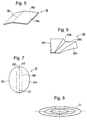
- Fig. 5 is a perspective view showing an essential part of a second embodiment of the headlamp according to the present invention;
- Fig. 6 is a perspective view showing an essential part of a third embodiment of the headlamp according to the present invention;
- Fig. 7 is a plan view showing an essential part of a fourth embodiment of the headlamp according to the present invention;
- Fig. 8 is an illustration of a luminous intensity distribution property showing an action of the fourth embodiment;
- Fig. 9 is a plan view showing an essential part of a fifth embodiment of the headlamp according to the present invention; and
- Fig. 10 is a front view showing an essential part of a sixth embodiment of the headlamp according to the present invention.
-
- The present invention will be described in detail below with reference to the embodiments shown in the drawings. It is noted that terms referring to directions such as front, back, right, left and vertical in the present specification are based on a vehicle to which a headlamp is mounted unless otherwise defined. In Fig. 2,
reference numeral 1 denotes a headlamp of a first embodiment according to the present invention. This figure shows a cross-sectional view in the vertical direction of thisheadlamp 1 in a state that it is mounted to a vehicle. In theheadlamp 1, there is provided alight source 2 such as a filament, a discharge lamp arc or the like so that the longitudinal direction thereof is along the horizontal direction and orthogonally to the irradiating direction. That is, thelight source 2 provided is of the same form as the C-6 type filament. - Additionally, there are provided a
first reflector 3 constituted by an elliptic reflector such as a spheroid or the like and asecond reflector 4 constituted by a parabolic reflector such as a revolved paraboloid or the like above thelight source 2 of thisheadlamp 1. There are provided athird reflector 5 constituted by an elliptic reflector and afourth reflector 6 constituted by a parabolic reflector below thelight source 2. Further, there is provided a fifth reflector 7 constituted by a parabolic reflector below and frontward thelight source 2. - At this time, the
first reflector 3 has a first focal point f31 at the position where thelight source 2 is disposed. Thisfirst reflector 3 images thelight source 2 at a second focal point f32 thereof. Thesecond reflector 4 has a focal point f4 in the vicinity of the second focal point f32. Therefore, the light reflected by thefirst reflector 3 is further reflected by thesecond reflector 4 and emitted in the irradiating direction of theheadlamp 1 as a generally parallel light beam. - Since the
second reflector 4 is formed such that the most part thereof is above the center line (optical axis) z4 passing the focal point f4, the light reflected from thesecond reflector 4 is emitted downward and is suitable for the luminous intensity distribution for passing-by if the focal point f4 of thesecond reflector 4 is appropriately set at the back of the second focal point f32 of thefirst reflector 3. - Both the
third reflector 5 and thefourth reflector 6, which are provided below thelight source 2, also have the same constitution as above. Consequently, theheadlamp 1 can be formed in a relatively small size. Additionally, the constitution is such that the light captured on thefirst reflector 3 and thethird reflector 5 both constituted by an elliptic reflector, which has an excellent luminous flux capture rate, is reflected by thesecond reflector 4 and thefourth reflector 6 in the irradiating direction. Therefore, even if the width in the horizontal direction is made, for example, about 50 mm, aheadlamp 1 having a sufficient quantity of light can be obtained. - Also, the fifth reflector 7 is formed by a parabolic reflector such as a revolved parabolic surface or the like, where the focal point thereof is positioned generally at the
light source 2. Therefore, the fifth reflector 7 captures a part of the light which cannot be captured by thefirst reflector 3 or thethird reflector 5 and reflects it in the irradiating direction as a generally parallel light beam. Consequently, the luminous flux capture rate of thelight source 2 is further increased. It is noted that the position of the focal point of this fifth reflector 7 may also be appropriately adjusted so as to obtain a required luminous intensity distribution property as a reflected light which is directed slightly downward. - The above is the basic constitution of the
headlamp 1 according to the present invention. This constitution has already been filed by the same applicant as the applicant of Japanese Patent Application No. Hei 11-82052. In the present invention, the constitution described below is added to the above constitution so as to readily and precisely provide a luminous intensity distribution property and further improve the luminous flux efficiency of thelight source 2. - First, as a part of the added constitution, a
shielding plate 8 for shielding a part of the light which is unnecessary in the formation of a luminous intensity distribution property is provided in the vicinity of the second focal point f32 of thefirst reflector 3 as seen in a conventional projector-type headlamp. In the present invention, thisshielding plate 8 is formed generally in parallel with the major axis z3 of thefirst reflector 3 and in the vicinity of thefirst reflector 3. At this time, the end surface of theshielding plate 8 on the side closer to the second focal point f32 constitutes a shieldingpart 8a. - In addition, the surface of the
shielding plate 8 facing thefirst reflector 3 is subjected to an appropriate reflection treatment such as aluminum vapor deposition or the like to form an inner-face mirror part 8b. Therefore, in the constitution of theshielding plate 8 of the present invention, unnecessary light is eliminated by the shieldingpart 8a and thus generation of dazzling light from aheadlamp 1 obtained can be further reduced. Also, the light which is conventionally invalid because it is shielded by the shielding plate upon contact is reflected at the inner-face mirror part 8b and directed to thesecond reflector 4. Consequently, the brightness of theheadlamp 1 is further enhanced. It is noted that, as also shown in Fig. 2, the shieldingplate 8 can also be used for thethird reflector 5 and that any of the other embodiments described below can be used similarly. - Fig. 3 shows the second part of the constitution added according to the present invention. The figure is a front view of the
headlamp 1 seen from the side of the irradiating direction. The present invention is characterized in that the major axis z3 including the first focal point f31 and the second focal point f32 of thefirst reflector 3 is inclined to the right or left of the first focal point f31, which is the center of rotation (the figure shows the leftward inclined state when viewed from the front side). That is, the second focal point f32 of thefirst reflector 3 is provided off the vertical center line passing the optical axis of theheadlamp 1, and because of this the optical axis z4 passing the focal point f4 of thesecond reflector 4 is also shifted in the same direction. - Fig. 4 is an illustration of the luminous intensity distribution property showing an action when the aforementioned major axis z3 is inclined. The luminous intensity distribution of the irradiated light, which is first reflected by the
first reflector 3, for which the above-describedshielding plate 8 is provided, and then further reflected by thesecond reflector 4 has a generally heart-shaped pattern when the light is not diffused by a lens 10 (see Fig. 2) or the like. When the major axis z3 is vertical, the heart-shaped pattern is erected. - As shown in the figure, the heart-shaped pattern F is also inclined by inclining the major axis z3. Consequently, no upward light is generated on the opposite lane side (upper right side in the figure) while, at the same time, upward light is secured on the shoulder side (upper left side in the figure) so that road signs or the like can be easily read. This basic shape of the luminous intensity distribution property can be obtained only by the
first reflector 3 and thesecond reflector 4. The case of the left-side traffic has been described above. In the case of the right-side traffic, thefirst reflector 3 can be inclined toward the opposite side. - Fig. 3 will be described in detail below. If the major axis z3 is inclined when the width w of the
headlamp 1 is narrow, the quantity of light is lost because the light directing to the left of the major axis z3 in a state shown in the figure does not have asecond reflector 4 on which the light should be made incident. The present invention solves this problem as well. As a means for solving this problem, there is provided a side-face mirror 9 on the side surface on the side toward which the optical axis z3 is inclined. - The side-
face mirror 9 is formed such that it is perpendicular to the vertical direction and in parallel with the optical axis z4 of thesecond reflector 4 in the front and back direction. Preferably, the second focal point f32 of thefirst reflector 3 coincides with the surface of the side-face mirror 9. Thus, by providing a side-face mirror 9, the light reflected at the right half part of the first reflector shown in the figure is returned by the side-face mirror 9 and reaches thesecond reflector 4. - At this time, if the surface of the side-
face mirror 9 coincides with the second focal point f32 of thefirst reflector 3, the light from the right half part of thefirst reflector 3 becomes equivalent to the light from the left half part. Consequently, the loss of light is not only compensated, but, rather, the brightness of theheadlamp 1 is further enhanced due to an action like doubling the area of thesecond reflector 4. - Fig. 5 shows a second embodiment of the present invention. The above-described embodiment is constituted such that the shielding
plate 8 is formed as a plane plate, but the present invention is not limited to this constitution. In this embodiment, the shieldingplate 18 is in a slightly bent shape to obtain an action of positively increasing the quantity of light on the shoulder side as is the shielding plate of a conventional projector-type headlamp. - At this time, it is preferable that a
folding line 18c for bending is formed generally in parallel with the major axis z3 of thefirst reflector 3. As in the first embodiment, the end part of the shieldingplate 18 which is closer to the second focal point f32 constitutes a shieldingpart 18a and the surface facing thefirst reflector 3 constitutes an inner-face reflection mirror 18b. - As shown in Fig. 6 as a third embodiment, there is provided a
shielding plate 28 formed by a resin injection molding or metal die casting. The shieldingplate 28 is formed, for example, as a wedge shape having a thickness which increases as the distance from thelight source 2 increases and the plane shape is freely formed in a trapezoid or the like so as to give more flexibility in the shape of the shieldingpart 28a. Further, theside surface part 28c adjacent to and continued with the inner-face reflection mirror 28b may also be subjected to a reflection treatment to radiate light to, for example, thefirst reflector 3,second reflector 4 or side-face mirror 9. - Thus, by elaborating the shape of the shielding plate, the shape of a border between light and shade, which is the upper end part of the luminous intensity distribution property for passing-by, is freely formed, and thereby the required luminous intensity distribution property can be obtained. The shape can also be set more accurately and the performance of a
headlamp 1 is further improved. - Figs. 7, 8 and 9 show still other embodiments of the present invention. In these embodiments, the luminous intensity distribution property is further improved by modifying the shape of the first reflector. Originally, in a vehicular headlamp, the luminous intensity distribution property having an irradiation width which is narrow in the vertical direction and wide in the lateral direction is preferable in all aspects including improvement of the visibility or the like.
- In consideration to the above, as the first reflector shown in Fig. 7 as a fourth embodiment, the
first reflector 31 is constituted by three segments along the major axis z3 in the present invention. At this time, the dividedright side part 31a and leftside part 31c thereof are constituted by a spheroidal reflector having a first focal point f31 and second focal point f32 as focal points as in the first embodiment. Thecentral part 31b thereof is constituted by an elliptic columnar surface. On the elliptic columnar surface, there are generated an ellipse having the first focal point f31 and the second focal point f32 as focal points in the direction in parallel with the major axis z3 and a straight line in the direction orthogonal to the major axis z3. - Therefore, the light reflected at the
central part 31b does not converge in the lateral direction in a state shown in the figure and the angle of radiation from the light source remains. Thus, as shown in Fig. 8, a luminous flux S generated at the second focal point f32 of thefirst reflector 31 has a dimension which is narrow in the vertical direction and wide in the lateral direction. This shape is optimal to form a luminous intensity distribution property of a vehicular headlamp. - As shown in Fig. 9 as a fifth embodiment, the
first reflector 32 can be divided into radial segments using the first focal point f31 as the origin and formed as a combination of a plurality of divided spheroids each having a second focal point f32a - f32d on the axis of each divided segment. At this time, as shown in Fig. 8, a luminous flux S which is narrow in the vertical direction and wide in the lateral direction can be obtained. In order to obtain such a luminous flux S, any of the above embodiments can be employed. Furthermore, a free curved surface may be employed to obtain a similar luminous flux S. - Fig. 10 shows a sixth embodiment of the present invention. In the first embodiment, the side-
face mirror 9 is formed as a plane, but the side surface is not limited to a plane in the present invention. For example, there may be providedsteps 19a on the side-face mirror 19 as shown in the figure. The formation of the luminous intensity distribution property may be positively influenced by providing a direction to the light reaching thesecond reflector 4 from this side-face mirror 19. - When the above constitution is used, not only steps 19a are added but also the side-face mirror itself may be formed as a curved surface although it is not shown in the figure. Further, the surfaces facing the side-face mirrors 9, 19 may also be subjected to a reflection treatment to prepare auxiliary side-
face mirrors 9b (see Fig. 3), 19b. In addition, steps may be added to the auxiliary side-face mirrors - While the presently preferred embodiments of the present invention have been shown and described, it will be understood that the present invention is not limited thereto, and that various changes and modifications may be made by those skilled in the art without departing from the scope of the invention as set forth in the appended claims.
Claims (8)
- A headlamp having at least one two-times-reflection optical system comprising:a light source;a first reflector constituted by an elliptic reflector where the light source is disposed at a first focal point thereof; anda second reflector constituted by a parabolic reflector where a focal point thereof is disposed in the vicinity of a second focal point of the first reflector, whereinthe first reflector and the second reflector are disposed generally along the vertical direction in a state that the headlamp is mounted, the second focal point of the first reflector is shifted from a vertical center line passing the optical axis of the headlamp in the lateral direction and at the same time the optical axis passing the focal point of the second reflector is also shifted in the same direction.
- The headlamp according to claim 1, wherein a side-face mirror generally perpendicular to the vertical direction and generally in parallel with the optical axis in the front and back direction is provided on the side surface on the side towards which at least the optical axis of the second reflector is shifted.
- The headlamp according to claim 1 or 2, wherein a shielding plate for forming a cutoff line to a luminous intensity distribution property is provided in the vicinity of the second focal point of the first reflector as a plate generally in parallel with the major axis of the first reflector and the surface of the shielding plate facing the first reflector is subjected to a reflection treatment to constitute an inner-face mirror part.
- The headlamp according to claim 3, wherein the shielding plate is processed to be bent or curved.
- The headlamp according to claim 1, wherein the first reflector is a composite reflector which is divided.
- The headlamp according to claim 2, wherein the first reflector is a composite reflector which is divided.
- The headlamp according to claim 3, wherein the first reflector is a composite reflector which is divided.
- The headlamp according to claim 4, wherein the first reflector is a composite reflector which is divided.
Priority Applications (1)
| Application Number | Priority Date | Filing Date | Title |
|---|---|---|---|
| EP00120689A EP1195553A1 (en) | 2000-09-22 | 2000-09-22 | Oblong headlamp |
Applications Claiming Priority (1)
| Application Number | Priority Date | Filing Date | Title |
|---|---|---|---|
| EP00120689A EP1195553A1 (en) | 2000-09-22 | 2000-09-22 | Oblong headlamp |
Publications (1)
| Publication Number | Publication Date |
|---|---|
| EP1195553A1 true EP1195553A1 (en) | 2002-04-10 |
Family
ID=8169912
Family Applications (1)
| Application Number | Title | Priority Date | Filing Date |
|---|---|---|---|
| EP00120689A Withdrawn EP1195553A1 (en) | 2000-09-22 | 2000-09-22 | Oblong headlamp |
Country Status (1)
| Country | Link |
|---|---|
| EP (1) | EP1195553A1 (en) |
Citations (3)
| Publication number | Priority date | Publication date | Assignee | Title |
|---|---|---|---|---|
| FR711306A (en) * | 1930-02-18 | 1931-09-07 | Lighting device | |
| US3752408A (en) * | 1969-11-21 | 1973-08-14 | Renault | Lighting devices with automatic regulation |
| JPH01182052A (en) | 1988-01-14 | 1989-07-19 | Toshiba Corp | Facsimile device |
-
2000
- 2000-09-22 EP EP00120689A patent/EP1195553A1/en not_active Withdrawn
Patent Citations (3)
| Publication number | Priority date | Publication date | Assignee | Title |
|---|---|---|---|---|
| FR711306A (en) * | 1930-02-18 | 1931-09-07 | Lighting device | |
| US3752408A (en) * | 1969-11-21 | 1973-08-14 | Renault | Lighting devices with automatic regulation |
| JPH01182052A (en) | 1988-01-14 | 1989-07-19 | Toshiba Corp | Facsimile device |
Similar Documents
| Publication | Publication Date | Title |
|---|---|---|
| JP3964089B2 (en) | Vehicle headlamp | |
| JP4527623B2 (en) | Vehicle lighting | |
| JP4921372B2 (en) | LED collimator element with semi-parabolic reflector | |
| JP4933434B2 (en) | LED collimator element with asymmetric collimator | |
| JP5544676B2 (en) | Vehicle headlamp | |
| JP5537990B2 (en) | Vehicle lighting | |
| JPH0789447B2 (en) | Floodlight for car passing beam or fog light | |
| JP2001035218A (en) | Vehicle headlights | |
| JP2000348508A (en) | Vehicle lighting | |
| EP1193440A1 (en) | Headlamp for vehicle | |
| JPH10269805A (en) | head lamp | |
| US6742920B2 (en) | Vehicle headlamp having extended illumination on both sides of a horizontal cut-line | |
| JP2003272420A (en) | Vehicle headlamp | |
| US20130250600A1 (en) | Vehicle lighting unit | |
| JP2000340010A (en) | Oval headlights for cars | |
| JP2001006408A (en) | Vehicle headlights | |
| JP3256937B2 (en) | Vertical headlamp | |
| JPH10261302A (en) | Projector type lamp | |
| JPH05114302A (en) | Head light for vehicle | |
| JP2000076907A (en) | Automotive headlights | |
| JP3508927B2 (en) | head lamp | |
| JP4627325B2 (en) | Automotive headlamps | |
| JP2517383B2 (en) | Vehicle headlights | |
| JP2003068118A (en) | Vehicle headlights | |
| JP2004134290A (en) | Vehicle lighting fixtures |
Legal Events
| Date | Code | Title | Description |
|---|---|---|---|
| PUAI | Public reference made under article 153(3) epc to a published international application that has entered the european phase |
Free format text: ORIGINAL CODE: 0009012 |
|
| 17P | Request for examination filed |
Effective date: 20010403 |
|
| AK | Designated contracting states |
Kind code of ref document: A1 Designated state(s): AT BE CH CY DE DK ES FI FR GB GR IE IT LI LU MC NL PT SE |
|
| AX | Request for extension of the european patent |
Free format text: AL;LT;LV;MK;RO;SI |
|
| STAA | Information on the status of an ep patent application or granted ep patent |
Free format text: STATUS: THE APPLICATION HAS BEEN WITHDRAWN |
|
| 18W | Application withdrawn |
Withdrawal date: 20020722 |