EP1195522A2 - Sealing structure for capacity control valve - Google Patents
Sealing structure for capacity control valve Download PDFInfo
- Publication number
- EP1195522A2 EP1195522A2 EP01123253A EP01123253A EP1195522A2 EP 1195522 A2 EP1195522 A2 EP 1195522A2 EP 01123253 A EP01123253 A EP 01123253A EP 01123253 A EP01123253 A EP 01123253A EP 1195522 A2 EP1195522 A2 EP 1195522A2
- Authority
- EP
- European Patent Office
- Prior art keywords
- gas passage
- gas
- control valve
- pressure
- compressor
- Prior art date
- Legal status (The legal status is an assumption and is not a legal conclusion. Google has not performed a legal analysis and makes no representation as to the accuracy of the status listed.)
- Granted
Links
- 238000007789 sealing Methods 0.000 title claims abstract description 38
- 238000006073 displacement reaction Methods 0.000 claims abstract description 45
- 230000006835 compression Effects 0.000 claims description 9
- 238000007906 compression Methods 0.000 claims description 9
- 239000013013 elastic material Substances 0.000 claims description 4
- 239000000758 substrate Substances 0.000 claims description 4
- 230000003247 decreasing effect Effects 0.000 claims description 3
- 230000008878 coupling Effects 0.000 abstract description 24
- 238000010168 coupling process Methods 0.000 abstract description 24
- 238000005859 coupling reaction Methods 0.000 abstract description 24
- 238000004891 communication Methods 0.000 abstract description 13
- 238000003780 insertion Methods 0.000 abstract description 13
- 230000037431 insertion Effects 0.000 abstract description 13
- 239000007789 gas Substances 0.000 description 112
- 239000003507 refrigerant Substances 0.000 description 47
- CURLTUGMZLYLDI-UHFFFAOYSA-N Carbon dioxide Chemical compound O=C=O CURLTUGMZLYLDI-UHFFFAOYSA-N 0.000 description 20
- 230000007423 decrease Effects 0.000 description 14
- XEEYBQQBJWHFJM-UHFFFAOYSA-N Iron Chemical group [Fe] XEEYBQQBJWHFJM-UHFFFAOYSA-N 0.000 description 12
- 229910002092 carbon dioxide Inorganic materials 0.000 description 10
- 239000001569 carbon dioxide Substances 0.000 description 10
- 238000005187 foaming Methods 0.000 description 5
- 239000012466 permeate Substances 0.000 description 5
- 230000000694 effects Effects 0.000 description 3
- 230000002159 abnormal effect Effects 0.000 description 2
- 230000005347 demagnetization Effects 0.000 description 2
- 230000005284 excitation Effects 0.000 description 2
- 230000002265 prevention Effects 0.000 description 2
- 230000008602 contraction Effects 0.000 description 1
- 238000009434 installation Methods 0.000 description 1
- 230000007257 malfunction Effects 0.000 description 1
- 239000002184 metal Substances 0.000 description 1
- 229910052751 metal Inorganic materials 0.000 description 1
- 238000012986 modification Methods 0.000 description 1
- 230000004048 modification Effects 0.000 description 1
- 230000008093 supporting effect Effects 0.000 description 1
Images




Classifications
-
- F—MECHANICAL ENGINEERING; LIGHTING; HEATING; WEAPONS; BLASTING
- F04—POSITIVE - DISPLACEMENT MACHINES FOR LIQUIDS; PUMPS FOR LIQUIDS OR ELASTIC FLUIDS
- F04B—POSITIVE-DISPLACEMENT MACHINES FOR LIQUIDS; PUMPS
- F04B27/00—Multi-cylinder pumps specially adapted for elastic fluids and characterised by number or arrangement of cylinders
- F04B27/08—Multi-cylinder pumps specially adapted for elastic fluids and characterised by number or arrangement of cylinders having cylinders coaxial with, or parallel or inclined to, main shaft axis
- F04B27/10—Multi-cylinder pumps specially adapted for elastic fluids and characterised by number or arrangement of cylinders having cylinders coaxial with, or parallel or inclined to, main shaft axis having stationary cylinders
- F04B27/1036—Component parts, details, e.g. sealings, lubrication
-
- F—MECHANICAL ENGINEERING; LIGHTING; HEATING; WEAPONS; BLASTING
- F04—POSITIVE - DISPLACEMENT MACHINES FOR LIQUIDS; PUMPS FOR LIQUIDS OR ELASTIC FLUIDS
- F04B—POSITIVE-DISPLACEMENT MACHINES FOR LIQUIDS; PUMPS
- F04B27/00—Multi-cylinder pumps specially adapted for elastic fluids and characterised by number or arrangement of cylinders
- F04B27/08—Multi-cylinder pumps specially adapted for elastic fluids and characterised by number or arrangement of cylinders having cylinders coaxial with, or parallel or inclined to, main shaft axis
- F04B27/14—Control
- F04B27/16—Control of pumps with stationary cylinders
- F04B27/18—Control of pumps with stationary cylinders by varying the relative positions of a swash plate and a cylinder block
- F04B27/1804—Controlled by crankcase pressure
-
- Y—GENERAL TAGGING OF NEW TECHNOLOGICAL DEVELOPMENTS; GENERAL TAGGING OF CROSS-SECTIONAL TECHNOLOGIES SPANNING OVER SEVERAL SECTIONS OF THE IPC; TECHNICAL SUBJECTS COVERED BY FORMER USPC CROSS-REFERENCE ART COLLECTIONS [XRACs] AND DIGESTS
- Y10—TECHNICAL SUBJECTS COVERED BY FORMER USPC
- Y10T—TECHNICAL SUBJECTS COVERED BY FORMER US CLASSIFICATION
- Y10T137/00—Fluid handling
- Y10T137/8593—Systems
- Y10T137/877—With flow control means for branched passages
- Y10T137/87885—Sectional block structure
Definitions
- the present invention relates to a gas passage structure in a compressor in which a compression operating body is moved by the rotation of a rotating shaft, a gas flow control valve, that controls the gas flow in a gas passage within a main body of the compressor that compresses and discharges gas by means of the action of the compression operating body, is provided, and the gas flow control valve is attached to the main body of the compressor so as to oppose a gas passage forming body that forms the gas passage.
- refrigerant is supplied from a discharge chamber to a crank chamber and, at the same time, is discharged from the crank chamber to a suction chamber to control the pressure in the crank chamber, and displacement control is carried out in a manner that the inclination of a swash plate is increased by a pressure drop in the crank chamber and decreased by a pressure increase in the crank chamber.
- the refrigerant in the discharge chamber is sent to the crank chamber through a supply passage and the refrigerant in the crank chamber flows into the suction chamber through a bleed passage.
- a control valve is interposed in the supply passage. The control valve controls the flow rate of the refrigerant sent from the discharge chamber to the crank chamber.
- the control valve is attached to a rear housing that forms the discharge chamber and the suction chamber, and a part of the control valve is exposed on the outside of the compressor.
- a part of the control valve is exposed, it is necessary to prevent the refrigerant in the compressor from leaking out, through the coupling surface between the control valve and the rear housing, to the outer side of the compressor.
- the seal members described above are made of rubber and a seal member, deformed elastically between the outer surface of the control valve and the rear housing, prevents the refrigerant from leaking.
- carbon dioxide When carbon dioxide is used as refrigerant, it is used at a pressure higher than that when a chlorofluorocarbon-type refrigerant is used, and carbon dioxide at high pressure can easily permeate the inner side of the rubber seal member. If the carbon dioxide at high pressure permeates the inner side of the rubber seal member while the compressor is in operation and the pressure of the carbon dioxide drops when the operation of the compressor is terminated, the carbon dioxide that has permeated the inner side of the seal member expands. A foaming phenomenon, in which the carbon dioxide in the inner side of the seal member expands, damages the rubber seal member.
- the damage to the seal member causes the sealing performance of the seal member to degrade. Therefore, malfunctions, in that part of the refrigerant to be sent to the crank chamber leaks out of the compressor or that the refrigerant is sent to the crank chamber excessively, are caused. If the refrigerant leaks out of the compressor, the quantity of the refrigerant runs low and the efficiency of the compressor is degraded. If the refrigerant is sent to the crank chamber excessively, a stable displacement control is impeded.
- the first object of the present invention is to reduce the number of the seal members relating to the gas flow control valve that controls the gas flow in the gas passage within the main body of the compressor.
- the second object of the present invention is to prevent an abnormal gas flow due to the damage of the seal members.
- the present invention applies to a compressor, in which a gas transfer body is moved by the rotation of the rotating shaft, gases are transferred by the action of the gas transfer body, and a gas flow control valve that controls the gas flow in the gas passage within the compressor is provided.
- a seal means that is formed by one seal member or plural seal members is interposed between installing surfaces, opposing the gas flow control valve, on the gas passage forming body side, and installing surfaces, opposing the gas passage forming body, on the gas flow control valve side, a first gas passage that passes within the gas passage forming body is connected to an inner valve port of the gas flow control valve, a second gas passage that passes within the gas passage forming body is connected to the valve port of the gas flow control valve so that the second gas passage is communicated with the first gas passage via the valve port, the first gas passage and the second gas passage are penetrated through each of the opposing installing surfaces within the surrounded area on each of the opposing installing surfaces surrounded by seal operating portions of the one or plural seal members, and at least either
- Both the first gas passage and the second gas passage are prevented from communicating with the outer side of the compressor via the opposing installing surfaces by the seal operating portions of the one or plural seal members. Therefore, the gas in the first gas passage and that in the second passage do not leak out of the compressor.
- the first gas passage and the second gas passage are prevented from communication with each other via the opposing installing surfaces by the seal operating portions of the one or plural seal members. Therefore, the first gas passage and the second gas passage are communicated with each other only via the valve port.
- the prevention of communication between the first gas passage and the outside of the compressor, between the second gas passage and the outside of the compressor, and between the first gas passage and the second gas passage can be achieved by the single seal member.
- the compressor of the first embodiment of the present invention is modified into a compressor of a variable displacement type, comprising a swash plate contained in a control pressure chamber so that integral rotation with the rotating shaft is allowed and the inclination angle, with respect to the rotating shaft, can be varied, and plural pistons, which are arranged around the rotating shaft and perform reciprocating motion in accordance with the inclination angle of the swash plate, wherein: gas is supplied from a discharge pressure area to the control pressure chamber via a pressure supply passage; gas is released from the control pressure chamber to a suction pressure area via a pressure release passage to control the pressure in the control pressure chamber; the inclination angle of the swash plate is increased by a pressure drop in the control pressure chamber and the inclination angle of the swash plate is decreased by a pressure increase in the control pressure chamber; and the gas flow control valve controls the gas flow in the pressure supply passage or the gas flow in the pressure release passage.
- the present invention can be appropriately applied to the gas flow control valve which controls the displacement of the compressor of variable displacement type.
- a rotating shaft 13 is supported by a cylinder block 11 and a front housing 12 that form a control pressure chamber 121.
- the rotating shaft 13 receives a rotational drive force from an external power source (a vehicle engine, for example).
- an external power source a vehicle engine, for example.
- a rotary support 14 fixed to the rotating shaft 13 but, also, a swash plate 15 is supported by the rotating shaft 13 so that the swash plate can slide, move, and incline in the axial direction of the rotating shaft 13.
- a pair of guide pins 16 is fixed to the swash plate 15.
- the guide pins 16 fixed to the swash plate 15 are slidably inserted into guide holes 141 formed on the rotary support 14.
- the swash plate 15 By engagement with the guide holes 141 and the guide pins 16, the swash plate 15 can move and incline in the axial direction of the rotating shaft 13 and rotate integrally with the rotating shaft 13. Inclination and movement of the swash plate 15 is guided by the relationship between the guide holes 141 and the guide pins 16, and the slide supporting action of the rotating shaft 13.
- plural cylinder bores 111 are arranged around the rotating shaft 13 in the cylinder block 11.
- a piston 17 is housed in each cylinder bore 111.
- the rotational motion of the swash plate 15, which rotates integrally with the rotating shaft 13, is converted into a reciprocating motion of the piston 17 via shoes 18, and the pistons 17 move back and forth in the cylinder bores 111.
- a suction chamber 191 and a discharge chamber 192 are defined and formed in a rear housing 19.
- the refrigerant in the suction chamber 191 which is a suction pressure area, flows into the cylinder bore 111, after pushing back a suction valve 211 on a valve forming plate 21, from a suction port 201 on a valve plate 20, due to the reversing motion (movement from right to left in FIG.1) of the piston 17.
- the refrigerant that flows into the cylinder bore 111 is discharged to the discharge chamber 192, which is a discharge pressure area, from a discharge port 202 on the valve plate 20, after pushing back a discharge valve 221 on a valve forming plate 22, due to the advancing motion (movement from left to right in FIG.1) of the piston 17, which is the compression operating body.
- the discharge valve 221 comes into contact with a retainer 231 on a retainer forming plate 23, resulting in a restriction on the opening of the discharge valve 221.
- the refrigerant in the control pressure chamber 121 flows out into the suction chamber 191 through a pressure release passage 32 that connects the control pressure chamber 121 and the suction chamber 191.
- An electromagnetic displacement control valve 25 is interposed between the pressure supply passages 30 and 31.
- the displacement control valve 25 is controlled by a controller (not shown), which controls the energization and deenergization of the displacement control valve 25 based on the passenger compartment temperature detected by a passenger compartment temperature detector (not shown), which detects the passenger compartment temperature in a vehicle, and the target passenger compartment temperature set by a passenger compartment temperature adjuster (not shown).
- the inclination angle of the swash plate 15 is changed based on the pressure control in the control pressure chamber 121.
- the supply of refrigerant from the discharge chamber 192 to the control pressure chamber 121 is controlled by the displacement control valve 25.
- the pressure in the control pressure chamber 121 increases, and when the supply of refrigerant from the discharge chamber 192 to the control pressure chamber 121 is terminated, the pressure in the control pressure chamber 121 decreases. That is, the inclination angle of the swash plate 15 is controlled by the displacement control valve 25.
- FIG.4 shows the internal structure of the displacement control valve 25, that is, a gas flow control valve.
- the displacement control valve 25 comprises a solenoid portion 34 and a valve portion 35.
- the solenoid portion 34 comprises a coil 37 contained in a housing 36, a cylindrical fixed iron core 38, a cylindrical movable iron core 39, and a compression spring 40, which biases the movable iron core 39 in the direction so as to move away from the fixed iron core 38.
- the coil 37 is energized with current, an electromagnetic force, which biases the movable iron core 39 to the fixed iron core 38 side, is generated.
- the valve portion 35 comprises a cylindrical guide body 41 fixed to the housing 36, a valve body 42 of rod shape penetrated through the guide body 41 and the fixed iron core 38, and connected and fixed to the movable iron core 39, and a cylindrical valve port forming body 43 fixed to the guide body 41.
- An insertion recess 411 is recessed on an end surface 414 of the guide body 41 and the valve port forming body 43 is inserted into and fixed to the insertion recess 411.
- a gas chamber 412 is recessed at the bottom of the insertion recess 411, and the tip portion of the valve body 42 protrudes into the gas chamber 412.
- a gas passage 413 is formed in the guide body 41. The gas passage 413 runs from the end surface 414 of the guide body 41 to the gas chamber 412 through the inside of the guide body 41.
- a valve port 431 is formed in the valve port forming body 43 so as to penetrate through the center of the cylindrical valve port forming body 43.
- the valve body 42 comes into contact with the end surface of the valve port forming body 43 when the coil 37 is energized with current, and is arranged at a valve-closing position to shield the valve port 431 from the gas chamber 412.
- the valve body 42 is moved away from the end surface of the valve port forming body 43 by the spring force of the compression spring 40 in a state where the coil 37 is not energized with current, and is arranged at a valve-opening position to connect the valve port 431 and the gas chamber 412.
- the housing 36 comprises a cylindrical portion 363 and a lid portion 364 fixed closely to the end portion of the cylindrical portion 363, and the coupling portion between the cylindrical portion 363 and the lid portion 364 is sealed.
- the displacement control valve 25 is installed onto a suitable coupling surface 193 on the outer wall surface of the rear housing 19 by tightening screws 44.
- an insertion recess 33 is arranged and the valve port forming body 43 is inserted into the insertion recess 33 in a situation where the displacement control valve 25 is installed to the coupling surface 193.
- the valve port 431 is communicated with the insertion recess 33.
- a coupling flange 361 is formed on the circumferential surface of the end portion of the housing 36 of the displacement control valve 25, and an end surface 362 of the coupling flange 361 and the end surface 414 of the guide body 41 are arranged so that both are on the same plane.
- a ring shaped gasket 45 is interposed so as to surround the valve port forming body 43.
- the gasket 45 comprises a metal substrate 451 and rubber sealing elastic layers 452 and 453, which are baked onto both surfaces of the substrate 451.
- the sealing elastic layer 452 is in close contact with the end surfaces 362 and 414, and the sealing elastic layer 453 is in close contact with the coupling surface 193.
- a communication port 454 is installed in the gasket 45 so as to penetrate the sealing elastic layers 452 and 453, and the pressure supply passage 30 and the gas passage 413 are communicated with each other through the communication port 454.
- the pressure supply passage 31 is communicated with the insertion recess 33.
- the maximum inclination angle of the swash plate 15 is defined when the swash plate 15 comes into contact with the rotary support 14.
- the minimum inclination angle of the swash plate 15 is defined when a circlip 24 on the rotating shaft 13 comes into contact with the swash plate 15.
- the discharge chamber 192 and the suction chamber 191 are connected via an external refrigerant circuit 26.
- the refrigerant which flows out from the discharge chamber 192 into the external refrigerant circuit 26, is fed back to the suction chamber 191 via a condenser 27, an expansion valve 28, and an evaporator 29.
- a first gas passage L1 (the symbol is omitted in the figure), comprising the pressure supply passage 30, the communication port 454, the gas passage 413, and the gas chamber 412, is penetrated through the gasket 45. Therefore, the sealing elastic layer 452 of the gasket 45 prevents the refrigerant in the first gas passage L1 from leaking out of the compressor along the end surfaces 362 and 414. Moreover, the sealing elastic layer 453 of the gasket 45 prevents the refrigerant in the first gas passage L1 from leaking out of the compressor along the coupling surface 193.
- the first gas passage L1 comprising the pressure supply passage 30, the communication port 454, the gas passage 413, and the gas chamber 412, is communicated with the discharge chamber 192, and a second gas passage L2 (the symbol is omitted in the figure), comprising the pressure supply passage 31, the insertion recess 33, and the valve port 431, is communicated with the control pressure chamber 121. Therefore, the pressure in the first gas passage L1 is higher than that in the second gas passage L2.
- the sealing elastic layer 452 prevents the refrigerant in the first gas passage L1 of a higher pressure from flowing into the second gas passage L2 of a lower pressure along the end surface 414 and a circumferential surface 432 of the valve port forming body 43.
- the sealing elastic layer 453 prevents the refrigerant in the first gas passage L1 from flowing into the second gas passage L2 along the coupling surface 193 and the circumferential surface 432 of the valve port forming body 43. Moreover, the sealing elastic layer 452 prevents the refrigerant in the second gas passage L2 from leaking out of the compressor along the end surfaces 362 and 414, and the sealing elastic layer 453 prevents the refrigerant in the second gas passage L2 from leaking out of the compressor along the coupling surface 193.
- a surface S1 (shown in FIG.4) of the sealing elastic layer 452, which is in close contact with the end surfaces 362 and 414, and a surface S2 (shown in FIG.4) of the sealing elastic layer 453, which is in close contact with the coupling surface 193, are seal operating portions of the casket 45.
- the end surfaces 362 and 414, the circumferential surface 432 of the valve port forming body 43, and an end surface 433 of the valve port forming body 43 are installing surfaces, opposing the rear housing 19, that is, a gas passage forming body, of the displacement control valve 25.
- the coupling surface 193, a circumferential surface 331 of the insertion recess 33, and a bottom surface 332 of the insertion recess 33 are installing surfaces, opposing the displacement control valve 25, of the rear housing 19.
- the first gas passage L1 and the second gas passage L2 penetrate through each of the opposing installing surfaces in the surrounded area on each of the installation opposing surfaces surrounded by the seal operating portions S1 and S2 of the gasket 45.
- the first gas passage L1 penetrates through the seal operating portions S1 and S2 of the gasket 45.
- the prevention of communications between the first gas passage L1 and the outside of the compressor, between the second gas passage L2 and the outside of the compressor, and between the first gas passage L1 and the second gas passage L2 can be achieved by only the single gasket 45.
- the surfaces of the sealing elastic layers 452 and 453, which are the seal operating portions S1 and S2 of the gasket 45 are planes.
- the entire surface of the plane of the sealing elastic layer 452 can be pressed by pressure and comes into contact with the planes of the end surfaces 362 and 414, and the entire surface of the plane of the sealing elastic layer 453 can be pressed by pressure and comes into contact with the plane of the coupling surface 193.
- the coupling between planes has advantages in equalizing the pressure-pressed contact at arbitrary points on the plane, and sealing by the gasket 45 on the planes of the end surfaces 362 and 414, and the coupling surface 193 has advantages in improving the reliability of the sealing operation. Moreover, damage to the sealing elastic member due to the foaming phenomenon can be suppressed.
- the portions where the outer circumferential surface of the column and the inner circumferential surface of the cylinder are pressed by pressure and come into contact are limited to only part of the circumferential surface in the circumferential direction. That is, it is impossible for the entire outer circumferential surface of the column and the entire inner circumferential surface of the cylinder to be uniformly pressed by the pressure and come into contact with each other.
- the thickness of the sealing elastic layer 452 can be reduced. Moreover, because the entire surface of the plane of the sealing elastic layer 453 can be uniformly pressed by pressure and comes into contact with the plane of the coupling surface 193, the thickness of the sealing elastic layer 453 can also be reduced. Therefore, the quantity of the carbon dioxide refrigerant that permeates the sealing elastic layers 452 and 453 is small and damage to the sealing elastic layers 452 and 453 due to the foaming phenomenon is avoided.
- the gasket 45 is formed by baking the sealing elastic layers 452 and 453, which are sealing elastic members, on both sides of the substrate 451.
- the thickness of the baked sealing elastic layers 452 and 453 can be reduced and therefore the quantity of the highpressure carbon dioxide refrigerant that permeates the sealing elastic layers 452 and 453 is small. Therefore, damage to the sealing elastic layers 452 and 453, due to the foaming phenomenon, is avoided.
- a valve portion 50 contained in a housing 59 of a displacement control valve 46 comprises a valve port forming body 51, a passage forming body 52, a valve body 53, and the compression spring 40.
- An end surface 521 of the passage forming body 52 is opposing the coupling surface 193 of the rear housing 19 via a gasket 45A.
- the end surface 521 is the opposing installing surface of the displacement control valve 46.
- a valve port 511 is formed in the valve port forming body 51 and the valve body 53 contained in a housing chamber 512 in the valve port forming body 51 opens and closes the valve port 511.
- a gas passage 48 is formed in the valve port forming body 51 and the passage forming body 52 so as to communicate with the housing chamber 512.
- a gas passage 49 is formed in the passage forming body 52 so as to communicate with the valve port 511.
- the gas passage 48 communicates with the pressure supply passage 30 via the communication port 454 formed in the gasket 45A.
- the gas passage 49 communicates with the pressure supply passage 31 via a communication port 455 formed in the gasket 45A.
- a pressure sensitive passage 58 is formed in the passage forming body 52.
- the pressure sensitive passage 58 communicates with the suction chamber 191 via a communication port 456 formed in the gasket 45A and a gas passage 194 formed in the rear housing 19.
- a solenoid portion 54 of the displacement control valve 46 comprises a coil 55, a fixed iron core 56, and a movable iron core 57, and the valve body 53 penetrates through the fixed iron core 56 and comes into contact with the movable iron core 57.
- the valve body 53 When the coil 55 is energized with current, the valve body 53 is biased in the direction so that the valve body 53 closes the valve port 511 by overcoming the spring force of the compression spring 40.
- the valve body 53 is arranged at the valve-opening position so that the valve port 511 is opened to the maximum.
- a pressure sensitive means 47 is built in the displacement control valve 46.
- the pressure sensitive means 47 comprises a pressure sensitive housing 471, a bellows 472, a pressure sensitive chamber 473 defined in the pressure sensitive housing 471 by the bellows 472, and a pressure sensitive spring 474 contained in the bellows 472.
- the gas pressure of the refrigerant in the suction chamber 191 acts on the bellows 472 via the gas passage 194, the communication port 456, the pressure sensitive passage 58, and the pressure sensitive chamber 473.
- the valve body 53 is connected to the bellows 472 and the valve body 53 opens and closes the valve port 511.
- the spring force of the pressure sensitive spring 474 acts on the valve body 53 in a direction so as to open the valve port 511.
- the electromagnetic drive force of the coil 55 of the displacement control valve 46 biases the valve body 53 in the direction so as to close the valve port 511.
- the displacement control valve 46 controls the supply of a suction pressure according to the value of the current supplied to the coil 55.
- the coil 55 receives the excitation and demagnetization control of the controller (not shown), and the controller controls the excitation and demagnetization of the displacement control valve 46 based on the temperature detected by the passenger compartment temperature detector (not shown) that detects the passenger compartment temperature in the vehicle and based on the target passenger compartment temperature set by the passenger compartment temperature adjuster (not shown).
- the valve port 511 of the displacement control valve 46 When the valve port 511 of the displacement control valve 46 is open, the refrigerant in the discharge chamber 192 is sent to the control pressure chamber 121 via the valve port 511 and the pressure supply passages 30 and 31.
- the opening of the valve decreases, and the flow rate of the refrigerant supplied from the discharge chamber 192 to the control pressure chamber 121 decreases.
- the refrigerant in the control pressure chamber 121 flows out into the suction chamber 191 through the pressure release passage 32, the pressure in the control pressure chamber 121 drops. Therefore, the inclination angle of the swash plate 15 increases and the discharge displacement increases. The increase in the discharge displacement causes the suction pressure to drop.
- the relative position of the valve body 53 with respect to the valve port 511, that is, the opening of the valve, is influenced by the gas pressure of the refrigerant in the suction chamber 191.
- the gas pressure of the refrigerant in the suction chamber 191 reflects the thermal load.
- the thermal load becomes larger, the valve body 53 moves in the direction so as to close the valve port 511, and the opening of the valve decreases.
- the inclination angle of the swash plate 15 increases because the flow rate of refrigerant supplied from the discharge chamber 192 to the control pressure chamber 121 decreases, and the discharge displacement increases.
- the increase in the discharge displacement causes the thermal load to decrease.
- the valve body 53 moves in the direction so as to open the valve port 511 and the opening of the valve increases. Therefore, the inclination angle of the swash plate 15 decreases because the flow rate of refrigerant supplied from the discharge chamber 192 to the control pressure chamber 121 increases, and the discharge displacement decreases. The decrease of the discharge displacement causes the thermal load to increase.
- the gasket 45A which is interposed between the displacement control valve 46 that carries out the displacement control as mentioned above and the rear housing 19, carries out the same function as that of the gasket 45 in the first embodiment. Moreover, the gasket 45A prevents the refrigerant from leaking out of the compressor from the pressure sensitive passage 58 and leaking from the pressure supply passages 30 and 31 to the pressure sensitive passage 58 and a passage 194.
- a gasket 45B that has a small diameter and a ring shape, and a gasket 45C that has a large diameter and a ring shape are used.
- the diameter of an outer circumferential edge 457 of the gasket 45B is made smaller than that of an inner circumferential edge 458 of the gasket 45C, and the pressure supply passage 30 and the gas passage 413 are communicated by the space between the outer circumferential edge 457 of the gasket 45B and the inner circumferential edge 458 of the gasket 45C.
- the present invention can be expected to bring an excellent effect in that the number of seal members can be reduced because the first gas passage and the second gas passage are made to penetrate through each opposing installing surface in the surrounded area on each opposing installing surface surrounded by the seal operating portions of the seal members, and at least either the first gas passage or the second gas passage is made to penetrate through the seal operating portions of the seal members.
- the present invention in which the seal operating portions of the seal members are plane, will bring about an excellent effect in that an abnormal gas flow due to damage to the seal members relating to the gas flow control valve can be prevented.
Landscapes
- Engineering & Computer Science (AREA)
- Mechanical Engineering (AREA)
- General Engineering & Computer Science (AREA)
- Compressors, Vaccum Pumps And Other Relevant Systems (AREA)
- Compressor (AREA)
- Valve Housings (AREA)
Abstract
Description
- The present invention relates to a gas passage structure in a compressor in which a compression operating body is moved by the rotation of a rotating shaft, a gas flow control valve, that controls the gas flow in a gas passage within a main body of the compressor that compresses and discharges gas by means of the action of the compression operating body, is provided, and the gas flow control valve is attached to the main body of the compressor so as to oppose a gas passage forming body that forms the gas passage.
- In a compressor of variable displacement type such as that disclosed in Japanese Unexamined Patent Publication (Kokai) No. 6-336978, refrigerant is supplied from a discharge chamber to a crank chamber and, at the same time, is discharged from the crank chamber to a suction chamber to control the pressure in the crank chamber, and displacement control is carried out in a manner that the inclination of a swash plate is increased by a pressure drop in the crank chamber and decreased by a pressure increase in the crank chamber. The refrigerant in the discharge chamber is sent to the crank chamber through a supply passage and the refrigerant in the crank chamber flows into the suction chamber through a bleed passage. A control valve is interposed in the supply passage. The control valve controls the flow rate of the refrigerant sent from the discharge chamber to the crank chamber.
- The control valve is attached to a rear housing that forms the discharge chamber and the suction chamber, and a part of the control valve is exposed on the outside of the compressor. In this structure, in which part of the control valve is exposed, it is necessary to prevent the refrigerant in the compressor from leaking out, through the coupling surface between the control valve and the rear housing, to the outer side of the compressor. It is also necessary to prevent the supply passage that runs from the control valve to the discharge chamber and the supply passage that runs from the control valve to the crank chamber from communicating with each other through the coupling surface. Therefore, plural ring shaped seal members are interposed between the outer surface of the control valve and the rear housing.
- However, the structure, in which plural seal members of ring shape are interposed between the outer surface of the control valve and the rear housing, makes the work of assembling a compressor equipped with the control valve intricate. Moreover, if the number of seal members is increased, the cost of the compressor is also increased.
- The seal members described above are made of rubber and a seal member, deformed elastically between the outer surface of the control valve and the rear housing, prevents the refrigerant from leaking. When carbon dioxide is used as refrigerant, it is used at a pressure higher than that when a chlorofluorocarbon-type refrigerant is used, and carbon dioxide at high pressure can easily permeate the inner side of the rubber seal member. If the carbon dioxide at high pressure permeates the inner side of the rubber seal member while the compressor is in operation and the pressure of the carbon dioxide drops when the operation of the compressor is terminated, the carbon dioxide that has permeated the inner side of the seal member expands. A foaming phenomenon, in which the carbon dioxide in the inner side of the seal member expands, damages the rubber seal member. The damage to the seal member causes the sealing performance of the seal member to degrade. Therefore, malfunctions, in that part of the refrigerant to be sent to the crank chamber leaks out of the compressor or that the refrigerant is sent to the crank chamber excessively, are caused. If the refrigerant leaks out of the compressor, the quantity of the refrigerant runs low and the efficiency of the compressor is degraded. If the refrigerant is sent to the crank chamber excessively, a stable displacement control is impeded.
- The first object of the present invention is to reduce the number of the seal members relating to the gas flow control valve that controls the gas flow in the gas passage within the main body of the compressor. The second object of the present invention is to prevent an abnormal gas flow due to the damage of the seal members.
- Therefore, the present invention applies to a compressor, in which a gas transfer body is moved by the rotation of the rotating shaft, gases are transferred by the action of the gas transfer body, and a gas flow control valve that controls the gas flow in the gas passage within the compressor is provided. In the first aspect of the present invention, a seal means that is formed by one seal member or plural seal members is interposed between installing surfaces, opposing the gas flow control valve, on the gas passage forming body side, and installing surfaces, opposing the gas passage forming body, on the gas flow control valve side, a first gas passage that passes within the gas passage forming body is connected to an inner valve port of the gas flow control valve, a second gas passage that passes within the gas passage forming body is connected to the valve port of the gas flow control valve so that the second gas passage is communicated with the first gas passage via the valve port, the first gas passage and the second gas passage are penetrated through each of the opposing installing surfaces within the surrounded area on each of the opposing installing surfaces surrounded by seal operating portions of the one or plural seal members, and at least either the first gas passage or the second gas passage penetrates through the seal operating portions of the one or plural seal members.
- Both the first gas passage and the second gas passage are prevented from communicating with the outer side of the compressor via the opposing installing surfaces by the seal operating portions of the one or plural seal members. Therefore, the gas in the first gas passage and that in the second passage do not leak out of the compressor. The first gas passage and the second gas passage are prevented from communication with each other via the opposing installing surfaces by the seal operating portions of the one or plural seal members. Therefore, the first gas passage and the second gas passage are communicated with each other only via the valve port. In the structure in which at least either the first gas passage or the second gas passage penetrates through the seal member, the prevention of communication between the first gas passage and the outside of the compressor, between the second gas passage and the outside of the compressor, and between the first gas passage and the second gas passage can be achieved by the single seal member.
- In another embodiment of the present invention, the compressor of the first embodiment of the present invention is modified into a compressor of a variable displacement type, comprising a swash plate contained in a control pressure chamber so that integral rotation with the rotating shaft is allowed and the inclination angle, with respect to the rotating shaft, can be varied, and plural pistons, which are arranged around the rotating shaft and perform reciprocating motion in accordance with the inclination angle of the swash plate, wherein: gas is supplied from a discharge pressure area to the control pressure chamber via a pressure supply passage; gas is released from the control pressure chamber to a suction pressure area via a pressure release passage to control the pressure in the control pressure chamber; the inclination angle of the swash plate is increased by a pressure drop in the control pressure chamber and the inclination angle of the swash plate is decreased by a pressure increase in the control pressure chamber; and the gas flow control valve controls the gas flow in the pressure supply passage or the gas flow in the pressure release passage.
- The present invention can be appropriately applied to the gas flow control valve which controls the displacement of the compressor of variable displacement type.
- The present invention may be more fully understood from the description of the preferred embodiments of the invention set forth below, together with the accompanying drawings.
- In the drawings:
- FIG.1 is a profile cross-sectional view of the whole compressor in the first embodiment.
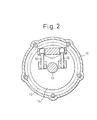
- FIG.2 is a section view taken along line A-A in FIG.1.
- FIG.3 is a section view taken along line B-B in FIG.1.
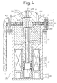
- FIG.4 is a profile cross-sectional view of the displacement control valve.
- FIG.5 is a profile cross-sectional view of the whole compressor in the second embodiment.
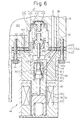
- FIG.6 is a profile cross-sectional view of the displacement control valve.
- FIG.7 is a profile cross-sectional view of the displacement control valve in the third embodiment.
-
- The first embodiment, in which the present invention is embodied in a compressor of variable displacement type, is described below with reference to FIG.1 through FIG.4. Carbon dioxide is used as refrigerant in the present invention.
- As shown in FIG.1, a rotating
shaft 13 is supported by acylinder block 11 and afront housing 12 that form acontrol pressure chamber 121. The rotatingshaft 13 receives a rotational drive force from an external power source (a vehicle engine, for example). Not only is arotary support 14 fixed to the rotatingshaft 13 but, also, aswash plate 15 is supported by the rotatingshaft 13 so that the swash plate can slide, move, and incline in the axial direction of the rotatingshaft 13. As shown in FIG.2, a pair ofguide pins 16 is fixed to theswash plate 15. Theguide pins 16 fixed to theswash plate 15 are slidably inserted intoguide holes 141 formed on therotary support 14. By engagement with theguide holes 141 and theguide pins 16, theswash plate 15 can move and incline in the axial direction of the rotatingshaft 13 and rotate integrally with the rotatingshaft 13. Inclination and movement of theswash plate 15 is guided by the relationship between theguide holes 141 and theguide pins 16, and the slide supporting action of the rotatingshaft 13. - As shown in FIG.1, plural cylinder bores 111 (although only one is shown in FIG.1, five are used in this embodiment as shown in FIG.3) are arranged around the rotating
shaft 13 in thecylinder block 11. Apiston 17 is housed in eachcylinder bore 111. The rotational motion of theswash plate 15, which rotates integrally with the rotatingshaft 13, is converted into a reciprocating motion of thepiston 17 viashoes 18, and thepistons 17 move back and forth in thecylinder bores 111. - A
suction chamber 191 and adischarge chamber 192 are defined and formed in arear housing 19. The refrigerant in thesuction chamber 191, which is a suction pressure area, flows into thecylinder bore 111, after pushing back a suction valve 211 on avalve forming plate 21, from asuction port 201 on avalve plate 20, due to the reversing motion (movement from right to left in FIG.1) of thepiston 17. The refrigerant that flows into thecylinder bore 111 is discharged to thedischarge chamber 192, which is a discharge pressure area, from adischarge port 202 on thevalve plate 20, after pushing back adischarge valve 221 on avalve forming plate 22, due to the advancing motion (movement from left to right in FIG.1) of thepiston 17, which is the compression operating body. Thedischarge valve 221 comes into contact with aretainer 231 on aretainer forming plate 23, resulting in a restriction on the opening of thedischarge valve 221. -
Pressure supply passages discharge chamber 192 and thecontrol pressure chamber 121, pass the refrigerant in thedischarge chamber 192 to thecontrol pressure chamber 121. The refrigerant in thecontrol pressure chamber 121 flows out into thesuction chamber 191 through apressure release passage 32 that connects thecontrol pressure chamber 121 and thesuction chamber 191. An electromagneticdisplacement control valve 25 is interposed between thepressure supply passages - The
displacement control valve 25 is controlled by a controller (not shown), which controls the energization and deenergization of thedisplacement control valve 25 based on the passenger compartment temperature detected by a passenger compartment temperature detector (not shown), which detects the passenger compartment temperature in a vehicle, and the target passenger compartment temperature set by a passenger compartment temperature adjuster (not shown). - The inclination angle of the
swash plate 15 is changed based on the pressure control in thecontrol pressure chamber 121. When the pressure in thecontrol pressure chamber 121 increases, the inclination angle of theswash plate 15 decreases, and when the pressure in thecontrol pressure chamber 121 decreases, the inclination angle of theswash plate 15 increases. The supply of refrigerant from thedischarge chamber 192 to thecontrol pressure chamber 121 is controlled by thedisplacement control valve 25. When refrigerant is supplied from thedischarge chamber 192 to thecontrol pressure chamber 121, the pressure in thecontrol pressure chamber 121 increases, and when the supply of refrigerant from thedischarge chamber 192 to thecontrol pressure chamber 121 is terminated, the pressure in thecontrol pressure chamber 121 decreases. That is, the inclination angle of theswash plate 15 is controlled by thedisplacement control valve 25. - FIG.4 shows the internal structure of the
displacement control valve 25, that is, a gas flow control valve. Thedisplacement control valve 25 comprises asolenoid portion 34 and a valve portion 35. Thesolenoid portion 34 comprises acoil 37 contained in ahousing 36, a cylindrical fixediron core 38, a cylindricalmovable iron core 39, and acompression spring 40, which biases themovable iron core 39 in the direction so as to move away from the fixediron core 38. When thecoil 37 is energized with current, an electromagnetic force, which biases themovable iron core 39 to the fixediron core 38 side, is generated. The valve portion 35 comprises a cylindrical guide body 41 fixed to thehousing 36, avalve body 42 of rod shape penetrated through the guide body 41 and the fixediron core 38, and connected and fixed to themovable iron core 39, and a cylindrical valveport forming body 43 fixed to the guide body 41. - An
insertion recess 411 is recessed on anend surface 414 of the guide body 41 and the valveport forming body 43 is inserted into and fixed to theinsertion recess 411. Agas chamber 412 is recessed at the bottom of theinsertion recess 411, and the tip portion of thevalve body 42 protrudes into thegas chamber 412. Agas passage 413 is formed in the guide body 41. Thegas passage 413 runs from theend surface 414 of the guide body 41 to thegas chamber 412 through the inside of the guide body 41. - A
valve port 431 is formed in the valveport forming body 43 so as to penetrate through the center of the cylindrical valveport forming body 43. Thevalve body 42 comes into contact with the end surface of the valveport forming body 43 when thecoil 37 is energized with current, and is arranged at a valve-closing position to shield thevalve port 431 from thegas chamber 412. Thevalve body 42 is moved away from the end surface of the valveport forming body 43 by the spring force of thecompression spring 40 in a state where thecoil 37 is not energized with current, and is arranged at a valve-opening position to connect thevalve port 431 and thegas chamber 412. - The
housing 36 comprises acylindrical portion 363 and alid portion 364 fixed closely to the end portion of thecylindrical portion 363, and the coupling portion between thecylindrical portion 363 and thelid portion 364 is sealed. - The
displacement control valve 25 is installed onto asuitable coupling surface 193 on the outer wall surface of therear housing 19 by tighteningscrews 44. On thecoupling surface 193, aninsertion recess 33 is arranged and the valveport forming body 43 is inserted into theinsertion recess 33 in a situation where thedisplacement control valve 25 is installed to thecoupling surface 193. When the valveport forming body 43 is inserted into theinsertion recess 33, thevalve port 431 is communicated with theinsertion recess 33. Acoupling flange 361 is formed on the circumferential surface of the end portion of thehousing 36 of thedisplacement control valve 25, and anend surface 362 of thecoupling flange 361 and theend surface 414 of the guide body 41 are arranged so that both are on the same plane. - Between the end surfaces 362, 414 and the
coupling surface 193, a ring shapedgasket 45 is interposed so as to surround the valveport forming body 43. Thegasket 45 comprises ametal substrate 451 and rubber sealingelastic layers substrate 451. The sealingelastic layer 452 is in close contact with the end surfaces 362 and 414, and the sealingelastic layer 453 is in close contact with thecoupling surface 193. - A
communication port 454 is installed in thegasket 45 so as to penetrate the sealingelastic layers pressure supply passage 30 and thegas passage 413 are communicated with each other through thecommunication port 454. Thepressure supply passage 31 is communicated with theinsertion recess 33. When thevalve body 42 is at a valve-opening position, thepressure supply passage 30 and thepressure supply passage 31 are communicated with each other through thecommunication port 454, thegas passage 413, thegas chamber 412, thevalve port 431, and theinsertion recess 33, and the refrigerant in thedischarge chamber 192 is sent to thecontrol pressure chambers 121. - As shown in FIG.1, the maximum inclination angle of the
swash plate 15 is defined when theswash plate 15 comes into contact with therotary support 14. The minimum inclination angle of theswash plate 15 is defined when acirclip 24 on therotating shaft 13 comes into contact with theswash plate 15. - The
discharge chamber 192 and thesuction chamber 191 are connected via an externalrefrigerant circuit 26. The refrigerant, which flows out from thedischarge chamber 192 into the externalrefrigerant circuit 26, is fed back to thesuction chamber 191 via acondenser 27, anexpansion valve 28, and anevaporator 29. - The following effects can be obtained in the first embodiment.
- A first gas passage L1 (the symbol is omitted in the figure), comprising the
pressure supply passage 30, thecommunication port 454, thegas passage 413, and thegas chamber 412, is penetrated through thegasket 45. Therefore, the sealingelastic layer 452 of thegasket 45 prevents the refrigerant in the first gas passage L1 from leaking out of the compressor along the end surfaces 362 and 414. Moreover, the sealingelastic layer 453 of thegasket 45 prevents the refrigerant in the first gas passage L1 from leaking out of the compressor along thecoupling surface 193. - The first gas passage L1, comprising the
pressure supply passage 30, thecommunication port 454, thegas passage 413, and thegas chamber 412, is communicated with thedischarge chamber 192, and a second gas passage L2 (the symbol is omitted in the figure), comprising thepressure supply passage 31, theinsertion recess 33, and thevalve port 431, is communicated with thecontrol pressure chamber 121. Therefore, the pressure in the first gas passage L1 is higher than that in the second gas passage L2. The sealingelastic layer 452 prevents the refrigerant in the first gas passage L1 of a higher pressure from flowing into the second gas passage L2 of a lower pressure along theend surface 414 and acircumferential surface 432 of the valveport forming body 43. The sealingelastic layer 453 prevents the refrigerant in the first gas passage L1 from flowing into the second gas passage L2 along thecoupling surface 193 and thecircumferential surface 432 of the valveport forming body 43. Moreover, the sealingelastic layer 452 prevents the refrigerant in the second gas passage L2 from leaking out of the compressor along the end surfaces 362 and 414, and the sealingelastic layer 453 prevents the refrigerant in the second gas passage L2 from leaking out of the compressor along thecoupling surface 193. - A surface S1 (shown in FIG.4) of the sealing
elastic layer 452, which is in close contact with the end surfaces 362 and 414, and a surface S2 (shown in FIG.4) of the sealingelastic layer 453, which is in close contact with thecoupling surface 193, are seal operating portions of thecasket 45. The end surfaces 362 and 414, thecircumferential surface 432 of the valveport forming body 43, and anend surface 433 of the valveport forming body 43 are installing surfaces, opposing therear housing 19, that is, a gas passage forming body, of thedisplacement control valve 25. Thecoupling surface 193, acircumferential surface 331 of theinsertion recess 33, and abottom surface 332 of theinsertion recess 33 are installing surfaces, opposing thedisplacement control valve 25, of therear housing 19. The first gas passage L1 and the second gas passage L2 penetrate through each of the opposing installing surfaces in the surrounded area on each of the installation opposing surfaces surrounded by the seal operating portions S1 and S2 of thegasket 45. Moreover, the first gas passage L1 penetrates through the seal operating portions S1 and S2 of thegasket 45. In such a structure, into which the first gas passage L1 and the second gas passage L2 penetrate, the prevention of communications between the first gas passage L1 and the outside of the compressor, between the second gas passage L2 and the outside of the compressor, and between the first gas passage L1 and the second gas passage L2 can be achieved by only thesingle gasket 45. - The surfaces of the sealing
elastic layers gasket 45 are planes. The entire surface of the plane of the sealingelastic layer 452 can be pressed by pressure and comes into contact with the planes of the end surfaces 362 and 414, and the entire surface of the plane of the sealingelastic layer 453 can be pressed by pressure and comes into contact with the plane of thecoupling surface 193. The coupling between planes has advantages in equalizing the pressure-pressed contact at arbitrary points on the plane, and sealing by thegasket 45 on the planes of the end surfaces 362 and 414, and thecoupling surface 193 has advantages in improving the reliability of the sealing operation. Moreover, damage to the sealing elastic member due to the foaming phenomenon can be suppressed. - For example, when the outer circumferential surface of a column and the inner circumferential surface of a cylinder are pressed by the pressure and made to come into contact with each other for coupling, the portions where the outer circumferential surface of the column and the inner circumferential surface of the cylinder are pressed by pressure and come into contact are limited to only part of the circumferential surface in the circumferential direction. That is, it is impossible for the entire outer circumferential surface of the column and the entire inner circumferential surface of the cylinder to be uniformly pressed by the pressure and come into contact with each other. Therefore, when a ring shaped seal member is interposed between the outer circumferential surface of the column and the inner circumferential surface of the cylinder, it is necessary to elastically transform a thick rubber seal member into a thin one and generate a uniform sealing operation over the entire circumferential surface in the circumferential direction. Employing a thick seal member increases the quantity of the refrigerant of carbon dioxide that permeates the seal member and the damages of the seal member due to the foaming phenomenon.
- Because the entire surface of the plane of the sealing
elastic layer 452 can be uniformly pressed by pressure and comes into contact with the planes of the end surfaces 362 and 414, the thickness of the sealingelastic layer 452 can be reduced. Moreover, because the entire surface of the plane of the sealingelastic layer 453 can be uniformly pressed by pressure and comes into contact with the plane of thecoupling surface 193, the thickness of the sealingelastic layer 453 can also be reduced. Therefore, the quantity of the carbon dioxide refrigerant that permeates the sealingelastic layers elastic layers - The
gasket 45 is formed by baking the sealingelastic layers substrate 451. The thickness of the baked sealingelastic layers elastic layers elastic layers - Next the second embodiment in FIGs.5 and 6 is described below. The same symbols are attached to the same components as in the first embodiment.
- A
valve portion 50 contained in ahousing 59 of adisplacement control valve 46 comprises a valveport forming body 51, apassage forming body 52, avalve body 53, and thecompression spring 40. Anend surface 521 of thepassage forming body 52 is opposing thecoupling surface 193 of therear housing 19 via agasket 45A. Theend surface 521 is the opposing installing surface of thedisplacement control valve 46. - A
valve port 511 is formed in the valveport forming body 51 and thevalve body 53 contained in ahousing chamber 512 in the valveport forming body 51 opens and closes thevalve port 511. Agas passage 48 is formed in the valveport forming body 51 and thepassage forming body 52 so as to communicate with thehousing chamber 512. Agas passage 49 is formed in thepassage forming body 52 so as to communicate with thevalve port 511. Thegas passage 48 communicates with thepressure supply passage 30 via thecommunication port 454 formed in thegasket 45A. Thegas passage 49 communicates with thepressure supply passage 31 via acommunication port 455 formed in thegasket 45A. Moreover, a pressuresensitive passage 58 is formed in thepassage forming body 52. The pressuresensitive passage 58 communicates with thesuction chamber 191 via acommunication port 456 formed in thegasket 45A and agas passage 194 formed in therear housing 19. - A
solenoid portion 54 of thedisplacement control valve 46 comprises acoil 55, a fixediron core 56, and amovable iron core 57, and thevalve body 53 penetrates through the fixediron core 56 and comes into contact with themovable iron core 57. When thecoil 55 is energized with current, thevalve body 53 is biased in the direction so that thevalve body 53 closes thevalve port 511 by overcoming the spring force of thecompression spring 40. When thecoil 55 is not energized with current, thevalve body 53 is arranged at the valve-opening position so that thevalve port 511 is opened to the maximum. - A pressure sensitive means 47 is built in the
displacement control valve 46. The pressure sensitive means 47 comprises a pressuresensitive housing 471, abellows 472, a pressuresensitive chamber 473 defined in the pressuresensitive housing 471 by thebellows 472, and a pressuresensitive spring 474 contained in thebellows 472. - The gas pressure of the refrigerant in the
suction chamber 191 acts on thebellows 472 via thegas passage 194, thecommunication port 456, the pressuresensitive passage 58, and the pressuresensitive chamber 473. Thevalve body 53 is connected to thebellows 472 and thevalve body 53 opens and closes thevalve port 511. The spring force of the pressuresensitive spring 474 acts on thevalve body 53 in a direction so as to open thevalve port 511. The electromagnetic drive force of thecoil 55 of thedisplacement control valve 46 biases thevalve body 53 in the direction so as to close thevalve port 511. Thedisplacement control valve 46 controls the supply of a suction pressure according to the value of the current supplied to thecoil 55. Thecoil 55 receives the excitation and demagnetization control of the controller (not shown), and the controller controls the excitation and demagnetization of thedisplacement control valve 46 based on the temperature detected by the passenger compartment temperature detector (not shown) that detects the passenger compartment temperature in the vehicle and based on the target passenger compartment temperature set by the passenger compartment temperature adjuster (not shown). - When the
valve port 511 of thedisplacement control valve 46 is open, the refrigerant in thedischarge chamber 192 is sent to thecontrol pressure chamber 121 via thevalve port 511 and thepressure supply passages coil 55 is raised, the opening of the valve decreases, and the flow rate of the refrigerant supplied from thedischarge chamber 192 to thecontrol pressure chamber 121 decreases. Because the refrigerant in thecontrol pressure chamber 121 flows out into thesuction chamber 191 through thepressure release passage 32, the pressure in thecontrol pressure chamber 121 drops. Therefore, the inclination angle of theswash plate 15 increases and the discharge displacement increases. The increase in the discharge displacement causes the suction pressure to drop. When the value of the supplied electric current is lowered, the opening of the valve increases and the flow rate of refrigerant supplied from thedischarge chamber 192 to thecontrol chamber 121 increases. Therefore, the pressure in thecontrol pressure chamber 121 is raised, the inclination angle of theswash plate 15 decreases and the discharge displacement decreases. The decrease of the discharge displacement causes the suction pressure to increase. - The relative position of the
valve body 53 with respect to thevalve port 511, that is, the opening of the valve, is influenced by the gas pressure of the refrigerant in thesuction chamber 191. The gas pressure of the refrigerant in thesuction chamber 191 reflects the thermal load. The larger the thermal load is, that is, the higher the gas pressure of the refrigerant in thesuction chamber 191 is, the larger the contraction, due to the gas pressure, thebellows 472 suffers. In other words, as the thermal load becomes larger, thevalve body 53 moves in the direction so as to close thevalve port 511, and the opening of the valve decreases. Therefore, the inclination angle of theswash plate 15 increases because the flow rate of refrigerant supplied from thedischarge chamber 192 to thecontrol pressure chamber 121 decreases, and the discharge displacement increases. The increase in the discharge displacement causes the thermal load to decrease. On the contrary, as the thermal load becomes smaller, thevalve body 53 moves in the direction so as to open thevalve port 511 and the opening of the valve increases. Therefore, the inclination angle of theswash plate 15 decreases because the flow rate of refrigerant supplied from thedischarge chamber 192 to thecontrol pressure chamber 121 increases, and the discharge displacement decreases. The decrease of the discharge displacement causes the thermal load to increase. - The
gasket 45A, which is interposed between thedisplacement control valve 46 that carries out the displacement control as mentioned above and therear housing 19, carries out the same function as that of thegasket 45 in the first embodiment. Moreover, thegasket 45A prevents the refrigerant from leaking out of the compressor from the pressuresensitive passage 58 and leaking from thepressure supply passages sensitive passage 58 and apassage 194. - Next, the third embodiment in FIG.7 will be described. The same symbols are attached to the same components as those in the first embodiment.
- In this embodiment, a gasket 45B that has a small diameter and a ring shape, and a
gasket 45C that has a large diameter and a ring shape are used. The diameter of an outercircumferential edge 457 of the gasket 45B is made smaller than that of an innercircumferential edge 458 of thegasket 45C, and thepressure supply passage 30 and thegas passage 413 are communicated by the space between the outercircumferential edge 457 of the gasket 45B and the innercircumferential edge 458 of thegasket 45C. - In the present invention, the following embodiments can be realized.
- (1) Seal members made of only sealing elastic materials are used.
- (2) Seal members made of only sealing elastic materials are fixed to the opposing installing surfaces of the gas flow control valve side.
- (3) Seal members made of only sealing elastic materials are fixed to the opposing installing surfaces of the main body side of the compressor.
- (4) The present invention is applied to a
compressor of a variable displacement type, in which a
displacement control valve is interposed on the
pressure release passage 32 so that the movement of the refrigerant from thecontrol pressure chamber 121 to thesuction chamber 191 is controlled thereby. - (5) The present invention is applied to a gas flow control valve (that is, a relief valve), which allows part of the refrigerant in the discharge pressure area to escape to the suction pressure area when the pressure in the discharge pressure area becomes abnormally high.
-
- As described in detail above, the present invention can be expected to bring an excellent effect in that the number of seal members can be reduced because the first gas passage and the second gas passage are made to penetrate through each opposing installing surface in the surrounded area on each opposing installing surface surrounded by the seal operating portions of the seal members, and at least either the first gas passage or the second gas passage is made to penetrate through the seal operating portions of the seal members.
- The present invention, in which the seal operating portions of the seal members are plane, will bring about an excellent effect in that an abnormal gas flow due to damage to the seal members relating to the gas flow control valve can be prevented.
- While the invention has been described by reference to specific embodiments chosen for the purpose of illustration, it should be apparent that numerous modifications could be made thereto by those skilled in the art without departing from the scope of the invention.
Claims (5)
- A gas passage structure in a compressor in which a compression operating body is moved by the rotation of a rotating shaft (13), a gas flow control valve (25, 46) that controls the gas flow in a gas passage within a main body of the compressor that compresses and discharges the gas by means of the action of the compression operating body, is provided and the gas flow control valve is attached to the main body of the compressor so as to oppose a gas passage forming body (19) that forms the gas passage, wherein:a seal means that is formed by one seal member or plural seal members is interposed between the installing surfaces (193, 331, 332), opposing the gas flow control valve, on the gas passage forming body side, and the installing surfaces (362, 414, 411, 432, 433), opposing the gas passage forming body, on the gas flow control valve side;a first gas passage (30, 454, 413, 412) that passes within the gas passage forming body and the gas flow control valve is connected to an inner valve port (431, 511) of the gas flow control valve;a second gas passage (31, 33) that passes within the gas passage forming body and the gas flow control valve is connected to the valve port of the gas flow control valve so that the second gas passage is communicated with the first gas passage via the valve port;the first gas passage and the second gas passage penetrate through each of the opposing installing surfaces in the surrounded area on each of the opposing installing surfaces surrounded by the seal operating portions (s1, s2) of the seal member or plural seal members; andat least either the first gas passage or the second gas passage penetrates through the seal operating portions of the seal member or plural seal members.
- A gas passage structure in a compressor, as set forth in claim 1, wherein the seal means comprises plural seal members one of which has a small diameter and a ring shape and another of which has a large diameter and a ring shape, and a gas passage is formed between the inner circumferential edge (458) of the large diameter ring-shaped seal member (45B) and the outer circumferential edge (457) of the small diameter ring-shaped seal member (45C).
- A gas passage structure in a compressor, as set forth either in claim 1 or claim 2, wherein the seal operating portions of the seal member or the plural seal members on each of the opposing installing surfaces are plane.
- A gas passage structure in a compressor, as set forth either in claim 1 to claim 3, wherein the seal member is a gasket (45, 45A, 45B, 45C) comprising a substrate (451), to both surfaces of which sealing elastic materials (452, 453) are fixed.
- A gas passage structure in a compressor, as set forth in any one of claim 1 to claim 4;wherein the compressor is a compressor of a variable displacement type,which comprises a swash plate (15) contained in the control pressure chamber (121) so that integral rotation with the rotating shaft is allowed and the inclination angle thereof with respect to the rotating shaft can be varied, and plural pistons (17), which are arranged around the rotating shaft and perform reciprocating motion in accordance with the inclination angle of the swash plate, andin which gas is supplied from the discharge pressure area (192) to the control pressure chamber via the pressure supply passage (30, 31), gas is released from the control pressure chamber to the suction pressure area (191) via the pressure release passage (32) to control the pressure in the control pressure chamber, the inclination angle of the swash plate is increased by pressure drop in the control pressure chamber and the inclination angle of the swash plate is decreased by a pressure increase in the control pressure chamber; andwherein the gas flow control valve (25, 46) controls the gas flow in the pressure supply passage or the gas flow in the pressure release passage.
Applications Claiming Priority (2)
| Application Number | Priority Date | Filing Date | Title |
|---|---|---|---|
| JP2000306180A JP2002115659A (en) | 2000-10-05 | 2000-10-05 | Gas flow passage structure of compressor |
| JP2000306180 | 2000-10-05 |
Publications (3)
| Publication Number | Publication Date |
|---|---|
| EP1195522A2 true EP1195522A2 (en) | 2002-04-10 |
| EP1195522A3 EP1195522A3 (en) | 2003-07-09 |
| EP1195522B1 EP1195522B1 (en) | 2006-04-12 |
Family
ID=18786913
Family Applications (1)
| Application Number | Title | Priority Date | Filing Date |
|---|---|---|---|
| EP01123253A Expired - Lifetime EP1195522B1 (en) | 2000-10-05 | 2001-10-02 | Sealing structure for capacity control valve |
Country Status (4)
| Country | Link |
|---|---|
| US (1) | US6568915B2 (en) |
| EP (1) | EP1195522B1 (en) |
| JP (1) | JP2002115659A (en) |
| DE (1) | DE60118682T2 (en) |
Families Citing this family (2)
| Publication number | Priority date | Publication date | Assignee | Title |
|---|---|---|---|---|
| JP2007138785A (en) * | 2005-11-16 | 2007-06-07 | Toyota Industries Corp | Control device for vehicular refrigeration circuit, variable displacement compressor and control valve for variable displacement compressor |
| CN115182870B (en) * | 2022-07-18 | 2024-01-16 | 西南石油大学 | Streamline air passage structure for reciprocating compression cylinder |
Citations (1)
| Publication number | Priority date | Publication date | Assignee | Title |
|---|---|---|---|---|
| JPH06336978A (en) | 1993-03-31 | 1994-12-06 | Toyota Autom Loom Works Ltd | Control valve for variable displacement compressor |
Family Cites Families (7)
| Publication number | Priority date | Publication date | Assignee | Title |
|---|---|---|---|---|
| US2911183A (en) * | 1955-04-07 | 1959-11-03 | Baso Inc | Magnetic valves |
| JPS6282282A (en) * | 1985-10-02 | 1987-04-15 | Toyoda Autom Loom Works Ltd | Variable capacity compressor |
| JPH01190972A (en) * | 1988-01-25 | 1989-08-01 | Nippon Soken Inc | Variable displacement swash plate-type compressor |
| JP3114398B2 (en) * | 1992-11-12 | 2000-12-04 | 株式会社豊田自動織機製作所 | Oscillating swash plate type variable displacement compressor |
| JP3293357B2 (en) * | 1994-09-09 | 2002-06-17 | 株式会社豊田自動織機 | Reciprocating compressor |
| JPH09209960A (en) | 1996-01-31 | 1997-08-12 | Toyota Autom Loom Works Ltd | Valve |
| JP3820766B2 (en) * | 1998-03-06 | 2006-09-13 | 株式会社豊田自動織機 | Compressor |
-
2000
- 2000-10-05 JP JP2000306180A patent/JP2002115659A/en active Pending
-
2001
- 2001-09-28 US US09/965,986 patent/US6568915B2/en not_active Expired - Fee Related
- 2001-10-02 EP EP01123253A patent/EP1195522B1/en not_active Expired - Lifetime
- 2001-10-02 DE DE60118682T patent/DE60118682T2/en not_active Expired - Lifetime
Patent Citations (1)
| Publication number | Priority date | Publication date | Assignee | Title |
|---|---|---|---|---|
| JPH06336978A (en) | 1993-03-31 | 1994-12-06 | Toyota Autom Loom Works Ltd | Control valve for variable displacement compressor |
Also Published As
| Publication number | Publication date |
|---|---|
| US20020041810A1 (en) | 2002-04-11 |
| EP1195522B1 (en) | 2006-04-12 |
| JP2002115659A (en) | 2002-04-19 |
| DE60118682T2 (en) | 2007-03-15 |
| EP1195522A3 (en) | 2003-07-09 |
| DE60118682D1 (en) | 2006-05-24 |
| US6568915B2 (en) | 2003-05-27 |
Similar Documents
| Publication | Publication Date | Title |
|---|---|---|
| US11754072B2 (en) | Compressor having capacity modulation assembly | |
| EP2366901B1 (en) | Variable displacement compressor | |
| EP2113662B1 (en) | Variable displacement type compressor with displacement control mechanism | |
| KR20000011236A (en) | Variable displacement type swash plate compressor and displacement control valve | |
| KR100212769B1 (en) | Variable volume compressor | |
| US6589022B2 (en) | Compressor having a seal cooling structure in which all refrigerant fluid supplied to the compressor is used to cool compressor shaft seals | |
| US6241483B1 (en) | Variable displacement compressor | |
| US6568915B2 (en) | Gas passage structure with improved seal members in a compressor | |
| JP2000161796A (en) | Air conditioner | |
| US6250094B1 (en) | Air conditioning systems | |
| US20090022604A1 (en) | Suction structure in piston type compressor | |
| JP2014118922A (en) | Variable displacement swash plate type compressor | |
| US6572343B2 (en) | Cylinder block for a piston-type compressor with deformation absorbing gaps | |
| US6520748B2 (en) | Variable displacement compressor | |
| EP1275847B1 (en) | Restriction structure in variable displacement compressor | |
| US20090097999A1 (en) | Suction structure in double-headed piston type compressor | |
| US20050220632A1 (en) | Compressor | |
| US20020044872A1 (en) | Piston type compressor | |
| JP2010133331A (en) | Control valve for compressor | |
| JP2003056460A (en) | Passage structure in variable displacement piston type compressor | |
| CN118167645A (en) | Compressor with a compressor body having a rotor with a rotor shaft | |
| JPS5877182A (en) | Variable volume compressor | |
| CN118167643A (en) | Discharge capacity compressor | |
| CN118167644A (en) | Variable capacity compressor | |
| US20050207923A1 (en) | Compressor |
Legal Events
| Date | Code | Title | Description |
|---|---|---|---|
| PUAI | Public reference made under article 153(3) epc to a published international application that has entered the european phase |
Free format text: ORIGINAL CODE: 0009012 |
|
| 17P | Request for examination filed |
Effective date: 20011002 |
|
| AK | Designated contracting states |
Kind code of ref document: A2 Designated state(s): AT BE CH CY DE DK ES FI FR GB GR IE IT LI LU MC NL PT SE TR |
|
| AX | Request for extension of the european patent |
Free format text: AL;LT;LV;MK;RO;SI |
|
| PUAL | Search report despatched |
Free format text: ORIGINAL CODE: 0009013 |
|
| AK | Designated contracting states |
Designated state(s): AT BE CH CY DE DK ES FI FR GB GR IE IT LI LU MC NL PT SE TR |
|
| AX | Request for extension of the european patent |
Extension state: AL LT LV MK RO SI |
|
| 17Q | First examination report despatched |
Effective date: 20031020 |
|
| AKX | Designation fees paid |
Designated state(s): DE FR IT |
|
| GRAP | Despatch of communication of intention to grant a patent |
Free format text: ORIGINAL CODE: EPIDOSNIGR1 |
|
| GRAS | Grant fee paid |
Free format text: ORIGINAL CODE: EPIDOSNIGR3 |
|
| GRAA | (expected) grant |
Free format text: ORIGINAL CODE: 0009210 |
|
| AK | Designated contracting states |
Kind code of ref document: B1 Designated state(s): DE FR IT |
|
| PG25 | Lapsed in a contracting state [announced via postgrant information from national office to epo] |
Ref country code: IT Free format text: LAPSE BECAUSE OF FAILURE TO SUBMIT A TRANSLATION OF THE DESCRIPTION OR TO PAY THE FEE WITHIN THE PRESCRIBED TIME-LIMIT;WARNING: LAPSES OF ITALIAN PATENTS WITH EFFECTIVE DATE BEFORE 2007 MAY HAVE OCCURRED AT ANY TIME BEFORE 2007. THE CORRECT EFFECTIVE DATE MAY BE DIFFERENT FROM THE ONE RECORDED. Effective date: 20060412 |
|
| REF | Corresponds to: |
Ref document number: 60118682 Country of ref document: DE Date of ref document: 20060524 Kind code of ref document: P |
|
| ET | Fr: translation filed | ||
| PLBE | No opposition filed within time limit |
Free format text: ORIGINAL CODE: 0009261 |
|
| STAA | Information on the status of an ep patent application or granted ep patent |
Free format text: STATUS: NO OPPOSITION FILED WITHIN TIME LIMIT |
|
| 26N | No opposition filed |
Effective date: 20070115 |
|
| PGFP | Annual fee paid to national office [announced via postgrant information from national office to epo] |
Ref country code: FR Payment date: 20101020 Year of fee payment: 10 |
|
| PGFP | Annual fee paid to national office [announced via postgrant information from national office to epo] |
Ref country code: DE Payment date: 20100929 Year of fee payment: 10 |
|
| PGFP | Annual fee paid to national office [announced via postgrant information from national office to epo] |
Ref country code: IT Payment date: 20101016 Year of fee payment: 10 |
|
| REG | Reference to a national code |
Ref country code: FR Ref legal event code: ST Effective date: 20120629 |
|
| PG25 | Lapsed in a contracting state [announced via postgrant information from national office to epo] |
Ref country code: DE Free format text: LAPSE BECAUSE OF NON-PAYMENT OF DUE FEES Effective date: 20120501 |
|
| REG | Reference to a national code |
Ref country code: DE Ref legal event code: R119 Ref document number: 60118682 Country of ref document: DE Effective date: 20120501 |
|
| PG25 | Lapsed in a contracting state [announced via postgrant information from national office to epo] |
Ref country code: FR Free format text: LAPSE BECAUSE OF NON-PAYMENT OF DUE FEES Effective date: 20111102 Ref country code: IT Free format text: LAPSE BECAUSE OF NON-PAYMENT OF DUE FEES Effective date: 20111002 |