EP1195460A2 - Ultrasonic cleaning apparatus and ultrasonic cleaning method - Google Patents
Ultrasonic cleaning apparatus and ultrasonic cleaning method Download PDFInfo
- Publication number
- EP1195460A2 EP1195460A2 EP01122639A EP01122639A EP1195460A2 EP 1195460 A2 EP1195460 A2 EP 1195460A2 EP 01122639 A EP01122639 A EP 01122639A EP 01122639 A EP01122639 A EP 01122639A EP 1195460 A2 EP1195460 A2 EP 1195460A2
- Authority
- EP
- European Patent Office
- Prior art keywords
- ultrasonic
- ultrasonic oscillator
- cleaning apparatus
- resonance frequency
- oscillator
- Prior art date
- Legal status (The legal status is an assumption and is not a legal conclusion. Google has not performed a legal analysis and makes no representation as to the accuracy of the status listed.)
- Granted
Links
Images





Classifications
-
- B—PERFORMING OPERATIONS; TRANSPORTING
- B06—GENERATING OR TRANSMITTING MECHANICAL VIBRATIONS IN GENERAL
- B06B—METHODS OR APPARATUS FOR GENERATING OR TRANSMITTING MECHANICAL VIBRATIONS OF INFRASONIC, SONIC, OR ULTRASONIC FREQUENCY, e.g. FOR PERFORMING MECHANICAL WORK IN GENERAL
- B06B1/00—Methods or apparatus for generating mechanical vibrations of infrasonic, sonic, or ultrasonic frequency
- B06B1/02—Methods or apparatus for generating mechanical vibrations of infrasonic, sonic, or ultrasonic frequency making use of electrical energy
- B06B1/0207—Driving circuits
- B06B1/0223—Driving circuits for generating signals continuous in time
- B06B1/0238—Driving circuits for generating signals continuous in time of a single frequency, e.g. a sine-wave
- B06B1/0246—Driving circuits for generating signals continuous in time of a single frequency, e.g. a sine-wave with a feedback signal
- B06B1/0253—Driving circuits for generating signals continuous in time of a single frequency, e.g. a sine-wave with a feedback signal taken directly from the generator circuit
-
- B—PERFORMING OPERATIONS; TRANSPORTING
- B08—CLEANING
- B08B—CLEANING IN GENERAL; PREVENTION OF FOULING IN GENERAL
- B08B3/00—Cleaning by methods involving the use or presence of liquid or steam
- B08B3/04—Cleaning involving contact with liquid
- B08B3/10—Cleaning involving contact with liquid with additional treatment of the liquid or of the object being cleaned, e.g. by heat, by electricity or by vibration
- B08B3/12—Cleaning involving contact with liquid with additional treatment of the liquid or of the object being cleaned, e.g. by heat, by electricity or by vibration by sonic or ultrasonic vibrations
-
- B—PERFORMING OPERATIONS; TRANSPORTING
- B08—CLEANING
- B08B—CLEANING IN GENERAL; PREVENTION OF FOULING IN GENERAL
- B08B7/00—Cleaning by methods not provided for in a single other subclass or a single group in this subclass
- B08B7/02—Cleaning by methods not provided for in a single other subclass or a single group in this subclass by distortion, beating, or vibration of the surface to be cleaned
- B08B7/026—Using sound waves
- B08B7/028—Using ultrasounds
-
- D—TEXTILES; PAPER
- D06—TREATMENT OF TEXTILES OR THE LIKE; LAUNDERING; FLEXIBLE MATERIALS NOT OTHERWISE PROVIDED FOR
- D06F—LAUNDERING, DRYING, IRONING, PRESSING OR FOLDING TEXTILE ARTICLES
- D06F19/00—Washing machines using vibrations for washing purposes
Definitions
- the present invention relates to an ultrasonic cleaning apparatus, more specifically to a household ultrasonic cleaning apparatus for cleaning, for example, fabrics, textile products and the like and an ultrasonic cleaning method.
- a control apparatus of a washing machine disclosed in Japanese Patent Laid-Open No. 11(1999)-104388 has been heretofore known.
- a partial cleaning unit which is pressed against dirty portions of clothes and removes the stains is constituted by a piezoelectric element, and electrical signals are supplied to the piezoelectric element by amplifying an amplitude of an output signal of a controller by an amplitude amplifier.
- Power is supplied from a power supplier to the amplitude amplifier, and an operation state of the piezoelectric element is detected by a state detector. Then, the control apparatus controls a frequency of the output signal of the controller so that the piezoelectric element and the amplitude amplifier are synchronized with each other by an output of the state detector.
- an oscillator is dipped in cleaning liquid while dipping the subject to be cleaned in the cleaning liquid, and stains attached to the subject to be cleaned are removed by propagating ultrasonic waves generated in an ultrasonic oscillation circuit to the subject to be cleaned.
- impedance of an oscillation circuit changes along with a change of a depth of the cleaning liquid.
- a secondary output current of a coupling transformer provided between an oscillator and the oscillation circuit drops. Therefore, there has been a problem that an oscillation amplitude of the ultrasonic oscillator becomes small and a cleaning capability of the ultrasonic cleaning apparatus is lowered.
- phase synchronizing oscillator current flowing through an oscillator or a voltage across the oscillator are detected, and a frequency of a voltage control oscillation circuit is controlled so that a phase difference between the detected voltage and the detected current approaches a predetermined level.
- the oscillator is driven while following a resonance frequency or a proper frequency near the resonance frequency.
- a resonance frequency rapidly changes owing to a change of a load when the oscillator is used in cleaning liquid, and hence the resonance point cannot be discriminated from an anti-resonance point.
- the oscillator may be uncontrollable. This is because the current and the voltage show an identical phase in the resonance point and the anti-resonance point and the resonance point and the anti-resonance point cannot be discriminated from each other by the phase synchronizing control.
- An object of the present invention is to provide an ultrasonic cleaning apparatus capable of exhibiting excellent cleaning effects with less power and cleaning dirty clothes easily.
- a first aspect of the present invention is an ultrasonic cleaning apparatus which cleans a subject to be cleaned by oscillations generated by an ultrasonic oscillator, the ultrasonic cleaning apparatus comprising: a power amplifier for amplifying an amplitude of a signal to supply the amplified signal to the ultrasonic oscillator, a phase comparator for determining a difference between a phase of a current flowing through the ultrasonic oscillator and a phase of a voltage applied to the ultrasonic oscillator to generate a voltage in accordance with the phase difference; and a voltage control oscillation device for generating a frequency of the signal in accordance with the voltage generated by the phase comparator and for controlling the frequency so that the phase difference is held within a predetermined phase range, wherein the power supplied to the ultrasonic oscillator is set to a range of 1W to 10W.
- the power supplied to the ultrasonic oscillator is set to the range of 1W to 10W
- the phase comparator generates the voltage in accordance with the phase difference between the current and the voltage.
- the voltage control oscillation device generates the frequency of the signal in accordance with the generated voltage, and controls the frequency so that the phase difference is held within the predetermined phase range. Therefore, effective power supplied to the ultrasonic oscillator can be increased, and influences of the phase shift due to the change of the load can be lessened.
- a second aspect of the present invention is characterized in that the voltage control oscillation device holds the phase difference to a range within ⁇ 30° .
- a third aspect of the present invention is characterized in that a difference between a resonance frequency of the ultrasonic oscillator and an anti-resonance frequency thereof is regulated to be 1 kHz or more.
- the resonance frequency means a frequency at which impedance of the oscillator is the lowest
- the anti-resonance frequency is a frequency close to the resonance frequency, at which the impedance of the oscillator shows a high peak Accordingly, an excellent cleaning effect can be exhibited with less power, and dirty clothes can be cleaned easily.
- the resonance frequency means a frequency at which the oscillation is the largest and the impedance of the oscillator is low
- the anti-resonance frequency is a frequency at which the impedance of the oscillator is high.
- Fig. 1 is a circuit constitution of a first embodiment of an ultrasonic cleaning apparatus according to the present invention.
- Fig. 2 is a diagram explaining a phase difference between a current flowing through an ultrasonic oscillator and a voltage across the ultrasonic oscillator.
- Fig. 3 shows an equivalent circuit of an ultrasonic oscillator of the first embodiment.
- Fig. 4 is a diagram showing an impedance characteristic of the ultrasonic oscillator of the first embodiment for a frequency.
- Fig. 5 is a sectional view showing the first embodiment of the ultrasonic cleaning apparatus according to the present invention.
- Fig. 6 is a front view showing a cover portion and a front ultrasonic phone in the ultrasonic cleaning apparatus of the first embodiment.
- Fig. 7A is a side view of an ultrasonic oscillation portion of the first embodiment
- Fig. 7B is a rear view of a piezoelectric unit of the first embodiment.
- Fig. 8 is a perspective view of an ultrasonic oscillation portion of a first modfication of the first embodiment.
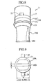
- Fig. 9 is a front view of the ultrasonic oscillation portion of the first modification.
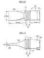
- Fig. 10 is a plan view of the ultrasonic oscillation portion of the first modification.
- Fig. 11 is a side view of the ultrasonic oscillation portion of the first modification.
- Fig. 12 shows a second modification of the ultrasonic oscillator and the ultrasonic phone.
- Figs. 13A and 13B show a third modification of the ultrasonic oscillator and the ultrasonic phone.
- Fig. 14 is a circuit constitution of a second embodiment of the ultrasonic cleaning apparatus according to the present invention.
- Fig. 15 is a circuit constitution of a third embodiment of the ultrasonic cleaning apparatus according to the present invention.
- Fig. 16 is a circuit constitution of a fourth embodiment of the ultrasonic cleaning apparatus according to the present invention.
- Fig. 17 is a circuit constitution of a fifth embodiment of the ultrasonic cleaning apparatus according to the present invention.
- Fig. 18 is a circuit constitution in which a coil for adjusting a difference between a resonance frequency and an anti-resonance frequency is provided between an adjusting circuit and a current detection resistor.
- Fig. 19 is a table illustrating results obtained by measuring an oscillation stability owing to the difference between the resonance frequency and the anti-resonance frequency in the foregoing embodiments.
- the applicant of this application aimed at an oscillation characteristic and power efficiency of an oscillation element, and the optimized condition influenced on a cleaning effect has been found by controlling a phase difference between an alternating voltage and a current for a changing load. Moreover, the applicant aimed at the oscillation characteristic of the oscillation element, and found existence of a proper value between a resonance frequency of the oscillation element and an anti-resonance frequency thereof for a changing load. The applicant found that stable and high efficiency oscillation is made possible by controlling this value properly, and as a result found the optimized condition influenced on the cleaning effect.
- a load state means a state where a subject to be cleaned is in contact with an ultrasonic cleaning apparatus, specifically an ultrasonic cleaning phone.
- no load state means a state where the subject to be cleaned is not in contact with an ultrasonic cleaning apparatus.
- Fig. 1 is a circuit constitution diagram of a first embodiment of the ultrasonic cleaning apparatus according to the present invention.
- the circuit shown in Fig. 1 is a driving circuit for driving an ultrasonic oscillator, which is constituted by a power amplifier 31, a transformer T, an adjusting section 33, an ultrasonic oscillator 16, a phase comparator 37 and a voltage control oscillation device 38.
- the power amplifier 31 has power tranistors Q 1 and Q 2 connected in series with a primary winding of the transformer T disposed therebetween, and the power transistors Q 1 and Q 2 amplify an amplitude of a signal from the voltage control oscillation device 38.
- the power transistors Q 1 and Q 2 supply the amplified signal to the adjusting section 33 via the transformer T.
- the adjusting section 33 is constituted by a coil L m and a capacitor C m that is an impedance element for adjustment, and supplies the signal from the transformer T to the ultrasonic oscillator 16.
- the resistor R is inserted between the transformer T and the oscillator 16, and shows a low resistance.
- a current flowing through the resistor R is detected as a current signal, and input to the phase comparator 37.
- a voltage at one terminal of the ultrasonic oscillator 16 is detected as a voltage signal, and input to the phase comparator 37.
- the phase comparator 37 determines a difference between a phase of the detected current and a phase of the detected voltage, and generates a voltage in accordance with the phase difference.
- the voltage control oscillation device 38 transmits a signal having a frequency in accordance with the voltage generated by the phase comparator 37, and controls the frequency so that the phase difference of the phase comparator 37 is held within ⁇ 30° .
- Fig. 2 a diagram for explaining the phase difference ⁇ between the current I flowing through the ultrasonic oscillator and the voltage V across the ultrasonic oscillator is shown.
- Power supplied to the ultrasonic oscillator 16 is set to a range from 1 W to 10 W. This is because in order to obtain a compact-sized and handy ultrasonic cleaning apparatus, it is intended to make it possible to operate the ultrasonic cleaning apparatus with a battery or a chargeable battery. Noted that the ultrasonic cleaning apparatus may be connected to an electrical outlet directly by use of an AC adapter and the like.
- the ultrasonic oscillator 16 can be illustrated by an equivalent circuit as shown in Fig. 3.
- This equivalent circuit has a series circuit in which a coil L 1 having an inductance component, a capacitor C 1 having a capacitance component and a resistor R 1 are connected in series, and in which a capacitor C 2 is connected in parallel to the series circuit to constitute a parallel circuit.
- the ultrasonic oscillator 16 changes its impedance relative to a change of a frequency as shown in Fig. 4.
- a series resonance is constituted by the coil L 1 and the capacitor C 1 schematically, and a resonance frequency f 1 at which the impedance is minimum is schematically obtained by the formula (1).
- f 1 1/ ⁇ 2 ⁇ (L 1 C 1 ) 1/2 ⁇
- a parallel resonance is constituted by the coil L 1 and the capacitor C 2 schematically, and an anti-resonance frequency f 2 at which the impedance is maximum is obtained by the formula (2) schematically.
- f 2 1/ ⁇ 2 ⁇ (L 1 C 2 ) 1/2 ⁇
- the resonance frequency f 1 is lower than the anti-resonance frequency f 2 as shown in Fig. 3.
- the ultrasonic oscillator 16 is a bolt-tightened "Langevin type piezoelectric oscillator, and its resonance frequency f 1 is set to a range of 20 kHz to 100 kHz.
- a difference ⁇ f between the resonance frequency f 1 of the ultrasonic oscillator 16 and the anti-resonance frequency f 2 thereof is regulated to 1 kHz or more.
- the ultrasonic oscillator 16 can oscillate stably and high efficiently even when a load change occurs. Accordingly, the ultrasonic cleaning apparatus can exhibit an excellent cleaning effect with less power and clean dirty clothes easily.
- the difference ⁇ f is preferably regulated to 12 kHz or more, the effect becomes more significant. More preferably, if the difference ⁇ f is regulated to 15 kHz or more, the effect becomes still more significant.
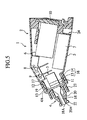
- Fig. 5 is a section view of the ultrasonic cleaning apparatus of the first embodiment according to the present invention.
- Fig. 6 is a front view of a cover portion and a front ultrasonic phone in the ultrasonic cleaning apparatus of the first embodiment.
- the ultrasonic cleaning apparatus 1 is composed of an apparatus body 2, an ultrasonic oscillation portion 3 provided in the apparatus body 2 and a subject to be cleaned guiding cover 4 surrounding the ultrasonic oscillation portion 3.
- the apparatus body 2 has an approximately cylindrical casing 5 which incorporates a battery housing portion 6, a driving circuit 7 for driving the ultrasonic oscillator 16 which corresponds to the driving circuit shown in Fig. 1, a switch portion 8 and a light emission diode 9 as a drive confirmation lamp.
- a reverse cover 10 fitted to an rear end portion of the casing 5 blocks up the battery housing portion 6.
- a male screw portion 12 formed at an external periphery surface of a front end portion of the casing 5 is screwed to a female screw portion 19 formed in the subject to be cleaned guiding cover 4.
- the ultrasonic oscillation portion 3 is supported to a front end opening portion 11 of the casing 5 via a flange member 13, and is composed of the ultrasonic oscillator 16 constituted by joining piezoelectric units 14 and 15, a rear ultrasonic phone 17 jointed to a rear end surface of the ultrasonic oscillator 16, and a front ultrasonic phone 18 jointed to a front end surface of the ultrasonic oscillator 16.
- the piezoelectric units 14 and 15 is connected to the driving circuit 7 with lead wires (not shown), and supplied with power.
- the rear ultrasonic phone 17 and the front ultrasonic phone 18 are made of a metal which can changes a frequency of oscillation of the ultrasonic oscillator 16 to a specific frequency and easily propagate the oscillation of the ultrasonic oscillator 16 to strengthen the oscillation.
- the front ultrasonic phone 18 is composed of a large diameter sub-portion, a tapered sub-portion which reduces its diameter straightly from the large diameter sub-portion, and a small diameter sub-portion, and forwardly protrudes from the front end portion of the casing 5. Noted that the tapered sub-portion may reduce its diameter curvilinearlly or stepwise.
- a sustain portion 21 is formed so as to surround a cover portion 20, and the cover portion 20 is formed so as to surround the front ultrasonic phone 18.
- An external diameter of the cover portion 20 is set so as to be gradually smaller forwardly.
- the front ultrasonic phone 18 is out of contact with the cover portion 20 and a subject to be cleaned guiding ring portion 22 which surrounds the front ultrasonic phone 18.
- the front ultrasonic phone 18 has a structure in which the ultrasonic oscillation thereof is not apt to attenuate.
- the number of the piezoelectric units 14 and 15 may be optional as long as it is more than one, and preferably two or four.
- the flange member 13 is fitted at a position where a node of the oscillation exists, and specifically fitted to the position ahead of the piezoelectric unit 15.
- an ultrasonic oscillation portion 3 As the piezoelectric units 14 and 15, used was the one obtained by carrying out a polarization treatment for a cylindrical piezoelectric unit (diameter: 15 mm and thickness: 4 mm) in its thickness direction, which contains PZT that is solid solution of PbZrO 3 and PbTiO 3 as a main component.
- the ultrasonic oscillation portion 3 the Langevin ultrasonic oscillator was prepared, which was obtained by sandwiching the piezoelectric units 14 and 15 between the front and rear ultrasonic phones 17 and 18 made of aluminum while applying tightening torque of 55 kg ⁇ cm to the piezoelectric units 14 and 15 from the front and rear ultrasonic phones 17 and 18. Noted that, as shown in Fig.
- the length A of the front ultrasonic phone 18 was set to 33 mm; the length B of the ultrasonic oscillator 16, 8 mm; and the length C of the rear ultrasonic phone 17, 19 mm.
- the diameter of the rear ultrasonic phone 17 was set to 15 mm similarly to the piezoelectric units 14 and 15.
- the area S 1 of the tip end plane 18A of the front ultrasonic phone 18 was set to 03 cm 2 . Noted that even if there is a hollow at the tip end portion of the phone, the area S 1 is calculated supposing that there is not a hollow.
- the area S 2 of the piezoelectric units was set to 1.77 cm 2 .
- S 1 is the area of the tip end portion of the front ultrasonic phone 18, that is, a cleaning surface.
- S 2 is a joint area of the piezoelectric unit jointing the phone.
- the sustain portion 21 is formed so as to surround the cover portion 20, and the cover portion 20 is formed so as to surround the front ultrasonic phone 18.
- a dimension of an external diameter of the cover portion 20 is set so as to be smaller forwardly.
- the front ultrasonic phone 18 is out of contact with the subject to be cleaned guiding ring portion 22 and the cover portion 20 which surround the front ultrasonic phone 18, and a structure that the ultrasonic oscillation of the front ultrasonic phone 18 is not apt to attenuate is provided.
- the ultrasonic phone of the ultrasonic oscillation portion 3 shown in Figs. 5 to 7 has a cylindrical shape (hereinafter referred to as a round phone).
- the ultrasonic phone has a flat shape (hereinafter referred to as a flat phone).
- the constitution of this ultrasonic oscillation portion 3 will be described with reference to Figs. 8 to 11.
- the ultrasonic oscillation portion 3 uses a Langevin ultrasonic oscillator (the ultrasonic oscillation portion 3) having the same constitution as that described in the above. Therefore, description for the ultrasonic oscillation portion 3 is omitted.
- the length of the front ultrasonic phone 18A was set to 28 mm
- the length of the rear ultrasonic phone 17 was set to 14 mm.
- the diameter of the rear ultrasonic phone 17 was set to 15 mm similarly to the piczoelectric units 14 and 15, and a step portion 17B having a length of 5 mm in a longitudinal direction of the rear ultrasonic portion 17 was formed on both sides of the rear end portion of the rear ultrasonic phone 17 as shown in Fig. 11.
- An output of 6 W was applied between electrodes 25 and 26 of the element (piezoelectric unit), and a resonance frequency of the oscillator was 50 kHz.
- the tip end of the front ultrasonic phone 18A is flat.
- the tip end plane 18B of the front ultrasonic phone 18A which contacts the subject to be cleaned, has a rectangular shape.
- the length a of the long side (long axis) of the rectangle is set to 15 mm
- the length b of the short side (short axis) thereof is set to 2.5 mm
- the area thereof is set to 37.5 mm 2 .
- the front ultrasonic phone 18A is formed to a shape in which ihe front ultrasonic phone 18A is made to be gradually thinner from its base portion to its tip as shown in Fig. 10.
- the axis ratio R of the length a of the long axis in the tip end plane 18B of the front ultrasonic phone 18A to the length b of the short axis therein should be preferably set to a range of 2 ⁇ R ⁇ 10.
- the tip end plane 18B of the front ultrasonic phone 18A may be elliptical, and if the axis ratio R of the length a of the long axis in the tip end plane 18B to the length b of the short axis therein is set to a range of 2 ⁇ R ⁇ 10, the similar effects can be achieved.
- the front ultrasonic phone 18A is made to be a tapered shape in which its diameter is smaller at a position closer to its tip end plane. With this tapered shape, the maximum value of an oscillation speed can be made to a range of 1m/s to 10 m/s.
- the maximum value of the oscillation speed can be made to a range of 1 m/s to 10 m/s by arranging the ultrasonic oscillator 16 at a boundary between the rear and front ultrasonic phones 17 and 18.
- the oscillation speed When the oscillation speed is set to 1 m/s or less, it is next to impossible to obtain cleaning effects. Furthermore, when the oscillation speed is set to 10 m/s or more under power ranging from 1 W to 10 W, a cleaning plane of a phone is extremely small. The cleaning effect is lessened or the subject to be cleaned is damaged, so that this phone cannot be used for an original cleaning.
- the power supplied from the power amplifier 31 to the ultrasonic oscillator 16 is set to a range of 1 W to 10 W. If the power is below 1 W, an amplitude necessary for cleaning is not obtained. When high power exceeding 10 W is used, a little loss is ignored. Specifically, it is possible to exhibit excellent effects by use of a handy type lower power consumption ultrasonic cleaning apparatus which can be used at home with easiness.
- the phase comparator 37 obtains the phase difference ⁇ between the phase of the detected current 1 and the phase of the detected voltage V, and generates a voltage in accordance with the phase difference ⁇ For example, the phase comparator 37 generates the voltage equivalent to a time difference between a zero cross point of the voltage and a zero cross point of the current.
- the voltage control oscillation device 38 generates a signal having a frequency in accordance with the voltage generated by the phase comparator 37, and controls the frequency so that the phase difference ⁇ obtained by the phase detector 37 is kept within ⁇ 30° . Accordingly, effective power supplied to the ultrasonic oscillator 16 can be increased, and influences of the phase shift due to the change of the load can be lessened.
- a breakdown limit of the ultrasonic oscillator 16 is 0.8 m/s of the oscillation speed at its operation end plane (tip end plane), when the ultrasonic oscillator 16 is an ordinary piezoelectric element. Therefore, as shown in Fig. 5, the rear and front ultrasonic phones 17 and 18 for amplifying the oscillation speed were jointed to the ultrasonic oscillator 16, and the maximum value of the oscillation speed at the tip end plane of the front ultrasonic phone 18 was set to a range of 1 m/s to 10 m/s.
- an amplitude increasing means such as an ultrasonic phone, it is possible to increase the oscillation speed of the ultrasonic oscillator 16 to 1.2 to 12 times as high as that of the ordinary piezoelectric element, whereby the cleaning effects can be further enhanced.
- this ultrasonic cleaning apparatus further comprises a load state deciding section 40 for deciding based on a detected current and a detected voltage whether the loads are applied or not, in addition to the constituent components of the ultrasonic cleaning apparatus of the first embodiment shown in Fig. 1.
- the power amplifier 31 reduces power supplied to the ultrasonic oscillator 16 to approximately half as low as that of power or less in a state where the loads are applied.
- the load state deciding section 40 decides based on a detected current and a detected voltage whether the loads are applied or not. In the state where no load is applied, since impedance indicated by a voltage effective value/a current effective value is equal to 100 ⁇ or less, it is decided depending on the impedance whether the loads are applied or not. Noted that the impedance during a cleaning operation ranges from 150 to 900 ⁇ and impedance varies depending on elements.
- the power amplifier 31 decrease the power supplied to the ultrasonic oscillator 16 to approximately half as high as that of the power or less when the load are applied. Accordingly, the total power consumed in a unit cleaning operation is improved by about 30%, and it is possible to reduce heat generation of the circuit and heat generation of the elements due to waste power.
- the power per the unit cleaning operation was 5 W ⁇ h
- a temperature of the circuit was 85 °C
- a temperature of the element was 60 °C.
- the power per the unit cleaning operation was 35 W ⁇ h
- a temperature of the circuit was 50 °C and a temperature of the element was 40 °C.
- the unit cleaning operation was performed for 15 sec and the ultrasonic cleaning apparatus was raised for 5 sec. These operations were performed for 30 minutes continuously.
- the switch SW was in a dose state and no load was applied.
- the temperature of the circuit is measured by transistors and a transformer, which are circuit components generating heat.
- the temperature of the element is a temperature of the oscillator, and the element generates heat if the power is not reduced when no load is applied.
- this ultrasonic cleaning apparatus further comprises a load state deciding section 40 for deciding based on a detected current and a detected voltage whether a load is applied or not, in addition to the constituent components shown in Fig. 1.
- a voltage control oscillation device 38 controls the phase difference to 60° or more by controlling the frequency, when no load is applied.
- the load state deciding section 40 decides based on the detected current and the detected voltage whether the load is applied or not. Since the decision of the load state is the same as that described in the second embodiment, descriptions are omitted.
- the voltage control oscillation device 38 controls the phase difference ⁇ to 60° or more by controlling the frequency.
- this ultrasonic cleaning apparatus comprises a switching transistor Q 3 connected in series to the capacitor C m as a waveform shaping capacitor, and a switch control section 45 for controlling the turning ON/OFF of the switching transistor Q 3 , in addition to the constituent components of the ultrasonic cleaning apparatus shown in Fig. 1.
- the switch control section 45 Based on the detected current value and the detected voltage value and an output from the phase comparator 37, the switch control section 45 keeps the switching transistor Q 3 in turning-off state until the phase difference between the phase of the voltage and the phase of the current of the ultrasonic oscillator 16 becomes equal to a predetermined value, for example, 30°. After the phase difference becomes equal to the predetermined value, the switch control section 45 controls so as to tum-on the switching transistor Q 3 .
- capacitance of the series capacitor constituted by the capacitor C m and the switching transistor Q 3 is made to about 1/2 of the capacitor C m or less, and a current flowing through the capacitor C m can be reduced. Thus, it is possible to save the power.
- a response time is set to 02 second or less, which is necessary for matching the phase difference between the current flowing through the ultrasonic oscillator 16 and the voltage across therethrough with the predetermined value, a response characteristic may be improved.
- a duty ratio of on-time to off-time of a signal in the voltage control oscillation device 38 may be set to approximately 1/4 or less until the phase difference between the voltage and the current becomes equal to the predetermined value.
- Fig. 17 is a circuit constitution of the fifth embodiment of the ultrasonic cleaning apparatus according to the present invention.
- an adjusting coil L p and an adjusting capacitor C p are connected in parallel to both end terminals of the ultrasonic oscillator 16, and a difference between a resonance frequency and an anti-resonance frequency of a synthesis circuit constituted by the adjusting coil L p , the adjusting capacitor C p and the ultrasonic oscillator 16 is adjusted to 1 kHz or more when the difference between the resonance frequency and the anti-resonance frequency of the ultrasonic oscillator 16 is 1 kHz or less.
- C is schematically a synthesis capacitance obtained by adding C 1 and C 2 to each other in the equivalent circuit shown in Fig. 3.
- the anti-resonance frequency is schematically represented by the formula (3), and hence the anti-resonance frequency changes.
- the value of the adjusting coil L p and the value of the adjusting capacitor C p should be adjusted respectively so that the anti-resonance frequency becomes higher than that before the adjustment.
- the adjusting coil L p is connected to the ultrasonic oscillator 16 and the value of the adjusting coil L p is adjusted.
- the difference between the resonance frequency and the anti-resonance frequency may be adjusted to 1 kHz or more, preferably to 1.2 kHz or more, and more preferably to 1.5 kHz or more.
- the adjusting capacitor C p is connected to the ultrasonic oscillator 16, and the value of the adjusting capacitor C p is adjusted.
- the difference between the resonance frequency and the anti-resonance frequency may be adjusted to 1 kHz or more, preferably to 1.2 kHz or more, and more preferably to 1.5 kHz or more.
- the adjusting coil L p and the adjusting capacitor C p are connected in parallel to both end terminals of the ultrasonic oscillator 16, and the difference between the resonance frequency of the synthesis circuit and the anti-resonance frequency thereof, which is constituted by the adjusting coil L p , the adjusting capacitor C p and the ultrasonic oscillator 16, is adjusted to 1 kHz or more, so that even if the load varies, stable oscillation is possible with a high efficiency. Accordingly, the ultrasonic cleaning apparatus of the present invention exhibits excellent cleaning effect with less power, and dirty clothes can be easily cleaned.
- the difference between the resonance frequency and the anti-resonance frequency is preferably adjusted to 1.2 kHz or more, the effects become more significant.
- the difference between the resonance frequency and the anti-resonance frequency is more preferably adjusted to 1.5 kHz or more, the effects become still more significant.
- the applicant of the present invention measured stability of the oscillation by the difference between the resonance frequency and the anti-resonance frequency. The measurement results are shown in Fig. 19.
- Examples 4 to 8 correspond to the case of the ultrasonic oscillator 16 of the fifth embodiment.
- Example 4 corresponds to the case where an adjusting coil of 15 mH is connected to the ultrasonic oscillator of Example 3. The difference between the resonance frequency and the anti-resonance frequency is adjusted to 15 kHz, and the oscillation stability is the best (o ⁇ ).
- a thickness of the piezoelectric element is 2 mm, and no adjusting coil is used.
- C f is 1750 pF, and the difference between the resonance frequency and the anti-resonance frequency is adjusted to 0.5 kHz, so that the oscillation stability is rather bad ( ⁇ ).
- Example 6 corresponds to the case where an adjusting coil of 3.2 mH is connected to the ultrasonic oscillator of Example 5.
- Example 7 corresponds to the case where an adjusting coil of 6 mH is connected to the ultrasonic oscillator of Example 5.
- the difference between the resonance frequency and the anti-resonance frequency is adjusted to 15 kHz, and the oscillation stability is the best (o ⁇ ).
- Example 8 corresponds to the case where an adjusting coil of 10 mH is connected to the ultrasonic oscillator of Example 5.
- the difference between the resonance frequency and the anti-resonance frequency is adjusted to 1.2 kHz, and the oscillation stability is good ( ⁇ ).
- the value of the adjusting coil should be preferably set to a range from 5 mH to 200 mH.
- the capacitance value of the ultrasonic oscillator should preferably set to a range of 10 pF to 3000 pF.
- the power supplied to the ultrasonic oscillator is adjusted to a range from 1 W to 10 W, and the phase comparator generates the voltage in accordance with the phase difference between the current and the voltage.
- the voltage control osciation device generates the frequency of the signal in accordance with the generated voltage, and controls the frequency so that the phase difference is kept at ⁇ 30° . Accordingly, the effective power applied to the ultrasonic oscillator can be increased, and influences of the phase difference due to the variation of the load can be lessened. As a result, the ultrasonic cleaning apparatus of the present invention can exhibit excellent cleaning effects with less power, and can clean dirty clothes easily.
- the ultrasonic phone connected to the ultrasonic oscillator amplifies the oscillation speed, and the maximum value of the oscillation speed in the tip end plane of the ultrasonic phone is set to a range from 1m/s to 10m/s. Therefore, it is possible to farther enhance the cleaning effects.
- the present invention it is decided based on the detected current and the detected voltage whether the load is applied or not.
- the power supplied to the ultrasonic oscillator is made to be half that of in the load application state or less. Therefore, it is possible to achieve the power saving.
- the phase difference is controlled to 60° or more by controlling the frequency, and the effective power can be reduced to 1/2 or less. Therefore, the power saving can be achieved.
- the power supplied to the ultrasonic oscillator is set to a range from 1W to 10W, and the difference between the resonance frequency of the ultrasonic oscillator and the anti-resonance frequency thereof is adjusted to 1 kHz or more.
- the power supplied to the ultrasonic oscillator is set to a range from 1W to 10W, and at least one passive element of the coil and the capacitor is connected in parallel to the ultrasonic oscillator.
- the difference between the resonance frequency of the synthesis circuit and the anti-resonance frequency thereof, which is constituted by the passive element and the ultrasonic oscillator, is adjusted to 1 kHz or more.
- the ultrasonic oscillator is the Langevin type piezoelectric oscillator, and the resonance frequency of the ultrasonic oscillator is set to a range from 20 kHz to 100 kHz. Accordingly, the cleaning efficiency is high, and the excellent effect can be exhibited with less power, and the dirty clothes and the like can be easily cleaned.
- the value of the coil is set to a range from 5 to 200 mH and the value of the capacitor is set to a range of 10 to 3000 pF, the difference between the resonance frequency of the ultrasonic oscillator and the anti-frequency thereof is adjusted to 1 kHz or more.
- the load varies, the stable and high efficiency oscillation is possible. Therefore, the excellent cleaning effect can be exhibited with less power, and the dirty clothes and the like can be easily cleaned.
- the detector is provided among the adjusting circuit, the ultrasonic oscillator and the passive element, the stable and high efficiency oscillation is possible. Accordingly, the excellent cleaning effects can be exhibited with less power, and the dirty clothes and the like can be easily cleaned.
- the present invention is not limited to the ultrasonic cleaning apparatus of the first to fifth embodiments.
- the phase difference between the phase of the voltage of the ultrasonic oscillator 16 and the phase of the current thereof is compared, and the frequency of the signal is controlled based on the phase difference.
- the frequency of the signal may be controlled based on one of the current value of the ultrasonic oscillation 16 and the voltage value thereof.
- the adjusting section 33 is provided.
- this adjusting section 33 may be omitted.
- the resistor R is used for the resistor for the current detection.
- a current probe and the like may be used in stead of the resistor R.
- the materials forming the front ultrasonic phone 18 and the rear ultrasonic phone 17 were made to be identical, and the front ultrasonic phone 18 and the rear ultrasonic phone 17 were made to possess the same ultrasonic oscillation characteristic.
- the strong detergency was obtained by getting large oscillation energy.
- the front ultrasonic phone 18 and the rear ultrasonic phone 17 may be designed so that the front ultrasonic phone 18 and the rear ultrasonic phone 17 have approximately the identical ultrasonic oscillation characteristic.
- the materials showing approximately the same ultrasonic oscillation characteristic mean the ones having compositions equal to each other by 90% or more. Incidentally, in the materials showing the different ultrasonic oscillation characteristics, since propagation speeds of the oscillation are different from each other, balance is apt to be lost owing to the oscillation, and it is impossible to get large oscillation energy.
- the front ultrasonic phone 18 and the rear ultrasonic phone 17 are made from aluminum, other metals such as stainless and alloys can be employed.
- a nonmetallic material can be used as the materials of the from ultrasonic phone 18 and the rear ultrasonic phone 17.
- the nonmetallic material there have been, for example, ceramics such as glass, alumina and zirconia, plastics such as polystyrene, ABS and Bakelite, and composites consisting of them.
- a sound propagation speed should be equal to 2000 m/sec or more.
Landscapes
- Engineering & Computer Science (AREA)
- Textile Engineering (AREA)
- Mechanical Engineering (AREA)
- Apparatuses For Generation Of Mechanical Vibrations (AREA)
- Accessory Of Washing/Drying Machine, Commercial Washing/Drying Machine, Other Washing/Drying Machine (AREA)
- Cleaning By Liquid Or Steam (AREA)
- Cleaning Or Drying Semiconductors (AREA)
Abstract
Description
Claims (20)
- An ultrasonic cleaning apparatus which cleans a subject to be cleaned by utilizing oscillation generated by an ultrasonic oscillator, comprising:wherein said power supplied to said ultrasonic oscillator is set to a range from 1 W to 10 W.a power amplifier for amplifying an amplitude of a signal to supply the signal as power to said ultrasonic oscillator;a detector for detecting a state of said ultrasonic oscillator, anda controller for controlling a frequency of said signal depending on an output detected by the detector,
- The ultrasonic cleaning apparatus according to claim 1, wherein said detector is a phase comparator for obtaining a difference between a phase of a current flowing through said ultrasonic oscillator and a phase of a voltage applied to said ultrasonic oscillator and for generating the voltage in accordance with the phase difference.
- The ultrasonic cleaning apparatus according to claim 2, wherein said controller is a voltage control oscillation device for generating a signal having a frequency in accordance with the voltage generated by the phase comparator and for controlling said frequency so that said phase difference is kept within a predetermined phase range.
- The ultrasonic cleaning apparatus according to claim 3, wherein said voltage control oscillation device keeps said phase difference within ±30°.
- The ultrasonic cleaning apparatus according to claim 3, wherein an ultrasonic phone for amplifying an oscillation speed is jointed to said ultrasonic oscillator, and the maximum value of an oscillation speed at a tip end plane of the ultrasonic phone is set to a range from 1 m/s to 10 m/s.
- The ultrasonic cleaning apparatus according to claim 3,
the ultrasonic cleaning apparatus further comprising:wherein, when no load is applied, said power amplifier regulates said power supplied to said ultrasonic oscillator to 1/2 that when the load is applied or less.a load state decision section for deciding based on the current flowing through said ultrasonic oscillator and the voltage applied to said ultrasonic oscillator whether a load is applied or not, - The ultrasonic cleaning apparatus according to claim 3,
the ultrasonic cleaning apparatus further comprising:wherein, when no load is applied, said voltage control oscillation device controls said frequency to regulate said phase difference to 60° or more.a load state decision section for deciding based on the current flowing through said ultrasonic oscillator and the voltage applied to said ultrasonic oscillator whether a load is applied or not, - An ultrasonic cleaning apparatus which cleans a subject to be cleaned by utilizing oscillation generated by an ultrasonic oscillator, comprising:wherein said power supplied to said ultrasonic oscillator is set to a range from 1W to 10 W and a difference between a resonance frequency of said ultrasonic oscillator and an anti-resonance frequency thereof is regulated to 1 kHz or more.a power amplifier for amplifying an amplitude of a signal to supply the signal as power to said ultrasonic oscillator;a detector for detecting a state of said ultrasonic oscillator; anda controller for controlling a frequency of said signal depending on an output detected by the detector,
- An ultrasonic cleaning apparatus which cleans a subject to be cleaned by utilizing oscillation generated by an ultrasonic oscillator,
wherein a power supplied to said ultrasonic oscillator is set to a range from 1W to 10 W, and
wherein at least one passive element of a coil and a capacitor is connected in parallel to said ultrasonic oscillator, and a difference between a resonance frequency of a synthesis circuit and an anti-resonance frequency thereof dose to the resonance frequency, the synthesis circuit being constituted by the passive element and the ultrasonic oscillator, is regulated to 1 kHz or more. - The ultrasonic cleaning apparatus according to claim 8, wherein said ultrasonic oscillator is a Langevin type piezoelectric oscillator, and a resonance frequency thereof is set to a range from 20 kHz to 100 kHz.
- The ultrasonic cleaning apparatus according to claim 9, wherein a value of said coil is set to a range from 5 to 200 mH and a value of said capacitor is set to a range from 10 to 3000 pF.
- The ultrasonic cleaning apparatus according to any of claims 1 to 7, wherein an adjusting circuit is provided between said power amplifier and said ultrasonic oscillator, the adjusting circuit being for adjusting an impedance between said power amplifier and said ultrasonic oscillator,
wherein said phase comparator is provided among said adjusting circuit, said ultrasonic oscillator and said passive element. - The ultrasonic cleaning apparatus according to any of claims 1 to 7,
the ultrasonic cleaning apparatus further comprising:wherein said switch control section turns off said switching transistor until said phase difference becomes equal to a predetermined value, and turns on said switching transistor after said phase difference becomes equal to said predetermined value.a switching transistor; anda switch control section, - The ultrasonic cleaning apparatus according to any of claims 1 to 13, wherein a difference between a resonance frequency of said ultrasonic oscillator and an anti-resonance frequency thereof is regulated to 1.2 kHz or more.
- The ultrasonic cleaning apparatus according to any of claims 1 to 14, wherein a difference between a resonance frequency of said ultrasonic oscillator and an anti-resonance frequency thereof is regulated to 15 kHz or more.
- The ultrasonic cleaning apparatus according to any of claims 1 to 7, wherein at least one passive element of a coil and a capacitor is connected in parallel to said ultrasonic oscillator, and a difference between a resonance frequency of a synthesis circuit and an anti-resonance frequency thereof close to the resonance frequency is regulated to 1.2 kHz or more, the synthesis circuit being constituted by said passive element and said ultrasonic oscillator.
- The ultrasonic cleaning apparatus according to any of claims 1 to 7, wherein at least one passive element of a coil and a capacitor is connected in parallel to said ultrasonic oscillator, and a difference between a resonance frequency of a synthesis circuit and an anti-resonance frequency thereof close to the resonance frequency is regulated to 1.5 kHz or more, the synthesis circuit being constituted by said passive element and said ultrasonic oscillator.
- A method of controlling an ultrasonic cleaning apparatus which cleans a subject to be cleaned by oscillation generated by an ultrasonic oscillator, comprising the steps of:wherein said power supplied to said ultrasonic oscillator is set to a phase range from 1W to 10W.amplifying an amplitude of a signal to supply the signal to said ultrasonic oscillator;obtaining a difference between a phase of a current flowing through said ultrasonic oscillator and a phase of a voltage applied to said ultrasonic oscillator, and generating a voltage in accordance with the phase difference; andgenerating a frequency of said signal depending on the voltage generated in accordance with the phase difference, and controlling said frequency so that said phase difference is kept at a predetermined range,
- The method according to claim 18, wherein when said phase difference is controlled, the phase range of said phase difference is kept within ±30° .
- The method according to claim 18, wherein an ultrasonic phone for amplifying an oscillation speed is jointed to said ultrasonic oscillator, and the maximum value of the oscillation speed at a tip end plane of the ultrasonic phone is set to a range from 1m/s to 10 m/s.
Applications Claiming Priority (4)
| Application Number | Priority Date | Filing Date | Title |
|---|---|---|---|
| JP2000297392A JP2002102578A (en) | 2000-09-28 | 2000-09-28 | Ultrasonic cleaning equipment |
| JP2000297392 | 2000-09-28 | ||
| JP2001052872A JP2002254044A (en) | 2001-02-27 | 2001-02-27 | Ultrasonic cleaning equipment |
| JP2001052872 | 2001-02-27 |
Publications (3)
| Publication Number | Publication Date |
|---|---|
| EP1195460A2 true EP1195460A2 (en) | 2002-04-10 |
| EP1195460A3 EP1195460A3 (en) | 2004-01-02 |
| EP1195460B1 EP1195460B1 (en) | 2010-04-21 |
Family
ID=26601027
Family Applications (1)
| Application Number | Title | Priority Date | Filing Date |
|---|---|---|---|
| EP01122639A Expired - Lifetime EP1195460B1 (en) | 2000-09-28 | 2001-09-27 | Ultrasonic cleaning apparatus and ultrasonic cleaning method |
Country Status (3)
| Country | Link |
|---|---|
| US (1) | US6630768B2 (en) |
| EP (1) | EP1195460B1 (en) |
| DE (1) | DE60141878D1 (en) |
Cited By (2)
| Publication number | Priority date | Publication date | Assignee | Title |
|---|---|---|---|---|
| EP2796208A1 (en) * | 2013-04-22 | 2014-10-29 | Ipratech SA | Method for controlling an acoustic cell |
| WO2018218324A2 (en) | 2017-06-02 | 2018-12-06 | Electrolux Do Brasil S.A. | Ultrasonic device to remove stains in fabrics and method for controlling the device |
Families Citing this family (33)
| Publication number | Priority date | Publication date | Assignee | Title |
|---|---|---|---|---|
| JP2002504384A (en) | 1998-02-20 | 2002-02-12 | ザ、プロクター、エンド、ギャンブル、カンパニー | Carpet stain removal products using acoustic or ultrasonic |
| ES2241300T3 (en) | 1998-02-20 | 2005-10-16 | THE PROCTER & GAMBLE COMPANY | PRODUCT TO ELIMINATE DRESS CLOTHES THAT USE SONIC OR ULTRASONIC WAVES. |
| WO2001036116A1 (en) * | 1999-11-16 | 2001-05-25 | The Procter & Gamble Company | Ultrasonic implement |
| ATE271597T1 (en) | 1998-11-16 | 2004-08-15 | Procter & Gamble | CLEANING PRODUCT USING SOUND OR ULTRASONIC WAVES |
| ES2245951T3 (en) * | 1999-11-16 | 2006-02-01 | THE PROCTER & GAMBLE COMPANY | ULTRASONIC CLEANING. |
| JP2003513798A (en) * | 1999-11-16 | 2003-04-15 | ザ、プロクター、エンド、ギャンブル、カンパニー | Cleaning method using ultrasonic waves |
| US7004182B2 (en) * | 2001-10-18 | 2006-02-28 | The Procter & Gamble Company | Enhanced ultrasonic cleaning devices |
| US20030084916A1 (en) * | 2001-10-18 | 2003-05-08 | Sonia Gaaloul | Ultrasonic cleaning products comprising cleaning composition having dissolved gas |
| JP2005110488A (en) * | 2003-09-09 | 2005-04-21 | Olympus Corp | Apparatus and method for driving ultrasonic actuator |
| US20050236012A1 (en) * | 2004-04-05 | 2005-10-27 | Thomas Josefsson | Apparatus and method for cleaning surfaces |
| US20060130243A1 (en) * | 2004-12-17 | 2006-06-22 | Maytag Corporation | Continuous laundry cleaning appliance |
| GB2425160B (en) * | 2005-04-12 | 2010-11-17 | Perpetuum Ltd | An Electromechanical Generator for, and method of, Converting Mechanical Vibrational Energy into Electrical Energy |
| DE102005030777B4 (en) * | 2005-07-01 | 2016-10-20 | Martin Walter Ultraschalltechnik Ag | Method and circuit arrangement for operating an ultrasonic vibrator |
| US7368851B1 (en) * | 2006-10-13 | 2008-05-06 | Zmi Electronics Ltd. | Ultrasonic driving device with current limiting protection |
| DE102007016642B4 (en) * | 2007-04-05 | 2015-12-17 | Austriamicrosystems Ag | Electromechanical system and method for operating an electromechanical system |
| JP5391527B2 (en) * | 2007-04-12 | 2014-01-15 | コニカミノルタ株式会社 | Drive device |
| US9070856B1 (en) | 2007-06-14 | 2015-06-30 | Misonix, Incorporated | Waveform generator for driving electromechanical device |
| US8659208B1 (en) | 2007-06-14 | 2014-02-25 | Misonix, Inc. | Waveform generator for driving electromechanical device |
| JP4421664B1 (en) * | 2008-09-26 | 2010-02-24 | 株式会社カイジョー | Output adjustment circuit, component for ultrasonic vibration device, and ultrasonic vibration device |
| EP2270838B1 (en) * | 2009-07-02 | 2019-06-12 | IMEC vzw | Method and apparatus for controlling optimal operation of acoustic cleaning |
| TWI380866B (en) * | 2009-07-31 | 2013-01-01 | Tai Yen Ind Co Ltd | Driving system for driving piezoelectric actuator and control method thereof |
| US8460221B2 (en) * | 2009-08-20 | 2013-06-11 | Krypton Systems LLC | Ultra-sonic and vibratory treatment devices and methods |
| US8377234B2 (en) | 2010-04-26 | 2013-02-19 | King Fahd University Of Petroleum And Minerals | Method of nitriding nickel-chromium-based superalloys |
| US8541067B2 (en) | 2010-10-05 | 2013-09-24 | King Fahd University Of Petroleum And Minerals | Method of laser treating ti-6AI-4V to form surface compounds |
| JP5865558B2 (en) | 2013-11-15 | 2016-02-17 | オリンパス株式会社 | Vibration generating unit, vibrating body unit, and ultrasonic treatment apparatus |
| US10056849B2 (en) * | 2015-01-09 | 2018-08-21 | Analog Devices Global | Piezoelectric energy harvesting system with frequency mismatch tolerance |
| US10401618B2 (en) * | 2015-03-11 | 2019-09-03 | Texas Instruments Incorporated | Ultrasonic lens cleaning system with current sensing |
| US20170032250A1 (en) * | 2015-07-29 | 2017-02-02 | Ching-Ping Chang | Machine Status And User Behavior Analysis System |
| US10571435B2 (en) | 2017-06-08 | 2020-02-25 | Covidien Lp | Systems and methods for digital control of ultrasonic devices |
| US12208427B2 (en) * | 2020-06-05 | 2025-01-28 | Kaijo Corporation | Ultrasonic transducer having state monitoring function and ultrasonic cleaning device using the same |
| CN116556019A (en) * | 2022-01-27 | 2023-08-08 | 青岛海尔洗涤电器有限公司 | Clothes treatment equipment control method, clothes treatment equipment and storage medium |
| NL2032517B1 (en) * | 2022-07-15 | 2024-01-25 | Tranzero B V | Vibration member, cleaning tool and vibration member operating method |
| CN120421272B (en) * | 2025-07-03 | 2025-09-16 | 浙江德硕科技股份有限公司 | A fully automatic CNC adjustment method and system for an ultrasonic cleaning production line |
Family Cites Families (12)
| Publication number | Priority date | Publication date | Assignee | Title |
|---|---|---|---|---|
| US3293456A (en) * | 1963-03-18 | 1966-12-20 | Branson Instr | Ultrasonic cleaning apparatus |
| JPS5610792A (en) * | 1979-07-06 | 1981-02-03 | Taga Denki Kk | Method and circuit for driving ultrasonic-wave converter |
| FR2536311B1 (en) * | 1982-11-24 | 1986-10-24 | Satelec Soc | DEVICE FOR ELECTRICAL SUPPLY OF AN ULTRASONIC VIBRATION GENERATOR TRANSDUCER |
| EP0173761B1 (en) * | 1984-09-04 | 1988-07-27 | MED Inventio AG | Power ocillator for an ultrasonic transducer |
| JPS63162086A (en) | 1986-12-26 | 1988-07-05 | 株式会社カイジョー | Ultrasonic washing machine |
| JP2618685B2 (en) * | 1988-05-19 | 1997-06-11 | ティーディーケイ株式会社 | Piezoelectric vibrator drive circuit |
| DE4035828C2 (en) * | 1990-11-10 | 2000-02-24 | Funk Und Fernsehservice Haerin | Monitoring procedures for ultrasonic transducers |
| FR2740572B1 (en) * | 1995-10-27 | 1997-12-26 | Lorraine Laminage | METHOD AND DEVICE FOR CONTROL OF ULTRA-SOUND POWER ACTUATORS |
| EP0839585A3 (en) * | 1996-10-31 | 2000-12-27 | Eastman Kodak Company | Method and apparatus for testing transducer horn assembly debubbling devices |
| US5808396A (en) * | 1996-12-18 | 1998-09-15 | Alcon Laboratories, Inc. | System and method for tuning and controlling an ultrasonic handpiece |
| JPH1110438A (en) | 1997-06-25 | 1999-01-19 | Sony Corp | Sheet cutting equipment |
| JP2000167485A (en) * | 1998-12-04 | 2000-06-20 | Kaijo Corp | Oscillator for ultrasonic cleaning machine |
-
2001
- 2001-09-27 DE DE60141878T patent/DE60141878D1/en not_active Expired - Lifetime
- 2001-09-27 EP EP01122639A patent/EP1195460B1/en not_active Expired - Lifetime
- 2001-09-28 US US09/964,441 patent/US6630768B2/en not_active Expired - Fee Related
Cited By (3)
| Publication number | Priority date | Publication date | Assignee | Title |
|---|---|---|---|---|
| EP2796208A1 (en) * | 2013-04-22 | 2014-10-29 | Ipratech SA | Method for controlling an acoustic cell |
| WO2014173745A3 (en) * | 2013-04-22 | 2015-03-26 | Ipratech Sa | Method for controlling an acoustic cell |
| WO2018218324A2 (en) | 2017-06-02 | 2018-12-06 | Electrolux Do Brasil S.A. | Ultrasonic device to remove stains in fabrics and method for controlling the device |
Also Published As
| Publication number | Publication date |
|---|---|
| US6630768B2 (en) | 2003-10-07 |
| EP1195460A3 (en) | 2004-01-02 |
| EP1195460B1 (en) | 2010-04-21 |
| DE60141878D1 (en) | 2010-06-02 |
| US20020036444A1 (en) | 2002-03-28 |
Similar Documents
| Publication | Publication Date | Title |
|---|---|---|
| US6630768B2 (en) | Ultrasonic cleaning apparatus and ultrasonic cleaning method | |
| EP1234566B1 (en) | Ultrasonic cosmetic treatment device | |
| EP1220580B1 (en) | Drive device and drive method for a cold cathode fluorescent lamp | |
| KR100366777B1 (en) | Method for driving piezoelectic transducer and driving circuit therefor | |
| JP2008278506A (en) | Temperature stabilized oscillator and proximity switch containing oscillator | |
| JPS62150062A (en) | Drive circuit for ultrasonic type fuel atomizer for internal-combustion engine | |
| EP1022840A2 (en) | Controller for an inductive battery charger | |
| JP4088665B2 (en) | Ultrasonic wave generation method and apparatus | |
| JP4997123B2 (en) | Ultrasonic cleaning equipment | |
| TW574119B (en) | Driving unit for transducer | |
| JP2002102578A (en) | Ultrasonic cleaning equipment | |
| JP2002254044A (en) | Ultrasonic cleaning equipment | |
| JP3111201B2 (en) | Ultrasonic device drive circuit | |
| JP2022025524A (en) | Ultrasonic washing device | |
| JP3111202B2 (en) | Ultrasonic atomizer | |
| US7368851B1 (en) | Ultrasonic driving device with current limiting protection | |
| JP3413621B2 (en) | Voltage converter using piezoelectric transformer | |
| JPS5854874A (en) | Power supply device | |
| US5986384A (en) | Self-oscillation type signal converter | |
| JPS61500412A (en) | Devices for detecting mechanical contact or load/unload conditions | |
| JP3512017B2 (en) | High frequency heating equipment | |
| JP2004512799A (en) | Portable device with reduced power loss | |
| CN114207205B (en) | Ultrasonic cleaner | |
| JPS6022480A (en) | Piezoelectric element of surface wave motor | |
| US6118206A (en) | Piezoelectric signal converter |
Legal Events
| Date | Code | Title | Description |
|---|---|---|---|
| PUAI | Public reference made under article 153(3) epc to a published international application that has entered the european phase |
Free format text: ORIGINAL CODE: 0009012 |
|
| 17P | Request for examination filed |
Effective date: 20011026 |
|
| AK | Designated contracting states |
Kind code of ref document: A2 Designated state(s): AT BE CH CY DE DK ES FI FR GB GR IE IT LI LU MC NL PT SE TR |
|
| AX | Request for extension of the european patent |
Free format text: AL;LT;LV;MK;RO;SI |
|
| PUAL | Search report despatched |
Free format text: ORIGINAL CODE: 0009013 |
|
| AK | Designated contracting states |
Kind code of ref document: A3 Designated state(s): AT BE CH CY DE DK ES FI FR GB GR IE IT LI LU MC NL PT SE TR |
|
| AX | Request for extension of the european patent |
Extension state: AL LT LV MK RO SI |
|
| RIC1 | Information provided on ipc code assigned before grant |
Ipc: 7B 06B 1/02 A Ipc: 7B 08B 3/12 B |
|
| AKX | Designation fees paid |
Designated state(s): DE FR GB |
|
| 17Q | First examination report despatched |
Effective date: 20061222 |
|
| GRAP | Despatch of communication of intention to grant a patent |
Free format text: ORIGINAL CODE: EPIDOSNIGR1 |
|
| GRAS | Grant fee paid |
Free format text: ORIGINAL CODE: EPIDOSNIGR3 |
|
| GRAA | (expected) grant |
Free format text: ORIGINAL CODE: 0009210 |
|
| RIN1 | Information on inventor provided before grant (corrected) |
Inventor name: OSAWA, KIYOTERUC/O TOKYO RESEARCH LABS Inventor name: SATO, MASAYASU,C/O TOCHIGI RESEARCH LABS. Inventor name: KITAORI, NORIYUKIC/O TOKYO RESEARCH LABS Inventor name: YAMASHIRO, TAKAHISAC/O TOKYO RESEARCH LABS |
|
| AK | Designated contracting states |
Kind code of ref document: B1 Designated state(s): DE FR GB |
|
| REG | Reference to a national code |
Ref country code: GB Ref legal event code: FG4D |
|
| REF | Corresponds to: |
Ref document number: 60141878 Country of ref document: DE Date of ref document: 20100602 Kind code of ref document: P |
|
| PLBE | No opposition filed within time limit |
Free format text: ORIGINAL CODE: 0009261 |
|
| STAA | Information on the status of an ep patent application or granted ep patent |
Free format text: STATUS: NO OPPOSITION FILED WITHIN TIME LIMIT |
|
| PGFP | Annual fee paid to national office [announced via postgrant information from national office to epo] |
Ref country code: DE Payment date: 20100922 Year of fee payment: 10 |
|
| 26N | No opposition filed |
Effective date: 20110124 |
|
| PGFP | Annual fee paid to national office [announced via postgrant information from national office to epo] |
Ref country code: FR Payment date: 20110922 Year of fee payment: 11 Ref country code: GB Payment date: 20110921 Year of fee payment: 11 |
|
| GBPC | Gb: european patent ceased through non-payment of renewal fee |
Effective date: 20120927 |
|
| REG | Reference to a national code |
Ref country code: FR Ref legal event code: ST Effective date: 20130531 |
|
| PG25 | Lapsed in a contracting state [announced via postgrant information from national office to epo] |
Ref country code: DE Free format text: LAPSE BECAUSE OF NON-PAYMENT OF DUE FEES Effective date: 20130403 Ref country code: GB Free format text: LAPSE BECAUSE OF NON-PAYMENT OF DUE FEES Effective date: 20120927 |
|
| PG25 | Lapsed in a contracting state [announced via postgrant information from national office to epo] |
Ref country code: FR Free format text: LAPSE BECAUSE OF NON-PAYMENT OF DUE FEES Effective date: 20121001 |
|
| REG | Reference to a national code |
Ref country code: DE Ref legal event code: R119 Ref document number: 60141878 Country of ref document: DE Effective date: 20130403 |