EP1195270A2 - Pneumatic tyre - Google Patents
Pneumatic tyre Download PDFInfo
- Publication number
- EP1195270A2 EP1195270A2 EP01308434A EP01308434A EP1195270A2 EP 1195270 A2 EP1195270 A2 EP 1195270A2 EP 01308434 A EP01308434 A EP 01308434A EP 01308434 A EP01308434 A EP 01308434A EP 1195270 A2 EP1195270 A2 EP 1195270A2
- Authority
- EP
- European Patent Office
- Prior art keywords
- rubber
- air
- rubber compound
- impermeable
- tyre
- Prior art date
- Legal status (The legal status is an assumption and is not a legal conclusion. Google has not performed a legal analysis and makes no representation as to the accuracy of the status listed.)
- Withdrawn
Links
Images


Classifications
-
- B—PERFORMING OPERATIONS; TRANSPORTING
- B60—VEHICLES IN GENERAL
- B60C—VEHICLE TYRES; TYRE INFLATION; TYRE CHANGING; CONNECTING VALVES TO INFLATABLE ELASTIC BODIES IN GENERAL; DEVICES OR ARRANGEMENTS RELATED TO TYRES
- B60C9/00—Reinforcements or ply arrangement of pneumatic tyres
- B60C9/02—Carcasses
-
- B—PERFORMING OPERATIONS; TRANSPORTING
- B60—VEHICLES IN GENERAL
- B60C—VEHICLE TYRES; TYRE INFLATION; TYRE CHANGING; CONNECTING VALVES TO INFLATABLE ELASTIC BODIES IN GENERAL; DEVICES OR ARRANGEMENTS RELATED TO TYRES
- B60C1/00—Tyres characterised by the chemical composition or the physical arrangement or mixture of the composition
- B60C1/0008—Compositions of the inner liner
-
- B—PERFORMING OPERATIONS; TRANSPORTING
- B60—VEHICLES IN GENERAL
- B60C—VEHICLE TYRES; TYRE INFLATION; TYRE CHANGING; CONNECTING VALVES TO INFLATABLE ELASTIC BODIES IN GENERAL; DEVICES OR ARRANGEMENTS RELATED TO TYRES
- B60C5/00—Inflatable pneumatic tyres or inner tubes
- B60C5/12—Inflatable pneumatic tyres or inner tubes without separate inflatable inserts, e.g. tubeless tyres with transverse section open to the rim
- B60C5/14—Inflatable pneumatic tyres or inner tubes without separate inflatable inserts, e.g. tubeless tyres with transverse section open to the rim with impervious liner or coating on the inner wall of the tyre
-
- Y—GENERAL TAGGING OF NEW TECHNOLOGICAL DEVELOPMENTS; GENERAL TAGGING OF CROSS-SECTIONAL TECHNOLOGIES SPANNING OVER SEVERAL SECTIONS OF THE IPC; TECHNICAL SUBJECTS COVERED BY FORMER USPC CROSS-REFERENCE ART COLLECTIONS [XRACs] AND DIGESTS
- Y10—TECHNICAL SUBJECTS COVERED BY FORMER USPC
- Y10T—TECHNICAL SUBJECTS COVERED BY FORMER US CLASSIFICATION
- Y10T152/00—Resilient tires and wheels
- Y10T152/10—Tires, resilient
- Y10T152/10495—Pneumatic tire or inner tube
- Y10T152/10855—Characterized by the carcass, carcass material, or physical arrangement of the carcass materials
Definitions
- Another object of the present invention is to provide an improved airtight layer having minimum thickness without sacrificing the airproofing power.
- a pneumatic tyre comprises a tread portion, a pair of sidewall portions, a pair of bead portions, a carcass comprising a ply of cords defining the innermost reinforcing cord layer extending between the bead portions, and an airtight layer disposed along the inner surface of the tyre covering the substantially entire inner surface of the tyre, the airtight layer being made of air-impermeable rubber including at least 10 weight % of halogenated butyl rubber and/or halogenated isobutylene-paramethyl styrene copolymer in its rubber base, and the thickness of the airtight layer measured from the inner surface of the tyre to the cords of the carcass ply being in a range of from 0.2 to 0.7 mm.
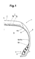
- the breaker 7 is composed of at least two crossed plies 7A and 7B of high modulus cords laid parallel with each other at an angle of from 10 to 35 degrees with respect to the tyre equator.
- the band is disposed on the radially outside of the breaker 7 and the cord angle with respect to the tyre equator is almost zero or a small angle of at most 10 degrees.
- the carcass 6 on the other hand, comprises at least one ply 9 of cords 10 arranged at an angle alpha of 75 to 90 degrees with respect to the tyre equator, and extending continuously between the bead portions 4 through the tread portion 2 and sidewall portions 3, and turned up around the bead core 5 in each bead portion from the axially inside to the axially outside so as to form a pair of turned up portions 6B and a main portion 6A therebetween.
- the carcass 6 may be composed of only the single ply 9. In this case, the ply 9A is defined by the main portion 6A. Further, the carcass 6 may be composed of two plies 9 both of which are turned up from the inside to the outside as explained above.
- an airtight layer is disposed along the inner surface HS of the tyre, covering the substantially entire surface HS.
- the airtight layer is defined by a rubber layer between the tyre inner surface HS and the innermost cords 10, namely, the carcass cords 10 of the ply 9A.
- the thickness T2 of the airtight layer measured from the tyre inner surface HS to the carcass cords 10 is decreased into a range of from 0.2 to 0.7 mm.
- the airtight layer is made of one or more kinds of air-impermeable rubber compounds, including a topping rubber 12 of the carcass ply 9A.
- the topping rubber 12 of the carcass ply 9A has a double layered structure comprising an inner topping rubber 12i made of an air-impermeable rubber compound 13, and an outer topping rubber 12o made of another kind of diene-base rubber 14 which is not air-impermeable.
- the boundary K between the inner topping rubber 12i and outer topping rubber 12o is preferably laid outside the innermost points of the carcass cords 10 as shown in Figs.2A and 2B. In these two examples, the boundary K reaches to the centre of the cords.
- the outer topping rubber 12o may be made of the same air-impermeable rubber compound 13 or a similar air-impermeable rubber compound.
- the boundary K may be laid inside the carcass cords 10.
- the air-impermeable rubber compound 13 which is used as carcass cord topping rubber includes, as its rubber base, 10 to 50 weight % of halogenated butyl rubber and/or halogenated isobutylene-paramethyl styrene copolymer, and 90 to 50 weight % of diene rubber so as to provide low air-permeability and strong adhesion to the cords 10 and another abutting rubber 14.
- the air-impermeable rubber compound 13 includes 45 to 60 parts by weight of carbon black with respect to 100 parts by weight of the rubber base.
- the diene rubber means natural rubber, butadiene rubber, styrenebutadiene rubber, isoprene rubber, chloroprene rubber, acrylonitrile butadiene rubber and the like, which may be used alone or in combination.
- chlorinated butyl rubber and/or brominated butyl rubber may be used.
- halogenated butyl rubber and halogenated isobutylene-paramethyl styrene copolymer are called "low-air-permeability rubber component(s)".
- the diene rubber is not less than 65 weight % and the total of the low-air-permeability rubber component(s) is not more than 35 weight %.
- the isobutylene content of the halogenated isobutylene-paramethyl styrene copolymer is in a range of from 89 to 97 weight %, more preferably 89 to 95 weight %, still more preferably 89 to 93 weight %.
- the above-mentioned carbon black preferably has
- the above-mentioned iodine adsorption number, specific surface area (nitrogen adsorption method), dibutyl phthalate adsorption number, and dibutyl phthalate adsorption number are measured according to the Japanese Industrial Standard K6217 - "Testing methods of fundamental characteristics of carbon black for rubber industry", Sections 6, 7, 9 and 10, respectively.
- the viscosity (Mooney viscosity) is increased to lessen the flow of rubber during vulcanising.
- the above-mentioned rubber thickness T2 measured from the tyre inner surface HS to the carcass cords 10 can be maintained stably in the above-mentioned range of from 0.2 to 0.7 mm.
- the iodine adsorption number is less than 80 mg/g or the specific surface area is less than 80 m2/g, then it is difficult to maintain the specific rubber thickness T2 because the unvulcanised rubber is provided with an excess liquidity or excess mobility. Further, the tensile strength and breaking strength of the vulcanised rubber tend to decrease.
- the hardness of the vulcanised rubber is liable to increase excessively to deteriorate ride comfort of the tyre.
- the dibutyl phthalate adsorption number is less than 70 ml/100g or the dibutyl phthalate adsorption number (compressed sample) is less than 70 ml/100g, then the tensile strength is liable to become insufficient.
- the dibutyl phthalate adsorption number is more than 100 ml/100g or the dibutyl phthalate adsorption number (compressed sample) is more than 90 ml/100g, then the unvulcanised rubber is increased in the viscosity and the processibility becomes worse. Further, the bending fatigue resistance of the vulcanised rubber decreases.
- a plasticiser such as phthalic acid derivatives, softener, e.g. mineral oil, aroma oil and the like is used to improve the processibility and plasticity.
- plasticiser may be used in this invention, but in this embodiment, in order to improve the adhesiveness of the air-impermeable rubber compound 13, a tackifier is added rather than plasticiser.
- a tackifier for such tackifier, coumarone resin, phenol resin, terpene resin, petroleum hydrocarbon resin, rosin derivatives may be used.
- the content of the tackifier is set in a range of from 1 to 10, preferably 3 to 10, more preferably 3 to 8 parts by weight with respect to 100 parts by weight of the rubber base.
- the airtight layer is the inner topping rubber 12i only, namely, the above-mentioned air-impermeable rubber compound 13.
- the airtight layer is made of the topping rubber 12i (or the above-mentioned air-impermeable rubber compound 13) and a second air-impermeable rubber compound 15 which forms an insulation rubber layer 17.
- the thickness T2 is decreased to near its lower limit of 0.2 mm, it is difficult to maintain such a small thickness stably without breaking partially.
- the green tyre is inflated to a high pressure using an inflatable bladder set inside the green tyre.
- the bladder is very likely to come into contact with the innermost cords 10. As a result, the airtight layer breaks at the contact point.
- the insulation rubber layer 17 can solve this problem.
- the insulation rubber layer 17 is made of the second air-impermeable rubber compound 15 as mentioned above.
- This compound 15 has ingredients which are similar to the above-mentioned ingredients of the air-impermeable rubber compound 13 but the content of the "low-air-permeability rubber component(s)" is increased, that is, the content thereof is set in a range of from 60 to 100 weight % and accordingly the remainder or the diene rubber is decreased into a range of 40 to 0 weight % so that the second air-impermeable rubber compound 15 is provided with fluidity, and the air-impermeable rubber compound 13 is provided with less fluidity during vulcanising the tyre.
- the ratio TQ1/T2 of a minimum torque TQ1 of the air-impermeable rubber compound 13 to a minimum torque TQ2 of the second air-impermeable rubber compound 15 is set in a range of not less than 1.1, and preferably at most 2.0.
- the minimum torque is obtained from the cure curve obtained under the following conditions according to the Japanese Industrial Standard K6300-"Physical testing methods for unvulcanised rubber", Section 8.4 "Die vulcanisation test-A method". That is, by oscillating a lower die, the torque transmitted from the lower die to an upper die through the specimen is measured. Conditions: Temperature of 170 deg.C; Angularly amplitude of plus/minus 1 degrees; and Oscillation of 100 cycles/minute.
- the thickness T3 of the air-impermeable rubber compound 13 measured from the innermost points of the cords 10 to the boundary between the topping rubber 12i and the insulation rubber layer 17 is set in a range of from 0.1 to 0.2 mm when the boundary K or the outward extent of the air-impermeable rubber compound 13 is not laid inside an envelope of the centres of the cords.
- the thickness T2 of the airtight layer as the total thickness of these two compounds 13 and 15 is set in the range of from 0.2 to 0.7 mm as mentioned above.
- Such a minimum torque difference TQ1-TQ2 may be provided by increasing the carbon content of the air-impermeable rubber compound 13 up to 10 weight % than the second air-impermeable rubber compound 15.
- the complex elastic modulus E*1 of the air-impermeable rubber compound 13 is not more than 5.5 MPa and the complex elastic modulus E*2 of the second air-impermeable rubber compound 15 is not more than 5.0 MPa.
- the complex elastic modulus is measured under the following conditions: Temperature of 70 deg.C; Frequency of 10 Hz; Initial strain of 10 %; and Dynamic distortion of plus/minus 1%.
- the complex elastic modulus E*1 is more than 5.5 MPa, then the rigidity is liable to increase excessively to decrease the resistance to bending fatigue. If the complex elastic modulus E*2 is more than 5.0 MPa, then the rigidity is liable to increase excessively to decrease the resistance to cracks.
- the pneumatic tyre is made as follows.
- a raw carcass ply material is wound around a tyre building drum into a cylindrical shape.
- Two bead cores are set on the raw carcass ply material on the drum.
- the raw carcass ply material is transformed from the cylindrical shape to a toroidal shape by expanding the tyre building drum while decreasing the distance between the bead cores (bead portions) as shown in Fig.3.
- Reinforcing cord layers such as the belt and rubber components such as sidewall rubber, bead clinch rubber, tread rubber, etc. are applied at appropriate times.
- the green tyre build as such is put in a mould, and an inflatable bladder is set inside the tyre. The bladder is inflated during heating of the green tyre.
- the above-mentioned raw carcass ply material 16 is made as follows.
- a lengthy cord fabric D is made, wherein carcass cords 10 are laid parallel with each other at a predetermined cord count in the widthwise direction thereof so as to extend along the longitudinal direction of the fabric and the cords 10 are rubberised with topping rubber 12.
- the cord fabric D is cut into pieces D1 according to the width La of the carcass ply material 16 and the carcass cord angle alpha with respect to the tyre equator.
- the inclination of the cutting line with respect to the longitudinal direction is alpha
- the spacing between the cutting lines in the longitudinal direction of the fabric D is equal to La x sin(alpha).
- the cut pieces D1 are spliced by overlapping the side edges De while aligning the cut edges, whereby a lengthy spliced cord fabric F in which carcass cords are embedded in parallel with each other at the angle alpha with respect to the longitudinal direction thereof is formed.
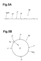
- the raw carcass ply material 16 is formed. (See Fig.5A)
- the raw carcass ply material 16 is wound around the tyre building drum and the ends Fe thereof are spliced to make it cylindrical. (See Fig.5B)
- the above-mentioned raw carcass ply material 16 may be used directly as shown in Fig.5A and 5B.
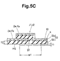
- Fig.5C shows the resultant splice joints (J1) between the side edges De and splice joint (J2) between the ends Fe.
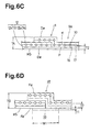
- Fig.2B where the airtight layer is made up of the topping rubber 12i and the insulation rubber layer 17, the insulation rubber layer 17 is applied to the inside of the lengthy spliced cord fabric F before cut into the raw carcass ply material 16.
- the raw carcass ply material 16 with the insulation rubber layer 17 shown in Fig.6A is wound around the tyre building drum and the ends Fe thereof are spliced to make it cylindrical as shown in Fig.6B.
- Fig.6C shows the resultant splice joints (J1) between the side edges De which are covered with the insulation rubber layer 17.
- Fig.6D shows the resultant splice joint (J2) between the ends Fe which is not covered.
- the airtight layer comes into contact with the bladder.
- mould lubricant is sprayed on the inner surface of the green tyre.
- the rubber patch 22 is an unvulcanised rubber tape whose thickness T1 is in a range of from 0.1 to 0.5 mm and width W1 is in a range of form 5 to 80 mm, preferably 25 to 50 mm.
- a rubber compound which is not air-impermeable may be used, but preferably an air-impermeable rubber compound is used which is the same as or similar to the air-impermeable rubber compound 13 or the second air-impermeable rubber compound 15 which is disposed as the innermost rubber layer and thus comes into contact with the patch.
- the use of the rubber patch 22 is effective in preventing the penetration.
- the patches to the joints (J1) may be applied in the state of a lengthy spliced cord fabric F in advance. But, in either case of Fig.5A and Fig.6A, an additional work to apply the patch to the joint (J2) is unavoidable.
- the rubber patch 22 is not used and also a mould lubricant or release agent is not applied to the tyre inner surface HS.
- the following release agent is applied to the surface of the bladder.
- a solution of an organic solvent such as gasoline and a combination of amide compound and silicon is used as the release agent.
- the solution is applied to the surface of the bladder and volatilised so that the surface is covered with a thin film.
- Fig.7 shows an alternative example of Fig.6A.
- the side edges De of the cut pieces D1 are butt jointed.
- the insulation rubber layer 17 will be function as a base to retain the butted state.
- Fig.8 shows an alternative example of Fig.5A.
- the side edges De of the cut pieces D1 are butt jointed.
- the above-mentioned rubber patch 22 is preferably utilised so that the cut pieces D1 retain the butted state.
- Table 1 and Table 2 show examples of rubber compounds and their characteristics.
- the definitions of or measuring methods for the characteristics are as follows.
- Mooney viscosity (ML1+4,130 deg.C) at a temperature of 130 deg.C was measured according to Japanese Industrial Standard K6300 - "Physical testing methods for unvulcanised rubber", Section 6 - "Mooney viscosity test”. The measured values are indicated by an index. The larger the index number, the higher the viscosity.
- Air permeability was measured according to the American Society for Testing Materials D1434-75M test method using a specimen vulcanised under a temperature of 170 deg.C. a pressure of 9.8 MPa and a curing time of 12 minutes. The smaller the value, the lower the air permeability.
- Flex crack resistance was measured according to the Japanese Industrial Standard K6260 - "Flex cracking test method for vulcanised rubber" except for the stroke of the reciprocal motion for causing bending strain.
- the length of the crack was measured after undergone bending deformation by 50% of the specified stroke 1,000,000 times and after undergone bending deformation by 70% of the specified stroke 300,000 times.
- the reciprocal of the length is indicated by an index. The larger the index number, the higher the flex crack resistance.
- a sheet of the concerned rubber compound and a typical sidewall rubber compound C1 shown in Table 3 (2 mm thickness, 80 mm width, 150 mm length) attached to each other were vulcanised under a pressure of 2 MPa, a temperature of 150 deg.C, a curing time of 30 min. And a peeling test at a speed of 50 mm/minute was made to obtain an adhesive strength. Under 50 kgf/25 mm is not acceptable.
- Table 4 shows results of comparison tests for tyre performance. Using the above-mentioned rubber compounds shown in Tables 1 and 2, pneumatic tyres of size 185/65R14 (wheel rim size 5.5JX14) having the structure shown in Fig.1 were made and tested for air leak and durability.
- the tyre mounted on its standard wheel rim was inflated to 300 kPa and then the pressure was measured after 90 days.
- the rate of decrease is indicated by an index. The larger the index number, the better the performance.
- the tyre mounted on its standard wheel rim and inflated to 190 kPa was run for 20,000 km under a tyre load of 5.0 kN at a speed of 80 km/hr.
- "ok" means there was no damage after running for the captioned distance.
- the number means a running distance in percentage of the captioned distance at which cracks or separation occurred.
- Table 5 shows results of further comparison tests for tyre performance.
- Pneumatic tyres of size 195/65R15 having the structure shown in Fig.1 were made using the rubber compounds shown in Table 6 and tested for air leak and durability.
- the tyre mounted on its standard wheel rim of size 5.5JX14 and inflated to 190 kPa was run under a tyre load of 6.96 kN at a speed of 70 km/hr until any damage occurred on the tyre outer surface and the running distance was measured.
- the running distance is indicated by an index. The larger the index number, the better the durability.
- Rubber compound C1 C2 Natural rubber 40 70 Butadiene rubber 60 -- Styrene butadiene rubber -- 30 Carbon black N550 60 -- N330 -- 50 Plasticiser Aroma oil 2 -- Mineral oil -- 10 Stearic acid 2 2 Hydrozincite 2.5 5 Insoluble sulfur 1.5 4 Accelerator 1 1 Carbon black in Tables 1 and 2 N219 N234 N326 N330 N550 N660 Iodine adsorption number (mg/g) 116 119 86 71 45 27 Specific surface area (nitrogen adsorption method)(m2/g) 112 121 83 76 42 31 Dibutyl phthalate adsorption number(ml/100g) 83 120 72 102 117 87 Dibutyl phthalate adsorption number (compressed sample) (ml/100g) 80 78 70 85 84 70 Rubber compound in Table 5 R1 R2 R2' R3 R4 R5 R2" Natural rubber 70 70 70 40 30 30 70 Styrene butadiene rubber 30 - - - -
Landscapes
- Engineering & Computer Science (AREA)
- Mechanical Engineering (AREA)
- Tires In General (AREA)
- Compositions Of Macromolecular Compounds (AREA)
- Yarns And Mechanical Finishing Of Yarns Or Ropes (AREA)
Abstract
Description

| Rubber compound | C1 | C2 |
| Natural rubber | 40 | 70 |
| Butadiene rubber | 60 | -- |
| Styrene butadiene rubber | -- | 30 |
| Carbon black | ||
| N550 | 60 | -- |
| N330 | -- | 50 |
| Plasticiser | ||
| Aroma oil | 2 | -- |
| Mineral oil | -- | 10 |
| Stearic acid | 2 | 2 |
| Hydrozincite | 2.5 | 5 |
| Insoluble sulfur | 1.5 | 4 |
| Accelerator | 1 | 1 |
| Carbon black in Tables 1 and 2 | N219 | N234 | N326 | N330 | N550 | N660 |
| Iodine adsorption number (mg/g) | 116 | 119 | 86 | 71 | 45 | 27 |
| Specific surface area (nitrogen adsorption method)(m2/g) | 112 | 121 | 83 | 76 | 42 | 31 |
| Dibutyl phthalate adsorption number(ml/100g) | 83 | 120 | 72 | 102 | 117 | 87 |
| Dibutyl phthalate adsorption number (compressed sample) (ml/100g) | 80 | 78 | 70 | 85 | 84 | 70 |


| Rubber compound in Table 5 | R1 | R2 | R2' | R3 | R4 | R5 | R2" |
| Natural rubber | 70 | 70 | 70 | 40 | 30 | 30 | 70 |
| Styrene butadiene rubber | 30 | - | - | - | - | - | - |
| EXXPRO90-10 () | - | - | - | - | - | - | 30 |
| Butylbromide | - | 30 | 30 | 60 | 70 | 70 | - |
| Carbon | 45HAF | 45HAF | 55HAF | 55HAF | 60GPF | 60HAF | 65HAF |
| Stearic acid | 2 | 2 | 2 | 2 | 1 | 1 | 2 |
| Tackifier | 0 | 5 | 5 | 5 | 5 | 5 | 5 |
| | 4 | 3.75 | 3.75 | 3.75 | 1 | 1 | 3.75 |
| Accelerator | 1 | 1 | 1 | 1 | 1 | 1 | 1 |
| | 5 | 5 | 5 | 5 | 4 | 4 | 5 |
| Plasticiser (oil) | 10 | 0 | 0 | 0 | 5 | 5 | 0 |
Claims (14)
- A pneumatic tyre comprising a tread portion (2), a pair of sidewall portions (3), a pair of bead portions (4), a carcass (6) comprising a ply (9) of cords (10) defining the innermost reinforcing cord layer extending between the bead portions (4), an airtight layer disposed inside said cords of the carcass ply along the inner surface of the tyre, covering the substantially entire inner surface of the tyre, characterised in that the airtight layer is made of air-impermeable rubber including at least 10 weight % of halogenated butyl rubber and/or halogenated isobutylene-paramethyl styrene copolymer in its rubber base, and the thickness (T2) of the airtight layer measured from the inner surface of the tyre to the cords (10) of the carcass ply is in a range of from 0.2 to 0.7 mm.
- A pneumatic tyre according to claim 1, characterised in that the airtight layer is made of one kind of air-impermeable rubber compound comprising 100 parts by weight of rubber base and 45 to 60 parts by weight of carbon black, said rubber base comprising 10 to 50 weight % of halogenated butyl rubber and/or halogenated isobutylene-paramethyl styrene copolymer and 50 to 90 weight % of diene rubber, the carbon black having the following parameters (1) and (2):(1) an iodine adsorption number of from 80 to 125 mg/g or a specific surface area (nitrogen adsorption method) of from 80 to 120 m2/g,(2) a dibutyl phthalate adsorption number of from 70 to 100 ml/100g or a dibutyl phthalate adsorption number (compressed sample) of 70 to 90 ml/100g.
- A pneumatic tyre according to claim 1, characterised in that the airtight layer is made of a first air-impermeable rubber compound and a second air-impermeable rubber compound, the first air-impermeable rubber compound forms an outer layer (12o) coming into contact with the cords (10), and the first air-impermeable rubber compound comprises 10 to 50 weight % of halogenated butyl rubber and/or halogenated isobutylene-paramethyl styrene copolymer and 90 to 50 weight % of diene rubber in its rubber base, the second air-impermeable rubber compound forms an inner layer (12i) defining the tyre inner surface, and the second air-impermeable rubber compound comprises 60 to 100 weight % of halogenated butyl rubber and/or halogenated isobutylene-paramethyl styrene copolymer and 40 to 0 weight % of diene rubber in its rubber base, a minimum torque of the first air-impermeable rubber compound is at least 1.1 times a minimum torque of the second air-impermeable rubber compound, wherein the minimum torque is measured under a temperature of 170 deg.C, an angularly amplitude of plus/minus 1 degrees, and an oscillation of 100 cycles/minute.
- A pneumatic tyre according to claim 3, characterised in that the thickness of the first air-impermeable rubber compound forming the outer layer (12o) measured form the innermost points of the carcass cords to the inner surface of the outer layer is in a range of from 0.1 to 0.2 mm.
- A pneumatic tyre according to claim 3 or 4, characterised in that the complex elastic modulus E*1 of the first air-impermeable rubber compound is not more than 5.5 MPa, and the complex elastic modulus E*2 of the second air-impermeable rubber compound is not more than 5.0 MPa.
- A pneumatic tyre according to claim 3 or 4, characterised in that the complex elastic modulus E*1 of the first air-impermeable rubber compound is not more than 5.5 MPa, and the complex elastic modulus E*2 of the second air-impermeable rubber compound is not more than 5.0 MPa and smaller than the complex elastic modulus E*1.
- A pneumatic tyre according to claim 2, characterised in that said one kind of air-impermeable rubber compound is a topping rubber for said cords (10) of the carcass ply which covers at least the inside of the carcass ply.
- A pneumatic tyre according to claim 3, characterised in that said first air-impermeable rubber compound is a topping rubber for said cords (10) of the carcass ply which covers at least the inside of the carcass ply.
- A pneumatic tyre according to claim 7, characterised in that the outside of the carcass ply (6) is covered with a topping rubber compound different from said one kind of air-impermeable rubber compound.
- A pneumatic tyre according to claim 8, characterised in that the outside of the carcass ply (6) is covered with a topping rubber compound different from said first air-impermeable rubber compound.
- A pneumatic tyre according to any of claims 1 to 10, characterised in that said carcass ply has a joint covered with a thin rubber patch disposed on the tyre inner surface.
- A pneumatic tyre according to any of claims 1 to 10, characterised in that said carcass ply has a joint exposed on the tyre inner surface.
- A pneumatic tyre according to any of claims 1 to 10, characterised in that said carcass ply has a joint covered with a thin rubber patch disposed on the tyre inner surface, and a mould release agent is applied to the tyre inner surface.
- A pneumatic tyre according to any of claims 1 to 10, characterised in that said carcass ply has a joint exposed on the tyre inner surface, and a mould release agent is not applied to the tyre inner surface.
Applications Claiming Priority (10)
| Application Number | Priority Date | Filing Date | Title |
|---|---|---|---|
| JP2000303909 | 2000-10-03 | ||
| JP2000303907A JP2002103907A (en) | 2000-10-03 | 2000-10-03 | Pneumatic tire |
| JP2000303908A JP3588319B2 (en) | 2000-10-03 | 2000-10-03 | Pneumatic tire |
| JP2000303908 | 2000-10-03 | ||
| JP2000303906A JP4138223B2 (en) | 2000-10-03 | 2000-10-03 | Pneumatic tire |
| JP2000303910A JP3393853B2 (en) | 2000-10-03 | 2000-10-03 | Pneumatic tire |
| JP2000303906 | 2000-10-03 | ||
| JP2000303909A JP3393852B2 (en) | 2000-10-03 | 2000-10-03 | Pneumatic tire and ply used for it |
| JP2000303910 | 2000-10-03 | ||
| JP2000303907 | 2000-10-03 |
Publications (2)
| Publication Number | Publication Date |
|---|---|
| EP1195270A2 true EP1195270A2 (en) | 2002-04-10 |
| EP1195270A3 EP1195270A3 (en) | 2003-04-09 |
Family
ID=27531670
Family Applications (1)
| Application Number | Title | Priority Date | Filing Date |
|---|---|---|---|
| EP01308434A Withdrawn EP1195270A3 (en) | 2000-10-03 | 2001-10-02 | Pneumatic tyre |
Country Status (2)
| Country | Link |
|---|---|
| US (1) | US6814118B2 (en) |
| EP (1) | EP1195270A3 (en) |
Cited By (1)
| Publication number | Priority date | Publication date | Assignee | Title |
|---|---|---|---|---|
| EP1433622A1 (en) * | 2002-12-24 | 2004-06-30 | Sumitomo Rubber Industries Ltd. | Pneumatic radial tire |
Families Citing this family (19)
| Publication number | Priority date | Publication date | Assignee | Title |
|---|---|---|---|---|
| US20040154727A1 (en) * | 2003-02-11 | 2004-08-12 | Weissert James Thomas | Method and apparatus for manufacturing carcass plies for a tire |
| JP4113850B2 (en) * | 2004-03-17 | 2008-07-09 | 住友ゴム工業株式会社 | Rubber composition for tire and run flat tire obtained using the same |
| CA2517822C (en) * | 2004-09-06 | 2009-10-27 | Honda Motor Co., Ltd. | Seat mount structure for saddle ride vehicle |
| WO2007019561A1 (en) * | 2005-08-09 | 2007-02-15 | Arizona Chemical Company | Rubber compositions containing improved tackifiers |
| EP2502742B1 (en) | 2005-10-27 | 2017-06-21 | ExxonMobil Chemical Patents Inc. | Construction comprising tie layer for pneumatic tire |
| RU2379187C1 (en) * | 2005-10-27 | 2010-01-20 | Эксонмобил Кемикал Пэйтентс, Инк. | Structure with joining layer |
| WO2007050061A1 (en) * | 2005-10-27 | 2007-05-03 | Exxonmobil Chemical Patents Inc. | Construction comprising tie layer |
| JP4725416B2 (en) * | 2006-05-26 | 2011-07-13 | 横浜ゴム株式会社 | Pneumatic tire manufacturing method |
| US8846792B2 (en) | 2006-10-26 | 2014-09-30 | The Yokohama Rubber Co., Ltd. | Construction comprising tie layer |
| WO2008051253A1 (en) | 2006-10-26 | 2008-05-02 | Exxonmobil Chemical Patents Inc. | Low moisture permeability laminate construction |
| US8082715B2 (en) * | 2007-04-30 | 2011-12-27 | Fireline 520, Llc | Bottom mount fire barrier systems including fire barrier/retainer structures and installation tools |
| US8776851B2 (en) | 2008-08-29 | 2014-07-15 | The Goodyear Tire & Rubber Company | Film to keep tire surface clean and simultaneously prime for better adhesion of balance pad |
| JP5247852B2 (en) | 2010-11-05 | 2013-07-24 | 住友ゴム工業株式会社 | Pneumatic tire manufacturing method |
| JP5225431B2 (en) * | 2010-12-06 | 2013-07-03 | 住友ゴム工業株式会社 | Strip, method for producing the same, and method for producing a pneumatic tire |
| RU2487016C2 (en) * | 2011-09-06 | 2013-07-10 | Общество с ограниченной ответственностью "Холдинговая Компания "ЛОйл НЕФТЕХИМ" | Pneumatic tire and method of its production |
| JP5349630B2 (en) * | 2012-02-06 | 2013-11-20 | 住友ゴム工業株式会社 | Pneumatic tire |
| IN2015DN02472A (en) | 2012-09-06 | 2015-09-04 | Exxonmobil Chem Patents Inc | |
| CN111732792B (en) * | 2020-07-14 | 2023-01-31 | 四川远星橡胶有限责任公司 | Sizing material for airtight layer of run-flat tire and preparation method thereof |
| KR102788811B1 (en) * | 2023-02-01 | 2025-04-01 | 한국타이어앤테크놀로지 주식회사 | A pneumatic tire with multiple steel chafer toppings |
Family Cites Families (3)
| Publication number | Priority date | Publication date | Assignee | Title |
|---|---|---|---|---|
| JP2962658B2 (en) * | 1994-08-22 | 1999-10-12 | 住友ゴム工業株式会社 | Pneumatic tubeless tire |
| JP3667017B2 (en) * | 1997-01-10 | 2005-07-06 | 横浜ゴム株式会社 | Pneumatic tire |
| JP3681246B2 (en) * | 1997-01-10 | 2005-08-10 | 横浜ゴム株式会社 | Pneumatic tire |
-
2001
- 2001-10-02 EP EP01308434A patent/EP1195270A3/en not_active Withdrawn
- 2001-10-02 US US09/968,542 patent/US6814118B2/en not_active Expired - Fee Related
Cited By (2)
| Publication number | Priority date | Publication date | Assignee | Title |
|---|---|---|---|---|
| EP1433622A1 (en) * | 2002-12-24 | 2004-06-30 | Sumitomo Rubber Industries Ltd. | Pneumatic radial tire |
| US6883572B2 (en) | 2002-12-24 | 2005-04-26 | Sumitomo Rubber Industries, Ltd. | Pneumatic radial tire with inner carcass ply E*1 different from outer carcass ply E*2 |
Also Published As
| Publication number | Publication date |
|---|---|
| EP1195270A3 (en) | 2003-04-09 |
| US6814118B2 (en) | 2004-11-09 |
| US20020066512A1 (en) | 2002-06-06 |
Similar Documents
| Publication | Publication Date | Title |
|---|---|---|
| EP1195270A2 (en) | Pneumatic tyre | |
| CN102574423B (en) | Tires comprising carcass reinforcing cords of low permeability and rubber compounds of variable thickness | |
| CN102216091B (en) | Tires comprising carcass reinforcing cables of low permeability and rubber compounds of reduced thickness | |
| CN1962291B (en) | Pneumatic tire and method for producing the same, and cushion rubber for the tire | |
| AU752115B2 (en) | Pneumatic tire | |
| EP2355986B1 (en) | Pneumatic vehicle tire | |
| EP0924108B1 (en) | Heavy duty pneumatic radial tires | |
| CA2086638C (en) | Pneumatic tire | |
| EP0842795A2 (en) | Pneumatic tyre | |
| CN102257210A (en) | Tyre having low-permeability carcass reinforcement cables, and textile cords associated with the carcass reinforcement | |
| EP3885167A1 (en) | Tire | |
| US6736178B2 (en) | Pneumatic tire with specified bead portion | |
| AU677169B2 (en) | Tubeless tyre beads and methods for manufacturing same | |
| CN102753336B (en) | Manufacturing method of pneumatic tire | |
| US5746860A (en) | Method of building green tires for low-section profile pneumatic radial tires | |
| CA2227705C (en) | Abrasion-resistant elastomeric member of a tire-building drum | |
| EP0810105B1 (en) | Pneumatic radial tires provided with a side portion reinforcing layer | |
| JPH0550807A (en) | Pneumatic tire | |
| EP3366496B1 (en) | Run flat tire and method for manufacturing same | |
| EP3421262B1 (en) | Run flat tire and method for manufacturing same | |
| EP1072444B1 (en) | Heavy duty radial tire | |
| EP0475733A2 (en) | Tubeless pneumatic tyres | |
| JP4928107B2 (en) | Run flat tire | |
| US20180244113A1 (en) | Run flat tire and method for manufacturing same | |
| PL179190B1 (en) | Non-vulcanized carcass, especially as a semi-finished product for the production of radial, spacer pneumatic tire PL PL |
Legal Events
| Date | Code | Title | Description |
|---|---|---|---|
| PUAI | Public reference made under article 153(3) epc to a published international application that has entered the european phase |
Free format text: ORIGINAL CODE: 0009012 |
|
| AK | Designated contracting states |
Kind code of ref document: A2 Designated state(s): AT BE CH CY DE DK ES FI FR GB GR IE IT LI LU MC NL PT SE TR |
|
| AX | Request for extension of the european patent |
Free format text: AL;LT;LV;MK;RO;SI |
|
| PUAL | Search report despatched |
Free format text: ORIGINAL CODE: 0009013 |
|
| AK | Designated contracting states |
Kind code of ref document: A3 Designated state(s): AT BE CH CY DE DK ES FI FR GB GR IE IT LI LU MC NL PT SE TR Designated state(s): AT BE CH CY DE DK ES FI FR GB GR IE IT LI LU MC NL PT SE TR |
|
| AX | Request for extension of the european patent |
Extension state: AL LT LV MK RO SI |
|
| 17P | Request for examination filed |
Effective date: 20031001 |
|
| AKX | Designation fees paid |
Designated state(s): DE FR GB |
|
| 17Q | First examination report despatched |
Effective date: 20060626 |
|
| GRAP | Despatch of communication of intention to grant a patent |
Free format text: ORIGINAL CODE: EPIDOSNIGR1 |
|
| STAA | Information on the status of an ep patent application or granted ep patent |
Free format text: STATUS: THE APPLICATION IS DEEMED TO BE WITHDRAWN |
|
| 18D | Application deemed to be withdrawn |
Effective date: 20090323 |