EP1195207A2 - Turret punch press - Google Patents
Turret punch press Download PDFInfo
- Publication number
- EP1195207A2 EP1195207A2 EP01123590A EP01123590A EP1195207A2 EP 1195207 A2 EP1195207 A2 EP 1195207A2 EP 01123590 A EP01123590 A EP 01123590A EP 01123590 A EP01123590 A EP 01123590A EP 1195207 A2 EP1195207 A2 EP 1195207A2
- Authority
- EP
- European Patent Office
- Prior art keywords
- work sheet
- punch
- turret
- employed
- lower turret
- Prior art date
- Legal status (The legal status is an assumption and is not a legal conclusion. Google has not performed a legal analysis and makes no representation as to the accuracy of the status listed.)
- Granted
Links
- 239000000463 material Substances 0.000 claims abstract description 25
- 238000007599 discharging Methods 0.000 claims abstract description 10
- 230000003028 elevating effect Effects 0.000 description 4
- 239000012530 fluid Substances 0.000 description 2
- 238000012840 feeding operation Methods 0.000 description 1
- 238000000034 method Methods 0.000 description 1
Images



Classifications
-
- B—PERFORMING OPERATIONS; TRANSPORTING
- B21—MECHANICAL METAL-WORKING WITHOUT ESSENTIALLY REMOVING MATERIAL; PUNCHING METAL
- B21D—WORKING OR PROCESSING OF SHEET METAL OR METAL TUBES, RODS OR PROFILES WITHOUT ESSENTIALLY REMOVING MATERIAL; PUNCHING METAL
- B21D45/00—Ejecting or stripping-off devices arranged in machines or tools dealt with in this subclass
- B21D45/003—Ejecting or stripping-off devices arranged in machines or tools dealt with in this subclass in punching machines or punching tools
-
- B—PERFORMING OPERATIONS; TRANSPORTING
- B21—MECHANICAL METAL-WORKING WITHOUT ESSENTIALLY REMOVING MATERIAL; PUNCHING METAL
- B21D—WORKING OR PROCESSING OF SHEET METAL OR METAL TUBES, RODS OR PROFILES WITHOUT ESSENTIALLY REMOVING MATERIAL; PUNCHING METAL
- B21D28/00—Shaping by press-cutting; Perforating
- B21D28/02—Punching blanks or articles with or without obtaining scrap; Notching
- B21D28/12—Punching using rotatable carriers
-
- Y—GENERAL TAGGING OF NEW TECHNOLOGICAL DEVELOPMENTS; GENERAL TAGGING OF CROSS-SECTIONAL TECHNOLOGIES SPANNING OVER SEVERAL SECTIONS OF THE IPC; TECHNICAL SUBJECTS COVERED BY FORMER USPC CROSS-REFERENCE ART COLLECTIONS [XRACs] AND DIGESTS
- Y10—TECHNICAL SUBJECTS COVERED BY FORMER USPC
- Y10T—TECHNICAL SUBJECTS COVERED BY FORMER US CLASSIFICATION
- Y10T83/00—Cutting
- Y10T83/202—With product handling means
- Y10T83/2092—Means to move, guide, or permit free fall or flight of product
- Y10T83/2198—Tiltable or withdrawable support
-
- Y—GENERAL TAGGING OF NEW TECHNOLOGICAL DEVELOPMENTS; GENERAL TAGGING OF CROSS-SECTIONAL TECHNOLOGIES SPANNING OVER SEVERAL SECTIONS OF THE IPC; TECHNICAL SUBJECTS COVERED BY FORMER USPC CROSS-REFERENCE ART COLLECTIONS [XRACs] AND DIGESTS
- Y10—TECHNICAL SUBJECTS COVERED BY FORMER USPC
- Y10T—TECHNICAL SUBJECTS COVERED BY FORMER US CLASSIFICATION
- Y10T83/00—Cutting
- Y10T83/202—With product handling means
- Y10T83/2092—Means to move, guide, or permit free fall or flight of product
- Y10T83/2209—Guide
- Y10T83/2213—Product-diverting conduit in or from hollow tool
-
- Y—GENERAL TAGGING OF NEW TECHNOLOGICAL DEVELOPMENTS; GENERAL TAGGING OF CROSS-SECTIONAL TECHNOLOGIES SPANNING OVER SEVERAL SECTIONS OF THE IPC; TECHNICAL SUBJECTS COVERED BY FORMER USPC CROSS-REFERENCE ART COLLECTIONS [XRACs] AND DIGESTS
- Y10—TECHNICAL SUBJECTS COVERED BY FORMER USPC
- Y10T—TECHNICAL SUBJECTS COVERED BY FORMER US CLASSIFICATION
- Y10T83/00—Cutting
- Y10T83/202—With product handling means
- Y10T83/2092—Means to move, guide, or permit free fall or flight of product
- Y10T83/2209—Guide
- Y10T83/2216—Inclined conduit, chute or plane
-
- Y—GENERAL TAGGING OF NEW TECHNOLOGICAL DEVELOPMENTS; GENERAL TAGGING OF CROSS-SECTIONAL TECHNOLOGIES SPANNING OVER SEVERAL SECTIONS OF THE IPC; TECHNICAL SUBJECTS COVERED BY FORMER USPC CROSS-REFERENCE ART COLLECTIONS [XRACs] AND DIGESTS
- Y10—TECHNICAL SUBJECTS COVERED BY FORMER USPC
- Y10T—TECHNICAL SUBJECTS COVERED BY FORMER US CLASSIFICATION
- Y10T83/00—Cutting
- Y10T83/869—Means to drive or to guide tool
- Y10T83/8727—Plural tools selectively engageable with single drive
- Y10T83/8732—Turret of tools
-
- Y—GENERAL TAGGING OF NEW TECHNOLOGICAL DEVELOPMENTS; GENERAL TAGGING OF CROSS-SECTIONAL TECHNOLOGIES SPANNING OVER SEVERAL SECTIONS OF THE IPC; TECHNICAL SUBJECTS COVERED BY FORMER USPC CROSS-REFERENCE ART COLLECTIONS [XRACs] AND DIGESTS
- Y10—TECHNICAL SUBJECTS COVERED BY FORMER USPC
- Y10T—TECHNICAL SUBJECTS COVERED BY FORMER US CLASSIFICATION
- Y10T83/00—Cutting
- Y10T83/869—Means to drive or to guide tool
- Y10T83/8742—Tool pair positionable as a unit
Definitions
- the present invention relates to a turret punch press and especially to the discharging structure of a small article work sheet after the cutting off processing.
- the cutting off operation of the connected part is carried out by a subhead of which is a punch processing head exclusive for the cutting off operation, employed at a position apart from the turret.
- the discharging of the cut off product work sheet is generally carried out by a suction typed unloader. Since the small article cannot be sucked, the work shooter to be mentioned in the following is to be used.
- the work shooter is leading to the outside of the machine from the opening near the subhead in the upper surface of the table. The opening is closed during the processing.
- the subhead Since the subhead is required to be located at a position apart from the turret, the subhead is to be located greatly off set from the main punch head provided in the designated position over the turret. As a result, it is difficult to obtain processing precision, the cutting off processing of the connected part of the product work sheet and the material work sheet cannot be carried out neatly, thus there are cases in which the quality of the product is influenced. Moreover, since the subhead is provided with the punch driving mechanism, by providing a subhead, the structure of the turret punch press becomes complicated and the cost is increased.
- the object of the present invention is to provide a turret punch press capable of solving such problems, and capable of discharging easily the small article work sheet cut off from the material work sheet, without employing a separate subhead from a punch driving mechanism.
- the turret punch press comprises an upper turret holding a plurality of punch tools, a lower turret holding in a plurality the die tools corresponding to the punch tools, and a punch driving mechanism for driving the punch tool of the upper turret.
- the work sheet outlet for discharging the small article work sheet cut off from the material work sheet in the punch processing is employed.
- the work sheet outlet is provided in the lower turret, even when the cutting off processing is carried out with the punch tool of the upper turret by the punch driving mechanism, the cut off small article work sheet is discharged from the work sheet outlet of the lower turret in that form. Therefore, there is no need to employ a driving mechanism of the subhead or the like exclusive for the cutting off, apart from the punch driving mechanism. As a result, the structure of the punch press is simplified and the cost can be reduced.
- a shooter connected to the work sheet outlet of the lower turret can be provided in the main body frame supporting the lower turret. If constructed likewise, the small article work sheet cut off from the material work sheet can be discharged easily to the outside of the machine by being slid over the shooter.
- an opening and closing plate freely opening and closing to cover the work sheet outlet can be provided in the lower turret so that the upper surface level in the closed state is to be approximately equal to the upper surface level of the lower turret.
- the opening and closing plate can be used just as a cover, or can be used as a shooter, to discharge the small article work sheet being slid in self-control.
- the upper surface level of the lower turret mentioned here is the upper surface of the table when employing a table in the lower turret.
- a turret punch press comprises an upper turret 3 and a lower turret 4 of the same shaft employed rotatable in between an upper frame section 1a and a lower frame section 1b of a main body frame 1, and a punch driving mechanism 5.
- the upper turret 3 and the lower turret 4 are selected and rotated by the selecting driving mechanism (not shown in the drawings).
- a plurality of punch storing holes 8 which hold the punch tool 6 freely elevating and descending, are employed by being arranged on the circumference of the upper turret 3.
- the punch storing holes 8 are employed in two lines inside and outside.
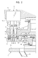
- the punch tool 6 is a punch cutting blade 7 (refer to Figure 2) employed within the punch holder.
- the lower turret 4 is a die tool 9 corresponding to the punch tool 6 of the upper turret 3, held in a plurality via a die holder 10, and a plurality of die holders 10 are employed by being arranged on the circumference as shown in Figure 3.
- the punch driving mechanism 5 drives the punch tool 6 of the upper turret 3 by elevating and descending a ram 11.
- the ram 11 is connected to the drive source (not shown in the drawings) of the motor or the hydraulic cylinder or the like.
- the drive source not shown in the drawings
- the punch tool 6 includes a letter "T" shaped head 6a in its upper edge, and is supported not to fall off from the upper turret 3 by the head 6a being guided by a ring shaped guide plate (not shown in the drawings). In the place of the guide plate, a spring mechanism (not shown in the drawings) which supports the punch tool 6 at an elevating position, can be employed.
- the punch tool 6 of which has reached the plane position (punch position) where the ram 11 is employed, is to be connected to the ram 11 by the head 6a engaging with the letter "T" shaped groove at the lower edge of the individual ram 11a.
- the upper surface level of the opening and closing plate 14 in the closed state is set to be approximately equal to a table 17 employed in the upper surface of the lower turret 4 or a table 15 employed in the upper surface of the die holder 10.
- the tables 15, 17 are employed at the same level as to the upper surface level of a table 16 employed in the front of the lower turret 4.
- the inner edge section of the opening and closing plate 14 which is located in the inner diameter side of the lower turret 4, is supported freely opening and closing in the opening edge of the work sheet outlet 12 via a supporting shaft 18. Moreover, the opening and closing plate 14 is connected to an opening and closing drive source 19.
- the opening and closing drive source 19 comprises the fluid pressured cylinder, and the intermediate part of the lower surface of the opening and closing plate 14 is connected to a piston rod 19a via a link 20.
- the opening and closing plate 14 carries out opening and closing operation by being driven to elevate and descend by the opening and closing drive source 19 comprised of the fluid pressured cylinder.
- a work sheet feeding mechanism (not shown in the drawings) for feeding to front and back, and to left and right, by gripping the material work sheet transported onto the table 16, is employed.
- the work sheet feeding mechanism feeds to the punch position, the parts to be processed of the material work sheet.
- the operation of the structure illustrated above will now be described.
- the upper turret 3 and the lower turret 4 are selected and rotated in synchronism, and the requested punch tool 6 and the corresponding die tool 9 are selected to the punch position.
- the selecting of the individual ram 11a is carried out by a ram selector 21.
- the feeding of the material work sheet is carried out by the work sheet feeding mechanism, and the part to be processed of the material work sheet is to be positioned on the selected die tool 9. Under this condition, the ram 11 of the punch driving mechanism 5 are driven to elevate and descend and the punch processing is carried out.
- a continuous punch processing is carried out by shifting the punch position accordingly by the feeding of the material work sheet. Then, the punch processing is carried out to the entire outer circumference of the product work sheet.
- This punch processing can be processed to leave a part of the outer circumference of the product work sheet as a connected section and to cut off the connected part by the punch processing later on, or can be a punch processing continued to the entire circumference.
- the die tool 9 of the lower turret 4 wherein the work sheet outlet 12 is located in the inner diameter side, and the punch tool 6 of the corresponding upper turret 3 are used, and a small article work sheet W is cut off from the material work sheet by punch processing as shown in Figure 4A.
- the work sheet outlet 12 of the lower turret 4 is covered by the opening and closing plate 14 during the punch processing.
- the upper surface level of the opening and closing plate 14 is set to equal approximately with the upper surface level of the table 15 of the upper surface of the die holder 10 and the table 17 of the inner diameter side of the lower turret 4. Therefore, the work sheet outlet 12 does not interfere with the feeding of the material work sheet and the transferring of the work sheet can be carried out smoothly.
- the opening and closing drive source 19 drives to the descending side, the opening and closing plate 14 becomes into a released state, facing perpendicularly downward, and the work sheet outlet 12 opens.
- the small article work sheet W falls freely from the work sheet outlet 12 of the lower turret 4 to the shooter 13, slides over the shooter 13, and is discharged to the outside of the machine.
- the work sheet outlet 12 for discharging the small article work sheet W is employed in the lower turret 4. Therefore, without employing a subhead separately from the punch driving mechanism 5, the small article work sheet W can be cut off from the material work sheet only by the punch driving mechanism 5, and can easily be discharged from the work sheet outlet 12 to outside of the punch position.
- the turret punch press comprises an upper turret for supporting a plurality of punch tools, a lower turret for supporting a plurality of die tools corresponding to the punch tool, and a punch driving mechanism for driving the punch tool of the upper turret. Since a work sheet outlet is employed in the lower turret to discharge the small article work sheet cut off from the material work sheet in the punch processing, without employing a processing head exclusive for the cutting off processing, the small article work sheet can be cut off from the material work sheet only by the punch driving mechanism, and easily discharged from the work sheet outlet.
- the small article work sheet cut off from the material work sheet can be discharged to the outside of the machine easily by self-control.
- an opening and closing plate for covering the work sheet outlet When an opening and closing plate for covering the work sheet outlet is employed freely opening and closing to the lower part in the lower turret, the work sheet feeding or the punch processing can be prevented from being interrupted by the work sheet outlet. Moreover, the opening and closing plate can be used as a shooter and the small article work sheet can be discharged by being slid.
Landscapes
- Engineering & Computer Science (AREA)
- Mechanical Engineering (AREA)
- Punching Or Piercing (AREA)
- Perforating, Stamping-Out Or Severing By Means Other Than Cutting (AREA)
Abstract
Description
Claims (3)
- A turret punch press comprising:wherein a work sheet outlet for discharging a small article work sheet cut off from a material work sheet in the punch processing, is employed in said lower turret.an upper turret for supporting a plurality of punch tools;a lower turret for supporting a plurality of die tools corresponding to the punch tools; anda punch driving mechanism for driving the punch tools of the upper turret;
- A turret punch press according to claim 1 wherein a shooter connected to the work sheet outlet of said lower turret is employed in the main body frame for supporting said lower turret.
- A turret punch press according to claim 1 or claim 2 wherein an opening and closing plate, freely opening and closing, for covering said work sheet outlet, is employed in said lower turret so that the upper surface level in the closed state is to become approximately equal to the upper surface level of said lower turret.
Applications Claiming Priority (2)
| Application Number | Priority Date | Filing Date | Title |
|---|---|---|---|
| JP2000304346 | 2000-10-04 | ||
| JP2000304346A JP3700569B2 (en) | 2000-10-04 | 2000-10-04 | Turret punch press |
Publications (3)
| Publication Number | Publication Date |
|---|---|
| EP1195207A2 true EP1195207A2 (en) | 2002-04-10 |
| EP1195207A3 EP1195207A3 (en) | 2003-08-13 |
| EP1195207B1 EP1195207B1 (en) | 2006-05-10 |
Family
ID=18785409
Family Applications (1)
| Application Number | Title | Priority Date | Filing Date |
|---|---|---|---|
| EP01123590A Expired - Lifetime EP1195207B1 (en) | 2000-10-04 | 2001-10-01 | Turret punch press |
Country Status (4)
| Country | Link |
|---|---|
| US (1) | US6988436B2 (en) |
| EP (1) | EP1195207B1 (en) |
| JP (1) | JP3700569B2 (en) |
| DE (1) | DE60119465T2 (en) |
Cited By (2)
| Publication number | Priority date | Publication date | Assignee | Title |
|---|---|---|---|---|
| EP2177289A1 (en) * | 2008-10-20 | 2010-04-21 | Trumpf Werkzeugmaschinen GmbH + Co. KG | Machine tools and method for discharging a workpiece part |
| FR2990886A1 (en) * | 2012-05-24 | 2013-11-29 | Peugeot Citroen Automobiles Sa | Method for manufacturing sheet part for car, involves forming embossing in chute by stamping sheet part during deformation step, where embossing is projected towards evacuation slope to limit contact surface of chute against slope |
Families Citing this family (5)
| Publication number | Priority date | Publication date | Assignee | Title |
|---|---|---|---|---|
| DE202008003915U1 (en) * | 2008-03-19 | 2008-05-29 | Trumpf Werkzeugmaschinen Gmbh + Co. Kg | Eject tool for machining workpieces |
| JP2009248161A (en) * | 2008-04-09 | 2009-10-29 | Metalart Corp | Workpiece transfer device |
| WO2011074556A1 (en) * | 2009-12-18 | 2011-06-23 | 株式会社 アマダ | Punch press |
| CN105070542B (en) * | 2015-08-12 | 2018-06-26 | 黄俊龙 | For the punching press tooling of capacitor case |
| KR102495105B1 (en) * | 2022-11-04 | 2023-02-06 | 안혁 | Punching mold with scrap suction function |
Family Cites Families (17)
| Publication number | Priority date | Publication date | Assignee | Title |
|---|---|---|---|---|
| US1448069A (en) * | 1919-12-19 | 1923-03-13 | United Shoe Machinery Corp | Method of and machine for compressing boot and shoe parts |
| US3685380A (en) * | 1971-02-19 | 1972-08-22 | Amada Ltd Us | Multi-track turret and overload protection |
| US3777601A (en) * | 1971-03-29 | 1973-12-11 | P Strandell | Punching apparatus |
| CA987228A (en) * | 1972-12-21 | 1976-04-13 | Joseph Marconi | Blanking die with shuttle plate support |
| US3839935A (en) * | 1973-01-15 | 1974-10-08 | Amada Ltd | Blank punching apparatus |
| US4085639A (en) * | 1975-04-03 | 1978-04-25 | Joseph Marconi | Blanking die and holder construction for punch presses |
| US3961549A (en) * | 1975-06-16 | 1976-06-08 | Houdaille Industries, Inc. | Die changing turret table segment |
| JPS55161530A (en) * | 1979-06-02 | 1980-12-16 | Yamazaki Mazak Corp | Turret punch press furnished with plural hammers |
| JPS6343730A (en) * | 1986-08-09 | 1988-02-24 | Murata Mach Ltd | Punching method and punching device |
| JPH02224828A (en) * | 1989-02-28 | 1990-09-06 | Amada Co Ltd | Combined machine of punching and laser beam machining |
| US4986153A (en) * | 1989-09-05 | 1991-01-22 | Strippit Inc. | Method and apparatus for the parting and removal of pieces from punch presses |
| JP2918121B2 (en) * | 1989-10-20 | 1999-07-12 | 株式会社アマダ | Punch press |
| JP2926447B2 (en) | 1990-05-11 | 1999-07-28 | 鈴木総業株式会社 | Aquatic organism adhesion prevention material |
| JPH0829371B2 (en) * | 1990-05-14 | 1996-03-27 | 株式会社小松製作所 | Multi-tasking machine |
| JPH0443416A (en) | 1990-06-08 | 1992-02-13 | Brother Ind Ltd | Electronic equipment |
| DE4129556A1 (en) * | 1991-09-05 | 1993-03-11 | Amada Co | REVOLVER HEAD PUNCHING PRESS |
| JP2001300646A (en) * | 2000-04-20 | 2001-10-30 | Amada Co Ltd | Punch press |
-
2000
- 2000-10-04 JP JP2000304346A patent/JP3700569B2/en not_active Expired - Fee Related
-
2001
- 2001-09-19 US US09/955,334 patent/US6988436B2/en not_active Expired - Lifetime
- 2001-10-01 EP EP01123590A patent/EP1195207B1/en not_active Expired - Lifetime
- 2001-10-01 DE DE60119465T patent/DE60119465T2/en not_active Expired - Lifetime
Cited By (3)
| Publication number | Priority date | Publication date | Assignee | Title |
|---|---|---|---|---|
| EP2177289A1 (en) * | 2008-10-20 | 2010-04-21 | Trumpf Werkzeugmaschinen GmbH + Co. KG | Machine tools and method for discharging a workpiece part |
| US8499668B2 (en) | 2008-10-20 | 2013-08-06 | TRIUMPF Werkzeugmaschinen GmbH + Co. KG | Discharging workpiece parts |
| FR2990886A1 (en) * | 2012-05-24 | 2013-11-29 | Peugeot Citroen Automobiles Sa | Method for manufacturing sheet part for car, involves forming embossing in chute by stamping sheet part during deformation step, where embossing is projected towards evacuation slope to limit contact surface of chute against slope |
Also Published As
| Publication number | Publication date |
|---|---|
| DE60119465T2 (en) | 2007-04-19 |
| US20020038589A1 (en) | 2002-04-04 |
| JP3700569B2 (en) | 2005-09-28 |
| JP2002113534A (en) | 2002-04-16 |
| EP1195207B1 (en) | 2006-05-10 |
| DE60119465D1 (en) | 2006-06-14 |
| EP1195207A3 (en) | 2003-08-13 |
| US6988436B2 (en) | 2006-01-24 |
Similar Documents
| Publication | Publication Date | Title |
|---|---|---|
| EP0767018B1 (en) | Punching machine with material removal device for punched plate | |
| CN108000152B (en) | Automatic drilling machine for lock cylinder pin tumbler hole | |
| CN105798689A (en) | Drilling machine provided with automatic feeding device | |
| EP1195207B1 (en) | Turret punch press | |
| JPH0768413A (en) | Feed/fetch device for blind broaching | |
| GB2139133A (en) | Method of cutting out or separating piece-parts from a workpiece sheet on a piercing press, and piercing presses for carrying out the method | |
| CN115255115A (en) | Valve sleeve red punching equipment | |
| US4655071A (en) | Transfer press with quick change die set arrangement | |
| CN111283222A (en) | Negative pressure air suction type small hollow part grabbing device | |
| US4448099A (en) | Work handling method | |
| CN113427220B (en) | Production device and production method for arc-shaped metal sheet | |
| CN217095247U (en) | Workpiece punching mechanism with waste pushing function | |
| CN223011640U (en) | Punching equipment | |
| JP2000351028A (en) | Punch press | |
| CN109175077B (en) | Processing equipment for punching and taking synchronous work | |
| CN118025562B (en) | Belt shearing mechanism | |
| JPS6311201A (en) | Peeling machine | |
| JP4799723B2 (en) | Punch mold | |
| CN220993402U (en) | Riveting machine capable of automatically placing gaskets | |
| CN219786737U (en) | Manual cutting machine | |
| CN217073347U (en) | Automatic blank pressing device for measuring cup | |
| CN214442478U (en) | Automatic cap pressing machine | |
| SU1065135A1 (en) | Arrangement for machining and feeding parts | |
| JP2019155429A (en) | Press work machine and press work system | |
| JP4717178B2 (en) | Machine tool chip removal device |
Legal Events
| Date | Code | Title | Description |
|---|---|---|---|
| PUAI | Public reference made under article 153(3) epc to a published international application that has entered the european phase |
Free format text: ORIGINAL CODE: 0009012 |
|
| AK | Designated contracting states |
Kind code of ref document: A2 Designated state(s): AT BE CH CY DE DK ES FI FR GB GR IE IT LI LU MC NL PT SE TR |
|
| AX | Request for extension of the european patent |
Free format text: AL;LT;LV;MK;RO;SI |
|
| PUAL | Search report despatched |
Free format text: ORIGINAL CODE: 0009013 |
|
| AK | Designated contracting states |
Designated state(s): AT BE CH CY DE DK ES FI FR GB GR IE IT LI LU MC NL PT SE TR |
|
| AX | Request for extension of the european patent |
Extension state: AL LT LV MK RO SI |
|
| 17P | Request for examination filed |
Effective date: 20040105 |
|
| 17Q | First examination report despatched |
Effective date: 20040302 |
|
| AKX | Designation fees paid |
Designated state(s): DE |
|
| GRAC | Information related to communication of intention to grant a patent modified |
Free format text: ORIGINAL CODE: EPIDOSCIGR1 |
|
| GRAP | Despatch of communication of intention to grant a patent |
Free format text: ORIGINAL CODE: EPIDOSNIGR1 |
|
| GRAS | Grant fee paid |
Free format text: ORIGINAL CODE: EPIDOSNIGR3 |
|
| GRAA | (expected) grant |
Free format text: ORIGINAL CODE: 0009210 |
|
| AK | Designated contracting states |
Kind code of ref document: B1 Designated state(s): DE |
|
| REF | Corresponds to: |
Ref document number: 60119465 Country of ref document: DE Date of ref document: 20060614 Kind code of ref document: P |
|
| PLBE | No opposition filed within time limit |
Free format text: ORIGINAL CODE: 0009261 |
|
| STAA | Information on the status of an ep patent application or granted ep patent |
Free format text: STATUS: NO OPPOSITION FILED WITHIN TIME LIMIT |
|
| 26N | No opposition filed |
Effective date: 20070213 |
|
| PGFP | Annual fee paid to national office [announced via postgrant information from national office to epo] |
Ref country code: DE Payment date: 20141022 Year of fee payment: 14 |
|
| REG | Reference to a national code |
Ref country code: DE Ref legal event code: R082 Ref document number: 60119465 Country of ref document: DE Representative=s name: PATENTANWAELTE WEICKMANN & WEICKMANN, DE Ref country code: DE Ref legal event code: R082 Ref document number: 60119465 Country of ref document: DE Representative=s name: WEICKMANN & WEICKMANN PATENTANWAELTE - RECHTSA, DE |
|
| REG | Reference to a national code |
Ref country code: DE Ref legal event code: R119 Ref document number: 60119465 Country of ref document: DE |
|
| PG25 | Lapsed in a contracting state [announced via postgrant information from national office to epo] |
Ref country code: DE Free format text: LAPSE BECAUSE OF NON-PAYMENT OF DUE FEES Effective date: 20160503 |