Technical Field
The present invention relates to an apparatus for manufacturing
granules including a spray nozzle disposed within a granulating chamber of
an apparatus body for feeding by spraying into the granulating chamber a
liquid material comprising at least one of mixture having solid and liquid in
a mixed state and solution including solid dissolved therein, an air blowoff
portion provided at a lower region of the granulating chamber for feeding air
for floating and fluidizing the liquid material and fine particles under
granulation inside the granulating chamber, and an air exhaust port
provided at an upper region of the granulating chamber for exhausting the
air present inside the granulating chamber. The invention relates also a
method of manufacturing granules.
In the discussion to follow, the term "granules" refer to material
obtained from fine primary particles by spraying the liquid material to them
so that the particles have obtained somewhat increased diameter. The
granules may be formed solid or may include a number of voids therein.
Also, an aggregate of a plurality of such granules will be referred to
hereinafter as a granular element. This granular element may be such that
the individual granules are separated to be movable relative to each other or
may be also a single agglomeration thereof.
Further, the term "primary particles" refer to seed particles for
forming the granules. For instance, as described later herein, they refer to
fine particles or the like which are formed when the sprayed liquid material
is dried and solidified immediately after being sprayed from the spray
nozzle.
Background Art
An example of conventional granule manufacturing apparatus is
disclosed in Japanese patent application "Kokai" No. Hei. 09-103668.
According to this apparatus, raw material particles serving as
seeds for manufacturing granules are stored or charged in advance inside
the granulating chamber. These raw material particles are fluidized by
means of fluidizing air so as to form a fluidizing layer at a lower region of
the granulating chamber Then, liquid material for granulation is sprayed
downwardly and laterally from upper and lateral positions of this fluidizing
layer to grow the raw material particles.
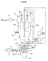
Specifically, as shown in Fig. 22, the raw material particles are
stored at the bottom of the granulating chamber 1. At this bottom, there is
mounted a rotor 42 rotatable about a vertical shaft 44. The rotor 42 defines
a number of vent holes, through which fluidizing air 6 is supplied from
under the rotor 42 to form an upwardly oriented air current inside the
granulating chamber 1, whereby the fluidizing layer R is formed
immediately above the rotor 42. To this fluidizing layer R, the liquid
material 3 is sprayed from spray nozzles 4 disposed upwardly and laterally
of the fluidizing layer R in directions opposed to and transverse the flow of
the fluidizing air 6, so as to grow the raw material particles to manufacture
the granules.
However, when this conventional manufacturing apparatus is
employed for manufacturing spherical and heavy granules with sharp size
distribution, the following problems exist.
Namely, with the conventional manufacturing apparatus, it is
necessary to prepare the raw material particles in advance inside the
granulating chamber. In order to charge them into the granulating
chamber to use them as raw material particles, certain conditions need to be
satisfied, such as the particles should not be coagulated easily and the size
distribution should be uniform. For this reason, the preparation of the raw
material would tend to be troublesome, imposing a certain limit in
improving the manufacturing efficiency of the granules.
Further, with the conventional manufacturing apparatus, the
spray nozzle 4 for downwardly spraying the liquid material 3 is disposed at
an upper position inside the granulating chamber 1. And, this spray nozzle
4 sprays the liquid material 3 in the direction opposing the air 6 blown
upward from the lower region of the granulating chamber 1. The liquid
material 3, which is formed into fine droplets (mist) as the result of spraying,
adheres to the raw material particles inside the fluidizing layer R to grow
these raw material particles. However, in order to ensure that the
downwardly sprayed liquid material 3 reaches the fluidizing layer R, it is
necessary to limit the momentum of the upwardly directed air 6 to a certain
extent. As a result, the space between the raw material particles inside the
fluidizing layer R becomes insufficient, thus tending to invite coagulation of
the raw material particles. For this reason, the granules obtained by using
the conventional manufacturing apparatus tend to have a wide size
distribution.
Moreover, the granules obtained by the above-described process
tend to have a structure with many voids. Hence, it was difficult to obtain
heavy granules.
Incidentally, another type of conventional apparatus includes a
mechanism for intermittently blowing high-pressure air against the
fluidizing layer R. For instance, the apparatus includes a plurality of jet
nozzles 46 mounted along the periphery of the apparatus body 2 for
discharging the air or gas against the fluidizing layer R. And, these
respective nozzles 46 are mounted so that the gas discharging directions
from all the nozzles will be focused at a single point within the fluidizing
layer R.
Then, the particles inside the fluidizing layer R will blown by the
high-pressure air currents toward the center of the granulating chamber 1
to collide against each other. This collision adds to the pulverizing effect of
the counter jet mill, so that the granules tending to coagulate will be
pulverized or cracked (hereinafter, "crushed"). Consequently, it becomes
possible to render the particle diameters of the resultant granules uniform.
However, with the conventional manufacturing apparatus, the
granules under granulation would coagulate easily. Hence, it was difficult
to allow the above-described crushing effect to manifest itself effectively.
The present invention is intended to solve the above-described
drawbacks of the conventional art and to provide a granule manufacturing
apparatus and method capable of manufacturing spherical and heavy
granules of a desired particle diameter in an efficient manner.
Disclosure of the Invention
The characterizing features of the granule manufacturing
apparatus and method relating to the present invention are as follows.
The granule manufacturing apparatus according to claim 1, as
shown in Fig. 1, is characterized in that the spray nozzle is designed to
spray the liquid material upwardly.
If the liquid material is sprayed upward as proposed by the above
construction, the spraying direction and the air supplying direction agree to
each other. So that the spraying of the liquid material will proceed
smoothly to ensure a sufficient floating period for the spray droplets of the
liquid material. Thus, these spray droplets will be solidified completely to
be formed into primary particles without coagulation with other primary
partides. The effect of prevention of coagulation can be provided also
during the subsequent process of the primary particles growing into the
granules.
If no coagulation of granules occurs during granulation as
described above, the granules will not combine each other to form granules
of an excessively large particle diameter. And, the growth of the granules
during granulation process will proceed in a continuos manner, so that
granules with reduced particle size difference may be obtained. For
instance, if granules having a narrower size distribution are obtained as
above, then, such additional device as a classifier, which is needed by the
standard manufacturing apparatus, would be omitted. Therefore, it
becomes possible also to form the manufacturing apparatus compact.
The granule manufacturing apparatus according to claim 2, as
shown in Fig. 1, is characterized in that the spray nozzle is disposed at a
lower center region of the granulating chamber.
With this construction, it is possible to ensure a large space along
the spraying direction of the liquid material. In addition, it is also possible
to minimize the possibility of adherence of the liquid material to the side
wall of the granulating chamber. Therefore, mutual coagulation of the
granules in the course of manufacture thereof may be restricted and the
floating and fluidized period of the spray droplets may be extended, whereby
the liquid material may be dried and solidified in a reliable manner.
The granule manufacturing apparatus according to claim 3, as
shown in Fig. 1, is characterized in that the granulating chamber includes a
generally conical wall portion having a progressively increasing width
upwardly.
Normally, the liquid material sprayed and fed into the granulating
chamber will be dispersed more as it floats and flows upwardly. Then, by
providing the generally conical wall portion as proposed by the above
construction, this serves to reduce the opportunity for the upwardly floating
granules to adhere to the wall portion. As a result, mutual coagulation of
granules may be further restricted and the floating period may be extended
also, whereby the drying and solidifying process of the granules may
proceed reliably.
The granule manufacturing apparatus according to claim 4, as
shown in Fig. 6, is characterized in that the apparatus further comprises
pressure applying means for momentarily increasing the pressure inside
the granulating chamber.
With this construction, it is possible to momentarily increase the
pressure inside the granulating chamber momentarily, thus applying
momentary external impact to the periphery of the granule in the course of
manufacture thereof. As a result, the granules will grow while being
compacted at the same time, whereby heavy granules having high strength
may be obtained.
The granule manufacturing apparatus according to claim 5, as
shown in Fig. 6, is characterized in that the apparatus further comprises a
filter capable of collecting the granules disposed between the spray nozzle
and the air exhaust port, and sweep-off means for sweeping off the granules
collected on the filter.
The spray droplets of the liquid material will float and flow inside
the granulating chamber while being dried and solidified. Since the air
inside the granulating chamber flows upward by the exhaustion through
the air blowoff portion, the granules of the liquid material too will be
gradually drawn to the upper region of the granulating chamber. Then;
with the above construction, the granules drawn upward will be collected by
the filter and these collected granules will be dried substantially completely
as they remain adhered to the filter. In these granules adhered to the filter,
any moisture present therein has evaporated, so that coagulation of the
granules due to the remaining moisture will hardly occur.
Then, the granules whose drying process has been completed on
the filter will be sweeped off by the sweep-off means provided to this filter.
The sweep-off mans may be various types, such as one for vibrating the
filter or applying back pressure to the filter.
The sweeped-off granules will again float and flow inside the
granulating chamber and the granules circulated to the vicinity of the spray
nozzle will be sprayed again with liquid material from the spray nozzle.
These granules coated with liquid material will be dried while floating and
flowing inside the granulating chamber and be adsorbed by the filter. With
repeated cycles of such growth process, granules having a desired particle
diameter may be formed.
By using the filter and the sweep-off means as proposed by the
above-described construction, granules having a predetermined particle
diameter may be manufactured within a limited space, so that the entire
manufacturing apparatus may be formed compact.
The granule manufacturing apparatus according to claim 6, as
shown in Fig. 6, is characterized in that the filter comprises a bag filter
having a backwashing unit. This bag filter provides the function of the
pressure applying means as well as the function of the sweep-off means.
The bag filter employed in the above construction will be disposed
at an upper region of the granulating chamber. This bag filter serves to
prevent the granules from being discharged to the outside of the apparatus
body when the air in the granulating chamber is exhausted and the filter
serves also as an area for allowing the granules to be dried. The granules
adhered to the bag filter may be sweeped off by the backwashing unit. The
backwashing unit serves to momentarily cause the air to flow reversely
through the filter inside the granulating chamber. Accordingly, when the
backwashing unit is in operation, the inside pressure of the granulating
chamber is increased.
As described above, through the effective utilization of the
backwashing unit both as the sweep-off means and as the pressure-applying
means, the construction of the manufacturing apparatus may be simplified.
And, in this case too, the resultant granules will be heavy, spherical and
have high strength.
The granule manufacturing apparatus according to claim 7, as
shown in Fig. 14, is characterized in that the granulating chamber includes
a jet nozzle for jetting high-pressure gas against the fluidizing layer.
With this construction, the granules which have become larger as a
result of coagulation in the granulation process may be crushed into a
suitable size by means of the high pressure air. Hence, granules having a
very narrow size distribution may be obtained. Moreover, by adjusting the
strength of the high pressure air, it becomes also possible to set the size of
the granules as desired.
The granule manufacturing apparatus according to claim 8, as
shown in Fig. 21, is characterized in that the apparatus further comprises a
downwardly directed spray nozzle disposed at an upper region inside the
granulating chamber for downwardly spraying the liquid material inside
the granulating chamber.
According to the manufacturing apparatus having the above
construction, the spraying operation of the liquid material inside the
granulating chamber is effected by means of the upwardly directed spray
nozzle disposed at a lower region of the granulating chamber as well as said
downwardly directed spray nozzle. With this construction, the liquid
material may be sprayed over a wider area of the granulating chamber.
Especially, in order to improve the granulating efficiency when a liquid
material having a high drying speed is employed, it is preferred that the
liquid material be sprayed by short time intervals. Then, according to this
construction, the liquid material is sprayed to nearly all positions inside the
granulating chamber. With this, additional liquid material may be caused
to adhere to the granulate present at nearly every position during the
manufacture process.
The granule manufacturing apparatus according to claim 9, as
shown in Fig. 21, is characterized in that the apparatus further comprises a
horizontally directed spray nozzle attached to the wall of the granulating
chamber for laterally spraying the liquid material relative to the fluidizing
air current inside the granulating chamber.
In this case too, by providing the horizontally oriented spray nozzle,
the liquid material may be sprayed over a wider area of the granulating
chamber. As a result, the amount of the liquid material adhered to each
granulate during the manufacture thereof may be rendered uniform, so that
the thickness of the liquid film formed on the surface of each granule may be
uniform as well. There will occur no sudden growth of granules, and the
adhesion and drying cycles of the liquid material may be repeated reliably.
Accordingly, no porous structure will be formed and uniform, dense and
heavy granules may be obtained.
The granule manufacturing apparatus according to claim 10, as
shown in Fig. 13, is characterized in that the bottom of the granulating
chamber is constructed of a rotor in the form of a generally circular disc.
By providing a rotor at the bottom of the granulating chamber as
proposed by the above construction, one can expect a compacting effect due
to the rolling in addition to the compacting effect from the pressure applying
means, whereby even heavier and stronger granules may be obtained.
Further, as the granules are caused to roll by the rotor, globurizing
of the granules may be further promoted.
Moreover, by providing the rotor, it is possible to manufacture
larger granules which can not be blown upward by the air from the air
blowoff portion. That is, such large granules will be accumulated on the
rotor. But, as this rotor is being rotated, the granules thereon too will roll
incessantly, so that the liquid material sprayed from the nozzle may be
caused to adhere to the surfaces of the granules uniformly.
The granule manufacturing apparatus according to claim 11, as
shown in Fig. 6 and Fig. 8, is characterized in that a jacket for circulating
fluid is provided over substantially entire outer periphery of the spray
nozzle for optimizing the temperature of the liquid material to be sprayed
and supplied.
If the jacket is provided over the substantially entire outer
periphery of the spray nozzle for optimizing the temperature of the liquid
material to be sprayed and supplied as proposed by the above-described
construction, it becomes possible to prevent solidification/deterioration of
the liquid material within the spray nozzle, so that continuous operation of
the manufacturing apparatus becomes readily possible.
Further, by Optimizing the temperature of the liquid material, the
viscosity of the liquid material may be made suitable for its spraying.
Accordingly, e.g. the particle diameter of the sprayed droplets may be
rendered uniform and the growth speed of the granules may be rendered
constant, whereby quality granules with uniform particle size may be
obtained.
The granule manufacturing apparatus according to claim 12, as
shown in Fig. 8, is characterized in that the spray nozzle includes a needle
at a spray opening thereof for spraying the liquid material, with the needle
being shiftable between an opening position for opening the spray opening
for the liquid material and a closing position for closing the spray opening
for the liquid material.
As proposed by the above construction, the needle capable of
opening/dosing the liquid material spraying opening ("liquid spray opening"
hereinafter) is used for closing the liquid material spraying opening when
the liquid material is not to be sprayed and for opening the liquid material
spraying opening when the liquid material is to be sprayed.
On the other hand, this liquid spray opening is exposed inside the
granulating chamber, thus exposed to the fluidizing air. Therefore, of the
liquid material present within the spray nozzle, especially a portion thereof
present adjacent the liquid spray opening tends to be dried and solidified
more easily. If it is solidified, this will lead to abnormality in the opening
area or shape of the liquid spray opening, thus resulting in change in the
spraying condition of the liquid material, consequently, non-uniformity in
the particle diameter of the sprayed droplets. As a result, it becomes
difficult to obtain granules of uniform particle size.
With the above-described construction including the needle
shiftable at the liquid material spraying opening, even if solidification of the
liquid material tends to occur at the liquid spray opening, the solidified
material may be eliminated by the needle. Accordingly, the liquid spray
opening may be maintained under a clean condition. As a result, the
manufacturing apparatus may be operated continuously for a longer period
of time, whereby the manufacturing efficiency of the granules may be
further improved.
The granule manufacturing apparatus according to claim 13, as
shown in Fig. 6, is characterized in that the spray nozzle is disposed at a
lower region inside the granulating chamber for upwardly spraying the
liquid material.
Especially, when the manufacture is to be started from a condition
where no raw material particles are charged at all in advance into the
granulating chamber, it is important to control the temperature, viscosity,
etc. of the liquid material. In particular, at the initial stage of the
granulation, the sprayed droplets of the liquid material are very small.
Therefore, it is important to control the spraying condition in order to e.g.
prevent mutual coagulation of the particles.
Then, if the spray nozzle having the jacket is directed upwards, it
becomes possible to optimize the spraying condition of the liquid material at
this initial stage of granulation, so that the liquid material may be dispersed
sufficiently inside the granulating chamber. Consequently, the
granulating efficiency may be improved significantly and granules having
narrow size distribution may be manufactured.
A method of manufacturing granules according to claim 14, as
shown in Fig. 1, is characterized by the steps of: discharging a
predetermined amount of air from an air blowoff portion without charging
any raw material particles into a granulating chamber; spraying/supplying
liquid material from a spray nozzle into the current of said air; causing
sprayed droplets of the liquid material to float and flow inside the
granulating chamber to form a group of particles; and spraying/supplying
additional liquid material from the spray nozzle to the group of floating and
flowing particles for growing the particles into granules.
As proposed by the above construction, if the liquid material is
sprayed and supplied to the current of air discharged upward, at the initial
stage of the granulation, the primary particles formed of the sprayed and
supplied liquid material may be caused to float and flow incessantly inside
the granulating chamber, thus allowing the primary particles to grow
without mutual coagulation thereof. Thus, a group of fine particles are
formed and consequently granules having a desired particle diameter and
also minimized particle diameter variation may be obtained.
Further, with this construction, there is no need for charging raw
material particles into the granulating chamber at the start of the
granulation. As the granules can be manufactured only by spraying the
liquid material, the manufacture efficiency of granules may be improved
significantly.
Brief Description of the Drawings
Fig. 1 is an explanatory figure schematically showing a granule
manufacturing apparatus relating to the present invention,
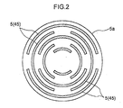
Fig. 2 is a plan view of an air blowoff member,
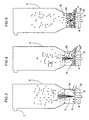
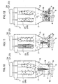
Figs. 3-5 are explanatory figures illustrating a manufacturing
process of granules,
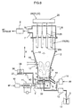
Fig. 6 is an explanatory figure schematically showing a granule
manufacturing apparatus relating to a second embodiment,
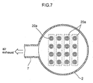
Fig. 7 is an explanatory figure showing an arrangement of a bag
filter relating to the second embodiment,
Fig. 8 is a vertical section of a nozzle of the manufacturing
apparatus relating to the second embodiment,
Fig. 9 is a plan view in section showing the nozzle of the
manufacturing apparatus relating to the second embodiment,
Figs. 10-12 are explanatory views illustrating a manufacturing
process of granules relating to the second embodiment,
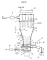
Fig. 13 is an explanatory view schematically showing a
manufacturing apparatus relating to a third embodiment,
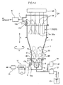
Fig. 14 is a vertical section showing a manufacturing apparatus
relating to a fourth embodiment,
Fig. 15 is a vertical section showing principal portions of the
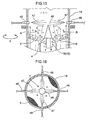
manufacturing apparatus relating to the fourth embodiment,
Fig. 16 is a plan view in section showing principal portions of the
manufacturing apparatus relating to the fourth embodiment,
Fig. 17 is a vertical section showing principal portions of a
manufacturing apparatus relating to a fifth embodiment,
Fig. 18 is an explanatory view showing an attachment condition of
a jet nozzle relating to a sixth embodiment,
Fig. 19 is an explanatory view showing an attachment condition of
a jet nozzle relating to a seventh embodiment,
Fig. 20 is a side view showing an attachment condition of a jet
nozzle relating to an eighth embodiment,
Fig. 21 is an explanatory view showing construction of a
manufacturing apparatus relating to a ninth embodiment, and
Fig. 22 is an explanatory view showing construction of a
conventional manufacturing apparatus.
Best Mode of Embodying the Invention
(first embodiment)
<general construction>
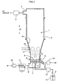
A granule manufacturing apparatus of the invention, as shown in
Fig. 1, includes, as major components thereof, an apparatus body 2 having a
granulating chamber 1, a spray nozzle 4 (simply "nozzle" hereinafter)
disposed at a lower region of the apparatus body 2 for spraying liquid
material 3 into the granulating chamber 1, and an air blowoff portion 5
disposed downwardly of the nozzle 4 for feeding fluidizing air 6 so as to form
a fluidizing layer R of granules inside the granulating chamber 1.
With the granule manufacturing apparatus of this invention, the
air 6 is blown or discharged from the air blowoff portion 5 upwardly into the
granulating chamber 1. The liquid material 3 is sprayed from the nozzle 4
also upwardly into the air 6. Sprayed droplets of the liquid material 3 will
float and flow inside the granulating chamber 1. Then, moisture contained
in the liquid material 3 will be evaporated, so that the droplets will be dried
and solidified to form fine primary particles. These primary particles will
be coated repeatedly and intermittently with additional liquid material 3
sprayed subsequently from the nozzle 4 to grow in their particle sizes,
whereby granules having a predetermined particle diameter are
manufactured.
Next, the individual components constituting the granule
manufacturing apparatus of the invention will be described
<apparatus body>
As shown in Fig. 1, the granule manufacturing apparatus of the
invention includes the generally cylindrical apparatus body 2. This
apparatus body 2 includes at substantially center thereof the granulating
chamber 1 for forming granules. This apparatus body 2 has a dividable
construction so that the body can be opened/closed at a predetermined
position along the vertical direction X, so as to e.g. facilitate maintenance
operation of the nozzle 4 or of the air blowoff portion 5.
In the instant embodiment, the granulating chamber 1 includes a
generally conical wall portion 15. In general, the liquid material 3 sprayed
and fed into the granulating chamber 1 tends to be dispersed more as it
flows and flows upward. Then, by providing the generally conical wall
portion 15 as in this construction, this arrangement serves to reduce
opportunity for the primary particles floating upward to adhere to the wall
portion 15. As a result, mutual coagulation of the primary particles or
sprayed droplets may be further restricted and their floating/flowing period
may be extended, so that the primary particles or the like may be dried and
solidified more reliably.
The slope angle of the wall portion 15 may be appropriately set,
depending on the spraying angle of the liquid material 3 from the nozzle 4.
For instance, assuming a conical plane including the wall portion 15, the
spray opening of the nozzle 4 may be located at the top of the cone. With
this construction, the spraying direction of the liquid material 3 from the
nozzle 4 agrees with the extending direction of the wall portion 15. Thus,
the possibility of adherence of the liquid material 3 to the wall portion 15
may be reduced.
Incidentally, the portion of the apparatus body 2 located on the side
of the nozzle 4 is formed cylindrical. allowing circulation of the fluidizing air
6. Accordingly, dispersion of the liquid material 3 sprayed from the nozzle
4 is restricted to some extent by the air 6. Considering this respect, the
slope of the conical face may be closer to vertical than the one described
above. For instance, assuming a conical plane including the wall portion
15, the slope may be set so that the spray opening of the nozzle 4 may be
located inwardly of the cone.
At the upper region of the apparatus body 2, there are provided an
air exhaust port 7 and an exhauster 8 for exhausting the air inside the
granulating chamber 1.
On the other hand, at the lower region of the apparatus body 2,
there are provided an air feed port 9 and a blower 10 for feeding air into the
granulating chamber 1 and an air heater 11.
<nozzle>
The nozzle 4 for spraying the liquid material 3 is disposed e.g. at a
lower region of the granulating chamber 1.
The liquid material 3 may be e.g. slurry of sodium nitrate, sodium
acetate, or titanium oxide, slurry of ceramic powder, slurry of medical
substance (ethenzamide probenecid, etc.), water solution for various food
products, such as water solution of cocoa, water of coffee, etc.
Incidentally, the liquid material 3 may be mixed with various
binders for promoting adhesion of respective granules.
The liquid material 3 is sprayed by the nozzle 4 toward the upper
region of the granulating chamber 1.
The liquid material 3 is drawn from a material vessel 13 by means
of a material feed pump 12 to be supplied to the nozzle 4. In the course of
this, the nozzle 4 is supplied with air for spraying from an air compressor 14.
Incidentally, the liquid material 3 and the air 4 are supplied via e.g. a
double pipe to the nozzle 4, which mixes them and sprays the liquid
material 3 mixed with the air. With this spraying, fine droplets of the
liquid material 3 will be effectively blown upward into the granulating
chamber 1 and the droplets float and flow inside the granulating chamber 1
to be dried and solidified.
<air blowoff portion>
The air blowoff portion 5 supplies upward the fluidizing air 6 which
has been adjusted to a predetermined temperature and moisture content.
These temperature and moisture content are determined mainly by using a
thermometer 16 and a hygrometer 17 attached to the wall portion 15 of the
granulating chamber 1. A plan view of the air blowoff portion 5 is shown in
Fig. 2. The air blowoff portion 5 is disposed at a lower region of the
granulating chamber 1. For instance, a disc-like air blowoff member 5a
thereof may be a punching plate or a stainless sintered plate. Also, the
portion may include a porous ceramic or filter material for providing a
number of apertures and may be disposed at the lower region of the
granulating chamber 1.
Incidentally, for forming the air blowoff portion 5, it is not
absolutely necessary to employ the air blowoff member 5a in the form of a
disc. For instance, the air blowoff portion 5 may be formed by using the
above-described stainless sintered plate. Specifically, it is possible to
employ a mesh-like member which is formed by intertwining fine stainless
wires and then sintering and molding them together. This material is
superior in heat resistance, corrosion resistance and strength. Hence, the
durability of the manufacturing apparatus may be improved, allowing wider
selection of its operation conditions to be set for granulation.
The pressure of the air should preferably be such that it may cause
the individual granules to float and flow inside the granulating chamber 1.
Especially, at the initial stage of the granulation process, in order to avoid
mutual coagulation of the primary particles, the discharge amount of the air
will be adjusted to ensure that the primary particles will float and flow
incessantly inside the apparatus body 2.
Further, the temperature and moisture content of the air should be
adjusted appropriately, depending on the degree of dryness of the primary
particles or sprayed droplets. This is because, for instance, if the drying of
the primary particles is slow, mutual coagulation of the primary particles
tends to occur, causing such inconvenience as widening of the size
distribution of the resultant granules.
The discharging of the air is effected generally upward. But, this
direction may be upward along the vertical direction X. Alternatively, it
may be discharged obliquely upward so as to form a swirling current of the
air inside the granulating chamber 1. When such swirling current is
formed, this will more positively lift up the granules in the course of their
manufacture, so that drying and solidification of the granules may be
further promoted.
<manufacturing process>
An example of the process of manufacturing granules having a
predetermined particle diameter using the manufacturing apparatus of the
invention is illustrated in Figs. 3-5. Fig. 3 illustrates an initial stage of
granulation for forming the primary particles as seeds. Fig. 4 illustrates
an intermediate stage of granulation in which additional liquid material 3 is
caused to adhere to the granules being manufactured. Fig. 5 illustrates a
final stage of granulation in which further additional liquid material 3 is
caused to adhere to the granules at the latter stage of manufacturing
process.
As illustrated in Fig. 3, first, a predetermined amount of fluidizing
air 6 is discharged in advance from the air blowoff portion 5, and into this
air flow, the liquid material 3 is sprayed from the nozzle 4. The air 6 has
been adjusted to a predetermined temperature by means of the air heater
11. Then, as described hereinbefore, at the initial stage of granulation, a
group of fine particles comprising the primary particles or granules are
produced.
Fig. 4 illustrates the intermediate stage of manufacturing process.
In this condition, those granules which have grown in particle diameters
with certain degree of progress of granulation are floating and moving at the
lower region of the granulating chamber 1. Whereas, the smaller granules
which have not grown to such degree are floating and moving at the upper
region of the granulating chamber 1. These small granules will adhere to
the surfaces of the grown granules present at the lower region of the
granulating chamber and will catch sprayed droplets of additional liquid
material 3 supplied subsequently. As a result, substantially all of the
granules will have a same particle diameter. By effecting this process in
repetition, granules having a predetermined particle diameter may be
obtained.
Fig. 5 illustrates the final stage of the manufacturing process. At
this stage, most of the granules have grown approximately to the target
particle diameter. Spraying of the liquid material 3 at this final stage is
effected for causing all of the sprayed material to adhere to the granules.
Since most of the granules are floating and moving at the lower region of the
granulating chamber 1, the sprayed liquid material 3 may be reliably
adhered to the granules moving in the vicinity of the nozzle 4.
Upon completion of the granulation, the granules may be taken out
appropriately from a product outlet 19 by operating an opening/closing lid
18.
As described above, according to the invention's granule
manufacturing apparatus for upwardly spraying the liquid material 3 and
causing the primary particles or the like to float and flow over a wide area,
granules are grown while restricting mutual coagulation of the granules.
Hence, it is possible to obtain granules having any desired particle diameter.
Moreover, the obtained granules have only very small particle size
variations.
Also, at the start of the granulation process, it is not necessary to
charge raw material particles as seeds into the granulating chamber 1.
The granules may be manufactured only by spraying of the liquid material 3.
Accordingly, the manufacturing efficiency of granules may be improved
significantly.
(second embodiment)
Fig. 6 schematically shows a manufacturing apparatus relating to
the second embodiment. This apparatus, relative to the apparatus shown
in Fig. 1, additionally includes a filter 20, a sweep-off means 21 for sweeping
off granules under granulation adhering to the filter 20 and a pressure
applying means 22 for momentarily increasing the pressure inside the
granulating chamber 1.
<filter>
The filter 20 is disposed at the upper region of the granulating
chamber 1 so as to prevent fine granules under granulation from being
exhausted when the air inside the granulating chamber 1 is exhausted.
Inside the granulating chamber 1, there is a constant upward flow
of the fluidizing air 6, so that the granules floating inside the granulating
chamber 1 tend to move toward the air exhaust port 7.
Then, by providing the filter 20 as proposed by this construction, it
is possible to prevent a portion of the floating granules from being
inadvertently discharged through the air exhaust port 7, so that the yield of
the liquid material 3 used in the granulation may be improved.
<sweep-off means>
The sweep-off means 21 is provided for sweeping off small granules
adhered to the filter 20 and dried thereon and then causing them to float
and move again inside the granulating chamber 1. With this sweep-off
means 21, it is possible to surely cause the granules under granulation to
float and move inside the granulating chamber 1, thus promoting growth of
the granules.
This sweep-off mans 21 may be various types, such as one for
vibrating the filter 20 or applying back pressure to the filter 20.
<pressure applying means>
The pressure applying means 22 is provided for increasing the
internal pressure of the granulating chamber 1 by predetermined intervals.
With this operation, it is possible to compact the granules under granulation
by the pressure applied thereto, so that especially heavy and dense granules
may be obtained.
<bag filter>
In this second embodiment, a bag filter 23 having a backwashing
unit 24 is employed for providing the functions of the filter 20, the sweep-off
means 21 and the pressure applying means 22. As shown in Fig. 6, the bag
filter 23 is disposed at the upper region of the granulating chamber 1.
This bag filter 23 includes a plurality of generally cylindrical filter
bodies 20a each having dimensions of 89 mm x 900 mm. Namely, the
filter bodies 20a prevent exhaust of fine granules and the granules under
granulation are dried.
The filter bodies 20a are arranged, for example, in a matrix of 4
columns x 4 rows as shown in Fig. 7. Fig. 7 is a view taken at a position
VII-VII in Fig. 6. This bag filter 23 is capable of collecting particles of
several µm. Therefore, even if the supply amount of air from the air
blowoff portion 5 becomes too large, the granules under granulation will not
be discharged inadvertently to the outside of the apparatus body 2.
With this provision of the bag filter 23, the granules under
granulation may be collected and dried in a reliable manner.
The backwashing unit 24 includes a pressure-air source 25
connected to a compressor (not shown) disposed outside the apparatus body
2 and a blow tube 26 attached to the vicinity of the respective filter bodies
20a. As this backwashing unit 24 applies momentary pressure to the filter
bodies 20a from the side of the air exhaust port 7 toward the granulating
chamber 1, granules adhering to the bag filter 23 are sweeped off. As
indicated by broken lines in Fig. 7, in this embodiment, of the total sixteen
filter bodies 20a, each four of them in a row are treated as a group, and
respective groups are backwashed one after another. By applying
momentarily high-pressure air in the reverse direction to each group by
predetermined time interval, fine granules adhered to and dried on the
filter bodies 20a are caused to again float and flow inside the granulating
chamber 1.
Though not shown, the pressure air source 25 includes e.g. a timer
for setting the time interval for application of the backwashing air pressure
or backwashing operation.
As described above, by providing the bag filter 23, it is possible to
prevent almost entirely inadvertent discharge of fine granules from the
granulating chamber 1. Further, since the discharge of fine granules is
prevented and the drying of these granules is effected reliably, it'is possible
to reduce the capacity of the granulating chamber 1. As a result, the
construction of the manufacturing apparatus may be very compact.
<nozzle>
Further, the manufacturing apparatus relating to this second
embodiment is constructed also that the nozzle can be temperature-adjustable
in order to optimize the spraying condition of the liquid material
3.
As shown in Fig. 8, this nozzle 4 has a triple construction. Namely,
the innermost space thereof is a liquid feed passage 27 for feeding the liquid
material 3. The next space outwardly of the innermost space is a pressure-air
feed passage 28 for feeding the compressed air for spraying. The
outermost space is a jacket 29 forming a temperature-adjusting passage 30
allowing passage of fluid therein for the temperature adjustment of the
nozzle 4. The liquid material 3 and the compressed air are merged
together at the leading end of the nozzle 4. Then, fine droplets of the liquid
material 3 will be positively sprayed upwards into the granulating chamber
1 and as they flow inside the granulating chamber 1, they are dried and
solidified.
Examples of the liquid material 3 sprayed by the nozzle 4 for which
the nozzle 4 needs to be maintained at an elevated temperature are
thermosoftening resin solution or sugar ester which are softened when
heated and detergent or flavor solution which lose viscosity when heated.
On the other hand, examples of the liquid material 3 which require
that the nozzle 4 be maintained at a low temperature are thermosetting
resin solution which is hardened when heated and coffee extract of juice
which loses its original flavor if heated. Further examples are slurry of
organic salts which deteriorate if heated or of ceramic powder which can be
easily evaporated and materials which make their supply difficult or
deteriorate in their quality if heated.
Incidentally, the liquid material 3 may be mixed in advance with
various binders in order to promote mutual adhesion of granules under
granulation.
These kinds of liquid material 3 are sprayed upwards by the nozzle
4 toward the upper region of the granulating chamber 1. As shown in Fig.
6, the liquid material 3 is drawn from the material vessel 13 by means of the
material feed pump 12 and fed to the nozzle 4. In the course of this, the
nozzle 4 is supplied also with the compressed air for spraying from the air
compressor 14.
As shown in Fig. 8, the liquid feed passage 27 incorporates therein
a bar-like needle 31. The leading end of this needle 31 can be freely
inserted into and retracted from a liquid-material spray opening 32. That
is, when the liquid material 3 is to be sprayed, the needle is retracted away
from the liquid-material spray opening to open up this spray opening.
When the liquid material 3 is not to be sprayed, the needle is inserted into
the liquid-material spray opening 32 to close this spray opening 32.
These operations are effected by supplying operating pressure air
to a needle air feed passage 33 provided beside the nozzle 4. Specifically,
by supplying the pressure air also to the needle air feed passage 33 in
association with the pressure air supplied to the pressure air feed passage
28, a pressure is applied to a flange portion 34 provided at the base end of
the needle 31. With this, the needle 31 is pushed down against an urging
force of a spring 35 provided on the back side of the flange portion 34. As a
result, the liquid material spray opening 32 is opened up to spray the liquid
material 3. When the supply of pressure air to the needle air feed passage
34 is stopped, the spring pushes back the needle 31 to close the liquid
material spray opening 32 again.
Incidentally, when the needle 31 closes the liquid material spray
opening 32, the leading end of the needle 31 projects from this liquid
material spray opening 32. That is to say, the liquid material spray
opening 32 is exposed inside the granulating chamber 1 to be exposed to the
fluidizing air 6. Therefore, of the liquid material 3 present inside the
nozzle 4, in particular, a portion of the material 3 located adjacent the liquid
spray opening 32 tends to be dried and solidified easily. If it is solidified,
this will lead to abnormality in the opening area or shape of the liquid spray
opening, thus resulting in change in the spraying condition of the liquid
material 3, consequently, non-uniformity in the particle diameter of the
sprayed droplets. As a result, it becomes difficult to obtain granules of
uniform particle size. Therefore, by providing the needle 31 movable into
and out of the liquid spray opening 32, even if the liquid material 3 begins to
solidify at the liquid spray opening 32, the solids if formed may be removed
always by the needle 31. So that, the liquid spray opening 32 may be
maintained under a clean condition, thus making it possible for the
manufacturing apparatus to be continuously operated for a long period of
time, thus further improving the manufacturing efficiency of the granules.
As shown in Fig. 8, with this granule manufacturing apparatus of
the invention, the nozzle 4 is provided with the jacket 29. This jacket 29
forms the temperature-adjusting passage 30 for adjusting the temperature
of the nozzle 4. By circulating fluid in this temperature-adjusting passage
30, the temperature of the jacket 29 is adjusted for optimizing the
temperature of the liquid material 3 to be sprayed and supplied. For this
reason, the jacket 29 is provided over substantially entire outer periphery of
the nozzle 4.
In this jacket 29, water as an example of the fluid is circulated.
This water is recycled back to the temperature-adjusting passage 30 by
using a circulation unit 36. Needless to say, other kinds of fluids than
water can be used if desired.
The circulation unit 36 includes a temperature adjusting
mechanism 37 having e.g. a temperature setting knob 38. By operating
this knob, the temperature of the water can be set to a predetermined value.
A circulation passage 39 for circulating water incorporates, at a certain
position thereof, a water temperature gauge 40 for detecting the water
temperature. Then, based on a detection value of this water temperature
gauge 40 and the set value on the temperature setting knob 38, the
temperature adjusting mechanism 37 is operated automatically.
Fig. 9 is a section taken long IX-IX in Fig. 8. As shown in Fig. 9,
the temperature adjusting passage 30 incorporates therein partitioning
elements 41 for causing water to flow in one direction relative to the inside
of the temperature adjusting passage 30. That is to say, by providing these
partitioning elements 41, it is possible to allow water inside the
temperature adjusting passage 30 to flow smoothly and uninterruptedly,
thus improving the heating/cooling efficiency of the nozzle 4.
As described above, by providing the jacket 29, it is possible to
optimize the temperature of the liquid material 3 to be sprayed and supplied.
Solidification or deterioration of the liquid material 3 within the nozzle 4
may be prevented and the continuous operation of the manufacturing
apparatus may be facilitated. Further, with optimization of the
temperature of the liquid material 3, the viscosity of the liquid material 3
may be made suitable for spraying. The particle diameter of the sprayed
droplets or the like may be made uniform and the growth rate of the
granules may be made uniform, so that quality granules having uniform
size distribution may be obtained.
<manufacturing process>
An example of the process of manufacturing granules having a
predetermined particle diameter using the manufacturing apparatus
relating to the second embodiment is illustrated in Figs. 10-12. Fig. 10
illustrates an initial stage of granulation for forming the primary particles
as seeds. Fig. 11 illustrates an intermediate stage of granulation in which
while the primary particles are being formed as seeds, additional liquid
material 3 is caused to adhere to the primary particles or the granules being
manufactured. Fig. 12 illustrates a final stage of granulation in which
further additional liquid material 3 is caused to adhere to the granules at
the latter stage of manufacturing process.
A predetermined amount of fluidizing air 6 is discharged in
advance from the air blowoff portion 5, and into this air flow, the liquid
material 3 is sprayed from the nozzle 4. The air 6 has been adjusted to a
predetermined temperature by means of the air heater 11.
In the course of the above, the strength of the air 6 supplied from
the air blowoff portion 5 is set such that as many as possible sprayed
droplets or primary particles may float and flow inside the granulating
chamber 1. In this case also, i.e. when the primary particles are caused to
float positively inside the granulating chamber 1, since the bag filter 23 is
provided at an upper region of the granulating chamber 1, the primary
particles or granules which have gained in particle diameters to some extent
will not be discharged inadvertently to the outside of the apparatus body 2.
Incidentally, when the bag filter 23 is sweeped off, the fine granules
will be dropped in a dispersed state. Hence, a large distance may be
obtained between the granules. Therefore, compared with a case in which
the liquid material 3 is sprayed downwards, it is possible to set the
concentration of the liquid material 3 high. This advantage of being able to
increase the concentration can be obtained not only at the initial stage of
granulation, but also at a subsequent sage when the growth of granules has
advanced to some extent. In particular, at such stage when the growth of
granules has advanced to some extent to form granules of larger diameters,
the concentration of the liquid material 3 may be further increased. This is
because the mass of the granules too increases, so that coagulation of
granules can be restricted even when a surface tension of the liquid or force
of inter-molecule attraction is applied thereto. As a result, a
correspondingly larger amount of liquid material 3 may be sprayed, so that
the growth of the granules can be positively accelerated.
The primary particles or granules collected by the bag filter 23 at
the initial stage of granulation substantially complete their drying on the
bag filter 23. And, as these granules adhering to the bag filter 23 have
become lighter since moisture or the like contained within the granules has
substantially evaporated. Thus, mutual coagulation among these
granules will hardly occur.
Fig. 11 illustrates the intermediate stage of manufacturing process.
The granules which have completed their drying on the bag filter 23 will be
sweeped off by the backwashing unit 24 provided to the bag filter 23 back
into the granulating chamber 1. And, these sweeped-off granules will
again float and flow inside the granulating chamber 1. And, when they
float and flow to the vicinity of the nozzle 4, the liquid material 3 is sprayed
again onto them from the nozzle 4. These granules coated with the liquid
material 3 will be dried while floating and flowing inside the granulating
chamber 1 and will be adsorbed to the bag filter 23. With repetition of
these stages; granules having a predetermined particle diameter will be
produced.
At this intermediate stage, those granules which have grown in
particle diameters with certain degree of progress of granulation are
floating and moving at the lower region of the granulating chamber 1.
Whereas, the smaller granules which have not grown to such degree are
floating and moving at the upper region of the granulating chamber 1.
These small granules will adhere to the surfaces of the grown granules
present or the small granules coagulate each other and grow. So that, with
lapse of time, substantially all of the granules will obtain a uniform particle
diameter.
With the granulating system relating to the second embodiment,
while the spraying of the liquid material 3 is carried out, the backwashing
unit 24 is operated to sweep off the granules adhered to the bag filter 23.
As this backwashing unit 24 has the function of the pressure applying
means 22, the internal pressure of the granulating chamber 1 is increased
periodically.
With such periodical increase of the pressure of the granulating
chamber 1, the fine particles adhered to the surfaces of the somewhat
grown granules may be compacted on these surfaces. If the pressure
applying means 22 is not operated, the liquid material 3 sprayed from the
nozzle 4 will only adhere to the peripheries of the granules by means of e.g.
the surface tension. And, when this adhered liquid material 3 is dried, the
individual portions of the material will be jointed only by means of the
adhesive force of binder or the like contained in the liquid material 3.
In contrast, when the backwashing unit 24 is operated to increase
intermittently the pressure around the granules, a fixed pressure will be
applied to each granule from all directions. Consequently, the respective
fine granules will be pressed against each other to be joined firmly, so that
heavy granules are formed. In this case, the density of the resultant
granules will show the largest value of granules formed by a manufacturing
apparatus of this type.
As described above, as granules having a high density are formed,
mutual coagulation among those granules having grown to some extent will
occur even less, s that granules having a uniform particle size may be
manufactured as a whole.
Further, during the manufacturing process, the individual
granules will collide frequently against the wall portion 15 of the
granulating chamber 1 and the air blowoff member 5a, etc. So that, the
shapes of the granules will be rendered uniform and substantially spherical
granules may be obtained.
In addition to the above, since the granules during manufacture
thereof grow while being compacted, the strength of the granule during the
manufacture is extremely high. Thus, it is possible to obtain hardly
breakable granules during the manufacture or when they are completed as
products.
Of the floating and flowing granules, those which have
substantially finished growing and gained in mass will float and flow at the
lower region of the granulating chamber 1. These granules having
substantially finished growing may be extracted from the product outlet 19
provided at a lower portion of the granulating chamber 1. This extracting
operation may be carried out in substantially same manner as that
described hereinbefore in the first embodiment.
Fig. 12 illustrates the final stage of the manufacturing process. At
this stage, most of the granules have grown approximately to the target
particle diameter. The flowing condition of the granules, the spraying
condition of the liquid material 3 , etc. at this stage are substantially same
as those of the first embodiment described hereinbefore.
As described above, according to the manufacturing apparatus of
the second embodiment, mutual coagulation among the primary particles or
the granules at the respective stage of the manufacturing process is
effectively restricted. Thus, granules having a desired particle diameter
may be obtained.
Further, with this manufacturing apparatus, as the granules are
grown with the operation of the pressure applying means 22, the granules
are particularly compacted during the manufacture, so that heavy, large
and strong granules having a high bulk density may be obtained.
Moreover, since such heavy granules are obtained, each of the
granules colliding against the wall portion 15 of the granulating chamber 1
during the manufacturing process will be subjected to the pressure evenly
from around. As a result, substantially spherical granules may be
obtained.
<example>
Next, there will be described an example in which granules of lactic
acid were manufactured by using the manufacturing apparatus according to
the second embodiment.
The granulating chamber 1 had a diameter of 350 mm and a floor
area of 0.096 m2. The liquid material 3 comprised 50% water solution of
lactic acid.
From the air blowoff portion 5, air of about 100°C was blown off at
the rate of 7.54Nm3/min. From the nozzle 4, the lactic acid solution was
sprayed with using air having a spraying air amount of 170 l/min and a
spraying air pressure of 5 kg/mc2.
The backwashing of the bag filter 23 was effected every 7 seconds
for each group consisting of 4 filter bodies one after another. The pressure
of this backwashing was 6 kgf/cm2.
The air exhaust condition from the air exhaust port 7 is determined
substantially by the spraying amount of the liquid from the nozzle 4. In
the case of this example, with the spraying under the above-described
conditions, the exhaust air temperature was 35°C and its relative humidity
was 60%.
By operating the manufacturing apparatus under the above-described
conditions for 200 minutes, a total amount of 31.5 kg of granules
was obtained.
The particle size distribution of the resultant granules was narrow,
compared with the particle size distribution of granules obtained by using
the conventional apparatus, i.e. the apparatus without the pressure
applying means 22 and operating with spraying the lactic acid solution
downwards.
Table 1 below show the bulk densities of the granules obtained by
the granule manufacturing apparatus of the invention.
| operating time (min) | 50 | 100 | 150 | 200 |
| bulk density (g/cc) | 0.68 | 0.71 | 0.73 | 0.77 |
| average particle diameter (µ/m) | 300 | 400 | 480 | 560 |
As apparent from Table 1, the longer the operating time, the higher
the bulk density of the resultant granules. That is to say, with this
manufacturing apparatus, there was achieved the effect of compacting the
granules during the manufacture process, so that heavy granules were
formed.
On the other hand, Table 2 below shows the influence of the
backwashing operation on the bulk density of the granules. The bulk
density values were those obtained after the manufacturing apparatus was
operated for 200 minutes.
| backwashing interval (sec) | 7 | 14 | 20 |
| bulk density (g/cc) | 0.82 | 0.79 | 0.76 |
As may be apparent from the above results, the shorter the interval
of backwashing operation, the higher the bulk density of the granules.
Hence, it may be understood that the pressure applying means provides the
compacting effect on the granules.
Incidentally, the nozzle 4 disclosed in this second embodiment can
be employed not only in the manufacturing apparatus of this embodiment,
but may be employed in the manufacturing apparatuses of all of the
embodiments of the invention disclosed herein.
[third embodiment]
The granule manufacturing apparatus of the invention, as shown
in Fig. 13, may include a rotor 42 disposed at the bottom of the granulating
chamber 1. This rotor 42 provides the function of blowing off air 6 into the
granulating chamber 1. Also, this rotor 42 provides another function of
causing accumulated granules under manufacture to roll and applying an
external force to the granules for compacting them to finish them into
spherical shape.
This rotor 42 can be formed of e.g. a plate-like member having a
plan shape as shown in Fig. 2 for example. And, this rotor is rotatably
driven by means of a motor 43 disposed below about a shaft 44 along the
vertical direction X. The rotational speed of the rotor 42 can be varied
appropriately by controlling the motor 43.
The rotor 42 defines a plurality of arcuate slits 45 like those shown
in Fig. 2 described hereinbefore. In these slots 45, those located dose to the
outer periphery have longer total lengths, whereby the air supply amount
may increase on the outer side of the rotor 42. This is because, especially
when the rotor 42 is rotated, the granules are scattered to the outer side of
the rotor 42 thereby to increase of the amount of the granules accumulated
on the outer periphery of the rotor 42, so that a greater amount of air 6
needs to be blown off at this portion.
Incidentally, in addition to the conventional porous plate such as a
punching plate, the rotor 42 may employ also a conventional porous
material. Further, if needed, a stirrer such as a stirrer blade may be
additionally provided.
Hence, with the provision of the rotor 42, in addition to the
compacting effect provided by the pressure applying means 22, a further
compacting effect due to the rolling movement can also be expected,
whereby heavier and firmer granules may be obtained.
Moreover, by rolling the granules by the rotor 42, globurizing of the
granules may be further promoted.
In addition, by providing the rotor 42, it becomes possible to
manufacture larger granules which could not be blown up by the air 6 from
the air blowoff portion 5. Such large granules will be accumulated on the
rotor 42. However, as the rotor 42 is being rotated, this will constantly roll
the granules, so that the liquid material 3 sprayed from the nozzle 4 may be
applied to the surfaces of the granules in an uniform manner.
[fourth embodiment]
A further embodiment of a manufacturing apparatus relating to
the present invention is illustrated in Fig. 14.
This manufacturing apparatus is characterized in that the
apparatus includes jet nozzles 46 for jetting high-pressure air to a lower
region of the granulating chamber 1. The remaining basic construction of
the apparatus is same as that of the manufacturing apparatuses of the
above-described respective embodiments. By using this manufacturing
apparatus, it is possible to obtain granules of particularly high quality.
The resultant granules are often employed as a pharmaceutical product.
The tablets formed by compressing the granules can be dissolved speedily
after administration thereof. Hence, these are particularly suitable as a
pharmaceutical product to be aspirated from the nasal cavity, for instance.
The jet nozzle 46 is provided to the wall portion 15 of the apparatus
body 2. In the case of this embodiment, the pulse jet 47 is jetted from the
respective jet nozzle 46. This pulse jet 47 comprises intermittent jetting of
dry compression air.
Figs. 15 and 16 illustrate an example in which four jet nozzles 46
are distributed along the peripheral direction of the wall portion 15. All of
these four jet nozzles 46 are disposed with a horizontal inward orientation
when the apparatus body 2 is seen in a side view. They are also disposed in
such a manner that the pulse jets 47 thereof will intersect each other at the
center of the apparatus body 2 when the apparatus body 2 is seen in a plan
view. With this construction, the granules which have grown too large as a
result of coagulation thereof will be crushed instantaneously as being
directly impinged on by the pulse jets 47.
Further, the granules or the like which were not crushed directly
will also be moved inwardly in the apparatus body 2 by the pulse jets 37
ejected from the four positions, so that these granules will be caused to
strongly collide against each other in the vicinity of the center portion to be
crushed thereby. Accordingly, it is possible to restrict the growth of
granules to a predetermined range, whereby granules having a desired
granule diameter can be obtained.
Incidentally, in order to obtain such granules having a desired
granule diameter, it is necessary to maintain the temperature/humidity
inside the granulating chamber appropriately. For instance, if the liquid
material 3 dries too slowly, the coagulation among the granules tends to
occur, leading to a wide size distribution of the resultant granules. For this
reason, the temperature/humidity of the fluidizing air 6 will be
appropriately adjusted, depending on the drying degree of the sprayed
droplets, etc. These temperature and humidity are measured by an
entrance thermometer 16 and an entrance hygrometer 17 provided to the
air feed port 9. The fluidizing air 6 past the granulating chamber 6 will be
discharged from the air exhaust port 7 by using the exhauster 8. In doing
this, the temperature and humidity of the exhausted fluidizing air 6 will be
measured by an exit thermometer 16b and an exit hygrometer 17b provided
to the air exhaust port 7.
The results of measurement of the temperature and humidity at
the air exhaust port 7 together with the results of measurement of the
temperature and humidity at the air feed port 9 are useful for grasping and
adjusting the temperature and humidity conditions inside the granulating
chamber 1. That is, by appropriately adjusting the air supply amount or
humidity of the fluidizing air 6 based on the measurement results, it is
possible to optimize the temperature/humidity inside the granulating
chamber 1.
In this embodiment, a plurality of nozzles 4 for jetting the liquid
material 3 upwardly are disposed at positions offset from the center of the
bottom of the granulating chamber 1. By providing a plurality of nozzles in
this manner, it is possible to spray the liquid material 3 to the entire inside
of the granulating chamber 1. Accordingly, it is possible to minimize the
mutual coagulation of the granules in the course of manufacture thereof
Also, by providing a plurality of nozzles, it is possible to enlarge the
granulating chamber 1 correspondingly.
According to this embodiment, as shown in Figs. 15 and 16, the air
blowoff portion 5 is disposed around a cone member 48 having a conical face
and can be moved downwardly relative to this cone member 48. With this
downward movement, there is formed a gap 49 between the cone member
48 and the air blowoff portion 5. This gap 49 is utilized as a product outlet
19 for taking out the granules whose granulation has been completed.
With this construction, it is possible to manufacture granules in a
continuous manner.
As described above, the sprayed liquid material 3 will float and flow
inside the granulating chamber 1 to be formed into fine primary particles.
And, as additional liquid material 3 is sprayed onto these fine primary
particles 1, there are formed granules having dense structure; and those
granules which have grown to a certain extent will collide against each
other to be coagulated, whereby large granules will be formed.
The granules which have coagulated and increased in weight will
form a fluidizing layer R at the lower region of the granulating chamber 1.
However, as these coagulated granules are subjected to the pulse jets 47 as
described above, the granules will be crushed, thus inhibiting growth
thereof beyond a predetermined size. That is, with the apparatus of the
present invention, there may be formed granules each formed by
coagulation of particles of a predetermined size.
The granules obtained by the granulation using the pulse jets 47
described above exhibited a cross section condition having more voids than
those obtained without using such pulse jets 47.
The bulk density of the granules showed a smaller value when the
pulse jets 47 were employed. Further, this bulk density decreased as the
pressure of the pulse jet 47 increased. This is believed to be attributable to
the fact that higher pressure of the pulse jet 47 restricts the grown of
individual granule forming the granule so as to form granules with
increased voids therein.
The size of the resultant granules can be adjusted by adjusting the
pulse interval when the pulse jets 47 are jetted or the jetting pressure of the
pulse jets 47. For instance, the shorter the jetting interval of the pulse jet
47 and the higher the jetting pressure of the pulse jet 47, the smaller the
size of the resultant granule. This is because the pulse jet 47 having a
higher pressure can apply a higher impact to the granule under
manufacture. Moreover, the higher the pressure, the larger the area the
pulse jet 47 can exerts its effect inside the granulating chamber 1, thereby
increasing the opportunity for a particular granule to be subjected to the
impact from the pulse jet 47, thus restricting excessive growth of the
granule.
The granules obtained by this manufacturing apparatus provide
superior fluidity when charged into a mold and provide also a shorter period
until the granules are crushed when subjected to an external force.
Accordingly, the granules having such properties can be readily charged
into a mold and can be formed into tablets easily.
The hardness of the tables formed by compression of these granules
tends to be higher as the pressure of the pulse jets 47 is increased. And,
with higher pressure of the pulse jets 47, the resultant granules have more
voids therein. However, such granules can be broken more easily than
dense granules. Then, the granules will be crushed speedily inside the
mold during the tablet forming process, thus providing increased compacted
strength, thus increased hardness.
(fifth embodiment)
The type of the jet nozzle 47 is not limited to the foregoing
embodiments, but may have an alternative construction shown in Fig. 17.
That is, the spraying direction of the pulse jet 47 may be oriented to the
center of the granulating chamber 1 and with slight lower inclination as
well.
With this construction, the pulse jet 47 will be jetted in the
direction opposing the granules applied with the upward velocity by the
fluidizing air 6, so that an even stronger impact may be applied to these
granules. As a result, even such granules having a stronger mutual
coagulating force can be manufactured with effectively restricting
coagulation thereof.
In this embodiment, for taking out the granules, the cone member
48 is adapted to be moved upward. This vertical movement of the cone
member 48 is provided by e.g. an operation of a lever member attached to
the support shaft of the cone member 48. This operation can be manual or
automatic. In the case of automatic operation, this may be done by
operating the lever member by predetermined intervals or by operating the
same based on detection of e.g. the weight of the formed granules. Any
other construction can also be employed as desired.
(sixth embodiment)
The jet nozzles 46 employed in the fifth embodiment above are
provided at four positions along the periphery of the granulating chamber 1
as shown in Fig. 18. Adjacent two jet nozzles 46 form a pair and jets of this
pair of jet nozzles 46 will intersect each other inside the fluidizing layer R.
And, a further arrangement is made such that the intersection point of one
pair of pulse jets 47 is different from the intersection point of the other pair
of pulse jets 47.
With this construction, the crushing of the granules inside the
fluidizing layer R takes place at a plurality of locations, so that the effective
area of the crushing force of the pulse jets 47 can be extended It should be
noted, however, that in this case, the impact force to the granules will be
smaller than the construction of Fig. 17. However, when granules having
not so strong coagulating force are to be manufactured, it can be more
effective to extend the effective area of the impact force than to increase the
impact force. With the manufacturing apparatus of this construction, it is
possible to efficiently manufacture granules having not so strong
coagulating force during the manufacture thereof
Moreover, by appropriately selecting the total number of the jet
nozzles 46 employed, the number of the positions where the pulse jets 47
intersect each other, or the number of the jet nozzles 46 employed for
causing the pulse jets 47 to intersect at a single point, it becomes readily
possible to enlarge the apparatus.
(seventh embodiment)
The jet nozzles 46 may further alternatively constructed as shown
in Fig. 19. Namely, a plurality of jet nozzles 46 are provided along the
periphery of the granulating chamber 1 and the orientation of each jet
nozzle 46 is offset by a predetermined angle from the center of the
granulating chamber 1, thereby forming a swirling type fluidizing layer R.
With this construction, in comparison with the case shown in
Figs.17 and 18, it is possible to further reduce the impact forces of the pulse
jets 47. Moreover, as these impact forces can be distributed uniformly over
the entire fluidizing layer R, the construction will be useful for e.g. allowing
very fragile granules grow to a predetermined size.
(eighth embodiment)
The manufacturing apparatus relating to the present invention
may be alternatively constructed such that a plurality of jet nozzles 46 are
distributed along the vertical direction X as shown in Fig. 20.
Of these, those jet nozzles 46 disposed at lower positions are
mounted with a slight upward orientation, whereas the other jet nozzles 46
disposed at upper positions are mounted with a slight downward orientation.
The construction for causing the high-pressure airs from these two jet
nozzles 46 to intersect each other is same as those employed in the foregoing
embodiments.
With this construction too, like the sixth embodiment described
above, it is readily possible to enlarge the manufacturing apparatus.
Incidentally, the jet nozzles 46 disclosed in the above-described
fourth through eighth embodiments can be used not only for the
manufacturing apparatuses of the respective embodiments corresponding
thereto, but can be used for the manufacturing apparatuses of all
embodiments disclosed herein.
(ninth embodiment)
As shown in Fig. 21, the granule manufacturing apparatus of the
present invention may include further nozzles 4 for spraying the liquid
material downwardly and laterally, in addition to the upwardly oriented
nozzles 4. In this discussion, the upwardly oriented nozzle will be referred
to as a first nozzle 4a, the downwardly oriented nozzle will be referred to as
a second nozzle 4b and the laterally or horizontally oriented nozzle will be
referred to as a third nozzle 4c, respectively.
As shown in Fig. 21, the second nozzle 4b extends from the wall
portion 15 of the apparatus body 2. to the center of the apparatus body 2 so
as to spray the liquid material 3 downwardly at the center of the apparatus
body 2. The third nozzle 4c may be attached to the wall portion 15 of the
apparatus body 2, for instance.
The supply amount ratio of the liquid material 3 to each of the
above-described nozzles 4a, 4b, 4c can be varied as desired by means of
valves 53 provided downstream of the material feed pump 12.
The spraying operations of the liquid material 3 from these nozzles
4a, 4b, 4c can be effected continuously or intermittently. Further, it is
possible to arrange so that the respective nozzles 4a, 4b, 4c effect the
spraying operations thereof alternatively to each other. In short, it is
necessary to appropriately vary the spraying condition so as to allow the
liquid material 3 to be applied to the surface of each granule under
manufacture uniformly.
Further, although Fig. 21 shows an example using the three kinds
of nozzles 4a, 4b, 4c, it is also possible to employ only the first nozzle 4a and
the second nozzle 4b, without using the third nozzle 4c.
The construction of this embodiment in which the liquid material 3
is sprayed from the plurality of nozzles 4a, 4b, 4c provides the following
advantages.
For instance, when the manufacturing operation is effected by
spraying the liquid material 3 without charging raw material particles into
the granulating chamber 1, during the initial stage of the granulation, it is
possible to reserve a greater inter-distance between the primary particles
formed by drying and solidification of the sprayed droplets of the liquid
material 3. Hence, it is possible to restrict mutual coagulation of the
primary particles, so that very small granules can be manufactured.
Also, at the subsequent stage when the primary particles have
grown to a certain extent to form granules, it is possible to allow the
additional liquid material 3 to be applied uniformly to the individual
particles. Hence, it is possible to render the growth degree of the
individual particles uniform as well.
If the spraying operation is effected by distributing the liquid
material 3 by using the second nozzle 4b and the third nozzle 4c, the amount
of the liquid material 3 to be applied to each granule will be rendered
uniform, so that a thinner liquid layer may be formed on the surface of the
granule. Thus, the drying of the liquid film will take place reliably, thus
reducing the possibility that the vicinity of the granule surface remains undried
and undesired additional liquid film is applied thereto. As a result, a
porous structure will hardly be formed. Moreover, since the granules are
constantly compacted by means of the pressure applying means 22, heavier
granules may be obtained.
Incidentally, in the case of using the apparatus of Fig. 21 too, it is
possible to charge raw material particles for use in the manufacture of
granules into the apparatus body 2 prior to the granulation, so that the
particles are subsequently subjected to e.g. a coating process using the three
nozzles 4a, 4b, 4c. In this case, for instance, the raw material particles may
be charged from a particle supply inlet 52 formed in the wall portion 15 of
the apparatus body 2. By using this particle supply inlet 52 and the
product outlet 19, a continuous granulation operation is made possible.
(air ionizing means)
The manufacturing apparatus shown in Fig. 21 includes the jet
nozzles 46. From these jet nozzles 46, high-pressure air ionized by air
ionizing means 54 is blown out. Namely, by ionizing the high pressure air,
static electricity generated in association with the granulation process is
neutralized, thus preventing mutual coagulation of the granules or
generation of a spark.
The air ionizing means 54 may comprise electrodes attached to the
leading end of the respective jet nozzle 46. Then, as a high voltage is being
generated between the electrodes, the high pressure air is sprayed to flow
adjacent the electrodes, so that the molecules of the high pressure air are
broken down to generate ions of positive polarity and ions of negative
polarity, thus producing the ionized air.
With the provision of this means, it is possible to neutralize
charging of the granules which would occur otherwise with progress of
drying of the granules. As a result, mutual coagulation of the granules
may be restricted and the crushing of the granules may take place in an
efficient manner.
Further, with neutralization of charging effect, it is possible to
manufacture such highly ignitable granules in a safe manner.
(vapor feeding means)
The granule manufacturing apparatus of this embodiment includes
a vapor feeding means 55 disposed downwardly of the air blowoff portion 5.
This vapor feeding means 55 is employed for e.g. sterilizing the granules to
be manufactured.
This vapor feeding means 55 comprises e.g. an annular circular
vapor spraying pipe 56. Into this vapor spraying pipe 56, steam is supplied
from the outside of the apparatus body 2. And, the steam is sprayed
upwardly from nozzle holes formed in the upper face of the vapor spraying
pipe 56. The spraying of vapor may be carried out in a desired manner.
For instance, a plurality of spraying operations may be effected at the final
stage after completion of the granulation process of the granules.
The vapor feeding means 55 may be used also for other purposes
than sterilization of the granules, including removal of clogging of the air
blowoff portion 5 or the slits 45 and cleaning of the inside of the apparatus
body 2. Such cleaning operations will be effected after the granules are
discharged upon completion of the intended granulation process.
(tenth embodiment)
In the foregoing embodiments, ordinary air is employed as the
fluidizing air 6 and/or the high-pressure air. Instead, e.g. ozone gas may be
employed. When ozone gas is employed, it is possible to achieve the
sterilizing effect on the granules.
Further, it is not necessary to supply ozone gas at all of the
granulating stages. It may be supplied only at certain steps by an amount
required for sterilization of granules.
The ozone gas may be supplied from either one or both of the air
blowoff portion 5 and the jet nozzles 46.
Industrial Applicability
By using the granule manufacturing apparatus and method of the
present invention, it is possible to manufacture e.g. granules of sodium
nitrate, sodium acetate, titanium oxide, ceramic powder, medical product
(ethenzamide probenecid, etc.), or granules for use in a variety of food
products such as cocoa, coffee, etc.
Further, it is also possible to effect granulation of such materials as
thermosetting resin solution which is hardened when heated, or coffee
extract liquid, juice liquid etc. which loses its flavor if heated, or other
materials which become difficult to be supplied or deteriorate in quality
when heated, such as organic salts which deteriorate when heated or a
slurry of highly volatile ceramic powder. etc.