EP1195188A1 - Chemical filter - Google Patents
Chemical filter Download PDFInfo
- Publication number
- EP1195188A1 EP1195188A1 EP01308415A EP01308415A EP1195188A1 EP 1195188 A1 EP1195188 A1 EP 1195188A1 EP 01308415 A EP01308415 A EP 01308415A EP 01308415 A EP01308415 A EP 01308415A EP 1195188 A1 EP1195188 A1 EP 1195188A1
- Authority
- EP
- European Patent Office
- Prior art keywords
- chemical filter
- gas
- unit body
- adsorbent
- concentration
- Prior art date
- Legal status (The legal status is an assumption and is not a legal conclusion. Google has not performed a legal analysis and makes no representation as to the accuracy of the status listed.)
- Withdrawn
Links
- 239000000126 substance Substances 0.000 title claims abstract description 52
- 239000003463 adsorbent Substances 0.000 claims abstract description 32
- QGZKDVFQNNGYKY-UHFFFAOYSA-N Ammonia Chemical compound N QGZKDVFQNNGYKY-UHFFFAOYSA-N 0.000 claims abstract description 20
- 229910021529 ammonia Inorganic materials 0.000 claims abstract description 10
- 238000009835 boiling Methods 0.000 claims abstract description 6
- 238000011144 upstream manufacturing Methods 0.000 claims description 11
- 229920001971 elastomer Polymers 0.000 claims description 8
- NBVXSUQYWXRMNV-UHFFFAOYSA-N fluoromethane Chemical compound FC NBVXSUQYWXRMNV-UHFFFAOYSA-N 0.000 claims description 8
- XLYOFNOQVPJJNP-UHFFFAOYSA-N water Substances O XLYOFNOQVPJJNP-UHFFFAOYSA-N 0.000 claims description 8
- 125000006850 spacer group Chemical group 0.000 claims description 7
- 239000003960 organic solvent Substances 0.000 claims description 3
- 229910052782 aluminium Inorganic materials 0.000 claims description 2
- XAGFODPZIPBFFR-UHFFFAOYSA-N aluminium Chemical compound [Al] XAGFODPZIPBFFR-UHFFFAOYSA-N 0.000 claims description 2
- 239000007789 gas Substances 0.000 abstract description 63
- 238000004519 manufacturing process Methods 0.000 abstract description 10
- 239000004065 semiconductor Substances 0.000 abstract description 9
- KFZMGEQAYNKOFK-UHFFFAOYSA-N Isopropanol Chemical compound CC(C)O KFZMGEQAYNKOFK-UHFFFAOYSA-N 0.000 description 27
- 230000000052 comparative effect Effects 0.000 description 9
- 238000000034 method Methods 0.000 description 7
- HEMHJVSKTPXQMS-UHFFFAOYSA-M Sodium hydroxide Chemical compound [OH-].[Na+] HEMHJVSKTPXQMS-UHFFFAOYSA-M 0.000 description 6
- YXFVVABEGXRONW-UHFFFAOYSA-N Toluene Chemical compound CC1=CC=CC=C1 YXFVVABEGXRONW-UHFFFAOYSA-N 0.000 description 6
- 238000004140 cleaning Methods 0.000 description 6
- IJGRMHOSHXDMSA-UHFFFAOYSA-N Atomic nitrogen Chemical compound N#N IJGRMHOSHXDMSA-UHFFFAOYSA-N 0.000 description 5
- 229920002449 FKM Polymers 0.000 description 5
- 230000003247 decreasing effect Effects 0.000 description 5
- 229910001873 dinitrogen Inorganic materials 0.000 description 5
- 239000005416 organic matter Substances 0.000 description 5
- QTBSBXVTEAMEQO-UHFFFAOYSA-N Acetic acid Chemical compound CC(O)=O QTBSBXVTEAMEQO-UHFFFAOYSA-N 0.000 description 3
- 238000001816 cooling Methods 0.000 description 3
- 238000010586 diagram Methods 0.000 description 3
- MTHSVFCYNBDYFN-UHFFFAOYSA-N diethylene glycol Chemical compound OCCOCCO MTHSVFCYNBDYFN-UHFFFAOYSA-N 0.000 description 3
- 238000010438 heat treatment Methods 0.000 description 3
- 239000011261 inert gas Substances 0.000 description 3
- KRHYYFGTRYWZRS-UHFFFAOYSA-N Fluorane Chemical compound F KRHYYFGTRYWZRS-UHFFFAOYSA-N 0.000 description 2
- 239000000356 contaminant Substances 0.000 description 2
- 238000011109 contamination Methods 0.000 description 2
- KSMVZQYAVGTKIV-UHFFFAOYSA-N decanal Chemical compound CCCCCCCCCC=O KSMVZQYAVGTKIV-UHFFFAOYSA-N 0.000 description 2
- 238000002290 gas chromatography-mass spectrometry Methods 0.000 description 2
- 238000007789 sealing Methods 0.000 description 2
- 239000002356 single layer Substances 0.000 description 2
- 235000011121 sodium hydroxide Nutrition 0.000 description 2
- 238000004506 ultrasonic cleaning Methods 0.000 description 2
- 229910002651 NO3 Inorganic materials 0.000 description 1
- NHNBFGGVMKEFGY-UHFFFAOYSA-N Nitrate Chemical compound [O-][N+]([O-])=O NHNBFGGVMKEFGY-UHFFFAOYSA-N 0.000 description 1
- CTQNGGLPUBDAKN-UHFFFAOYSA-N O-Xylene Chemical compound CC1=CC=CC=C1C CTQNGGLPUBDAKN-UHFFFAOYSA-N 0.000 description 1
- VYPSYNLAJGMNEJ-UHFFFAOYSA-N Silicium dioxide Chemical compound O=[Si]=O VYPSYNLAJGMNEJ-UHFFFAOYSA-N 0.000 description 1
- XUIMIQQOPSSXEZ-UHFFFAOYSA-N Silicon Chemical compound [Si] XUIMIQQOPSSXEZ-UHFFFAOYSA-N 0.000 description 1
- XSTXAVWGXDQKEL-UHFFFAOYSA-N Trichloroethylene Chemical group ClC=C(Cl)Cl XSTXAVWGXDQKEL-UHFFFAOYSA-N 0.000 description 1
- 230000002378 acidificating effect Effects 0.000 description 1
- 239000003513 alkali Substances 0.000 description 1
- 230000005587 bubbling Effects 0.000 description 1
- 239000010730 cutting oil Substances 0.000 description 1
- 238000003795 desorption Methods 0.000 description 1
- 230000006866 deterioration Effects 0.000 description 1
- 230000000694 effects Effects 0.000 description 1
- 238000011156 evaluation Methods 0.000 description 1
- 239000000945 filler Substances 0.000 description 1
- 239000001307 helium Substances 0.000 description 1
- 229910052734 helium Inorganic materials 0.000 description 1
- SWQJXJOGLNCZEY-UHFFFAOYSA-N helium atom Chemical compound [He] SWQJXJOGLNCZEY-UHFFFAOYSA-N 0.000 description 1
- 229960002050 hydrofluoric acid Drugs 0.000 description 1
- 238000004255 ion exchange chromatography Methods 0.000 description 1
- 150000002500 ions Chemical class 0.000 description 1
- 239000010410 layer Substances 0.000 description 1
- 238000003754 machining Methods 0.000 description 1
- 239000000463 material Substances 0.000 description 1
- 238000005259 measurement Methods 0.000 description 1
- 229910052751 metal Inorganic materials 0.000 description 1
- 239000002184 metal Substances 0.000 description 1
- 239000004745 nonwoven fabric Substances 0.000 description 1
- 239000003921 oil Substances 0.000 description 1
- 230000003287 optical effect Effects 0.000 description 1
- 238000005457 optimization Methods 0.000 description 1
- 238000004806 packaging method and process Methods 0.000 description 1
- 229920001084 poly(chloroprene) Polymers 0.000 description 1
- 230000002035 prolonged effect Effects 0.000 description 1
- 230000000979 retarding effect Effects 0.000 description 1
- 238000005070 sampling Methods 0.000 description 1
- 239000000741 silica gel Substances 0.000 description 1
- 229910002027 silica gel Inorganic materials 0.000 description 1
- 229910052710 silicon Inorganic materials 0.000 description 1
- 239000010703 silicon Substances 0.000 description 1
- 229940083608 sodium hydroxide Drugs 0.000 description 1
- 239000002904 solvent Substances 0.000 description 1
- 239000000758 substrate Substances 0.000 description 1
- UBOXGVDOUJQMTN-UHFFFAOYSA-N trichloroethylene Natural products ClCC(Cl)Cl UBOXGVDOUJQMTN-UHFFFAOYSA-N 0.000 description 1
- 238000004073 vulcanization Methods 0.000 description 1
- 238000005406 washing Methods 0.000 description 1
- 239000008096 xylene Substances 0.000 description 1
Images




Classifications
-
- B—PERFORMING OPERATIONS; TRANSPORTING
- B01—PHYSICAL OR CHEMICAL PROCESSES OR APPARATUS IN GENERAL
- B01D—SEPARATION
- B01D53/00—Separation of gases or vapours; Recovering vapours of volatile solvents from gases; Chemical or biological purification of waste gases, e.g. engine exhaust gases, smoke, fumes, flue gases, aerosols
- B01D53/02—Separation of gases or vapours; Recovering vapours of volatile solvents from gases; Chemical or biological purification of waste gases, e.g. engine exhaust gases, smoke, fumes, flue gases, aerosols by adsorption, e.g. preparative gas chromatography
- B01D53/04—Separation of gases or vapours; Recovering vapours of volatile solvents from gases; Chemical or biological purification of waste gases, e.g. engine exhaust gases, smoke, fumes, flue gases, aerosols by adsorption, e.g. preparative gas chromatography with stationary adsorbents
- B01D53/0407—Constructional details of adsorbing systems
- B01D53/0415—Beds in cartridges
-
- B—PERFORMING OPERATIONS; TRANSPORTING
- B01—PHYSICAL OR CHEMICAL PROCESSES OR APPARATUS IN GENERAL
- B01D—SEPARATION
- B01D39/00—Filtering material for liquid or gaseous fluids
-
- B—PERFORMING OPERATIONS; TRANSPORTING
- B01—PHYSICAL OR CHEMICAL PROCESSES OR APPARATUS IN GENERAL
- B01D—SEPARATION
- B01D2253/00—Adsorbents used in seperation treatment of gases and vapours
- B01D2253/10—Inorganic adsorbents
- B01D2253/102—Carbon
-
- B—PERFORMING OPERATIONS; TRANSPORTING
- B01—PHYSICAL OR CHEMICAL PROCESSES OR APPARATUS IN GENERAL
- B01D—SEPARATION
- B01D2258/00—Sources of waste gases
- B01D2258/02—Other waste gases
- B01D2258/0216—Other waste gases from CVD treatment or semi-conductor manufacturing
-
- B—PERFORMING OPERATIONS; TRANSPORTING
- B01—PHYSICAL OR CHEMICAL PROCESSES OR APPARATUS IN GENERAL
- B01D—SEPARATION
- B01D2259/00—Type of treatment
- B01D2259/40—Further details for adsorption processes and devices
- B01D2259/40083—Regeneration of adsorbents in processes other than pressure or temperature swing adsorption
- B01D2259/40084—Regeneration of adsorbents in processes other than pressure or temperature swing adsorption by exchanging used adsorbents with fresh adsorbents
-
- Y—GENERAL TAGGING OF NEW TECHNOLOGICAL DEVELOPMENTS; GENERAL TAGGING OF CROSS-SECTIONAL TECHNOLOGIES SPANNING OVER SEVERAL SECTIONS OF THE IPC; TECHNICAL SUBJECTS COVERED BY FORMER USPC CROSS-REFERENCE ART COLLECTIONS [XRACs] AND DIGESTS
- Y02—TECHNOLOGIES OR APPLICATIONS FOR MITIGATION OR ADAPTATION AGAINST CLIMATE CHANGE
- Y02C—CAPTURE, STORAGE, SEQUESTRATION OR DISPOSAL OF GREENHOUSE GASES [GHG]
- Y02C20/00—Capture or disposal of greenhouse gases
- Y02C20/30—Capture or disposal of greenhouse gases of perfluorocarbons [PFC], hydrofluorocarbons [HFC] or sulfur hexafluoride [SF6]
-
- Y—GENERAL TAGGING OF NEW TECHNOLOGICAL DEVELOPMENTS; GENERAL TAGGING OF CROSS-SECTIONAL TECHNOLOGIES SPANNING OVER SEVERAL SECTIONS OF THE IPC; TECHNICAL SUBJECTS COVERED BY FORMER USPC CROSS-REFERENCE ART COLLECTIONS [XRACs] AND DIGESTS
- Y02—TECHNOLOGIES OR APPLICATIONS FOR MITIGATION OR ADAPTATION AGAINST CLIMATE CHANGE
- Y02P—CLIMATE CHANGE MITIGATION TECHNOLOGIES IN THE PRODUCTION OR PROCESSING OF GOODS
- Y02P70/00—Climate change mitigation technologies in the production process for final industrial or consumer products
- Y02P70/50—Manufacturing or production processes characterised by the final manufactured product
Definitions
- the present invention relates to an in-line chemical filter. More specifically, the present invention relates to an in-line chemical filter useful for semiconductor manufacturing systems and the like.
- a tarnish is generated when a very small amount of mixed gaseous contaminant attaches to an exposure lens of a semiconductor manufacturing system.
- This tarnish generation has become a next-generation problem in semiconductor manufacturing. That is, along with the advancement of fine patterns, an exposure lens with the tarnish thereon cannot focus under a minimum optimization state and the optical processing of a substrate cannot be performed smoothly.
- an object of the present invention to provide a chemical filter which overcomes the foregoing problems. More particularly, it is an object of the present invention to provide a chemical filter capable of supplying a purified gas which hardly causes a trouble in a semiconductor manufacturing system compared to conventional ones.
- the chemical filter according to a preferred embodiment of the present invention is illustrated in Figs. 1 to 4.
- a chemical filter 1 is provided within a flow passage (an air line of semiconductor manufacturing system or the like) of a gas to be treated (air, nitrogen gas or the like).
- a gas adsorbent 2 is housed in the chemical filter 1 and enclosed by a nonwoven fabric 3 (see Fig 4).
- a plug 4 connects the chemical filter 1 to the passage.
- the gas adsorbent 2 includes a plurality of different types of adsorbents, layered in the gas flow direction, enabling the removal of various types of gases.
- a first single-layer adsorbent 2a is provided for adsorbing alkali-based gases
- a triply-layer adsorbent 2b is for adsorbing organic gases
- a second single-layer adsorbent 2c is for adsorbing acidic gases.
- Opening/closing members 7 for replacing gas adsorbents 2 are provided at the both ends (the upstream and down stream ends) of a unit body 10 and fixed with the unit body 10 by respective clamps 8.
- Each clamp 8 is fixed by a hexagon nut 9.
- O-rings 11 made of fluorocarbon rubber are respectively provided between the upstream and downstream opening/closing members 7 made of SUS and the unit body 10 also made of SUS.
- a baffle member 12 is provided at the upstream side of the gas adsorbent 2 in the chemical filter 1, and a lath net is provided at the downstream side of the adsorbent 2 as a spacer 13.
- the opening/closing member 7 for changing the adsorbents 2 is fixed with the unit body 10 by the clamp 8, there is no need to use a bolt for fixing the opening/closing members 7.
- the chemical filter 1 may advantageously suppress the production of out-gas.
- the opening/closing member 7 is detachable from the unit body by a single manipulation of the clamp 8, allowing for easy washing and cleaning.
- a baffle member 12 is provided at the upstream side of the gas adsorbent 2 in the chemical filter 1. Therefore, incoming gas collides with the baffle member 12 and diffuses before reaching at the gas adsorbent 2. As a result, the incoming gas is advantageously led to pass uniformly through the whole adsorbent 12.
- a spacer 13 is provided at the downstream side of the gas adsorbent 2 in the chemical filter 1.
- the spacer 13 forms a space 14 (see Fig. 4). Therefore, the gas coming in through the plug 4 is advantageously prevented from passing through only the central area of the gas adsorbent 2 but allowed to uniformly pass through the overall adsorbent 2.
- the gas flow rate in the chemical filter 1, having a cylindrical shape, was 50 l/min, and the pressure loss was about 30 Pa.
- the pressure loss of the chemical filter was not very large in comparison with that of a pipe connected to the filter.
- the unit body 10 was cleaned and baked as described below.
- the unit body 10 on which oil or the like adhered under metal machining process, was degreased and cleaned by being soaked in a sodium-hydroxide (NaOH) solution (at the temperature of 70 to 80°C) for 20 minutes, washed with flowing water, soaked in a hydrofluoric-acid nitrate solution for 5 to 6 hours, washed with flowing water, soaked in trichloroethylene for 3 to 5 minutes, dried at the temperature of 40 to 85°C, subsequently again soaked in IPA (isopropyl alcohol) for 6 hours, and then finally naturally dried.
- NaOH sodium-hydroxide
- the unit body 10 was, in addition to the treatment in the comparative example 1 stated above, further ultrasonic-cleaned by demineralized water (resistance value: 18 M ⁇ cm; the same was applied to the following embodiments) and subsequently by IPA (a special class: the same was applied to the following embodiments) as a solvent for 10 minutes respectively.
- demineralized water resistance value: 18 M ⁇ cm; the same was applied to the following embodiments
- IPA a special class: the same was applied to the following embodiments
- the cleaned unit body 10 was put in a housing vessel made of SUS (capacity of 5 l) and baked in a heated oven for 30 minutes at a temperature of 50°C with a flow at 5l/min of clean air (obtained by passing compressed air through silica gel, an air filter or a chemical filter) or an inert gas (obtained by passing nitrogen gas having a purity of 99.999% or higher through a chemical filter). Then, the oven being stopped, the unit body 10 was cooled for 30 minutes with a flow of clean air.
- the unit body 10 was treated by the same process as in the comparative example 2, except the 30-minute baking was conducted at a temperature of 150°C, instead of 50°C.
- the unit body 10 was treated by the same process as in the comparative example 2, except for the ultrasonic cleaning was conducted with IPA and then with demineralized water, and the 30-minute baking was conducted at a temperature of 200°C.
- Each unit body was put in an SUS housing vessel and heated in an oven up to 50°C while supplying clean air at 2 to 300 ml/min.
- the air was collected with a Tenax collection tube (a filler for adsorbing gas, Tenax (trademark) GR, was used).
- the collected air was condensed by a thermal-desorption cold trap injector (TCT)(Model CP4020 made by GL Sciences Inc.) and analyzed by a gas ⁇ chromatographic mass spectroscope GC-MS (Model MD800 made by Thermo Quest K.K.).
- TCT thermal-desorption cold trap injector
- GC-MS gas ⁇ chromatographic mass spectroscope GC-MS
- TOC of collected acetic acid, diethylene glycol and decanal (the out-gas) exhibited 0.193 ⁇ g/hr.
- the sealed portion may be an O-ring 11 of a normal product (a primary vulcanized product) made of chloroprene rubber, EPT or fluorocarbon rubber (trademark: VITON).
- a secondary vulcanized product of fluorocarbon rubber (trademark: VITON ) is preferable for the sealed portion.
- VITON fluorocarbon rubber
- the out-gas of the primary vulcanized product of the O-ring 11 made of fluorocarbon rubber showed 0.165 ⁇ g/g ⁇ hr, while the out-gas of the secondary vulcanized product showed 0.002 ⁇ g/g ⁇ hr.
- Ammonia removal efficiency of chemical filter 1 was measured using the unit body 10 of the embodiment 2.
- the concentration of ammonia in the chemical filter at the upstream side showed 3.75 ⁇ g/m 3 , while that at the downstream side was decreased to 0.26 ⁇ g/m 3 , and the removal efficiency showed 93%.
- An organic-matter removal efficiency of the chemical filter 1 was measured using the unit body 10 of the embodiment 2.
- the organic-matter concentration was measured by supplying air to the chemical filter 1 and sampling air at the upstream and downstream sides by Tenax (trademark) tubes.
- the flow rate of air supplied to the chemical filter 1 was set to 50 l/min.
- the TOC (toluene-converted value) concentration at the upstream side of the chemical filter 1 showed 357.8 ⁇ g/m 3 , while that at the downstream side was decreased to 1.22 ⁇ g/m 3 , and the removal efficiency showed 99.7%.
- the concentration from xylene downward showed 296.3 ⁇ g/m 3 at the upstream side of the chemical filter, while that at the downstream side was decreased to less than 0.01 ⁇ g/m 3 , and the removal efficiency showed 99.99% or more.
- the above measurement results prove that the amount of out-gas discharged from the unit body is decreased through cleaning the unit body.
- the chemical filter By passing the out-gas through the chemical filter, it is possible to supply a gas in which concentration of organic-matter gases, having a boiling point of 150°C or higher, and that of ammonia were respectively about 1 ppb (v) or less.
- the present invention can supply a purified gas having a level lower than that causes troubles by contamination. Therefore, it is possible to provide a chemical filter capable of decreasing the troubles encountered in the conventional chemical filters in the semiconductor manufacturing systems.
Landscapes
- Chemical & Material Sciences (AREA)
- Chemical Kinetics & Catalysis (AREA)
- Engineering & Computer Science (AREA)
- Analytical Chemistry (AREA)
- General Chemical & Material Sciences (AREA)
- Oil, Petroleum & Natural Gas (AREA)
- Separation Of Gases By Adsorption (AREA)
- Gas Separation By Absorption (AREA)
- Filtering Of Dispersed Particles In Gases (AREA)
Abstract
Description
- The present invention relates to an in-line chemical filter. More specifically, the present invention relates to an in-line chemical filter useful for semiconductor manufacturing systems and the like.
- Conventional chemical filters have been used in an air line of a semiconductor manufacturing system. However, a very small amount of gaseous contaminant is liable to be present, being mixed in purified air, nitrogen gas or the like, which has been dust-removed by the conventional chemical filter.
- As fining of semiconductor patterns has been further advanced, a tarnish is generated when a very small amount of mixed gaseous contaminant attaches to an exposure lens of a semiconductor manufacturing system. This tarnish generation has become a next-generation problem in semiconductor manufacturing. That is, along with the advancement of fine patterns, an exposure lens with the tarnish thereon cannot focus under a minimum optimization state and the optical processing of a substrate cannot be performed smoothly.
- It is, therefore, an object of the present invention to provide a chemical filter which overcomes the foregoing problems. More particularly, it is an object of the present invention to provide a chemical filter capable of supplying a purified gas which hardly causes a trouble in a semiconductor manufacturing system compared to conventional ones.
- To achieve the objects of the present invention, the following technical measures have been undertaken.
- (1) The chemical filter of the present invention is a chemical filter for adsorbing a gas by an adsorbent housed in a chemical filter unit body. The chemical filter supplies a gas in which the concentration of ammonia and the concentration of organic gases having a boiling point of about 150°C or higher respectively are about 1 ppb (v) or less. The organic gases having a boiling point of about 150°C or higher easily attach to a silicon wafer. If the organic gas produces a tarnish on a lens of an exposure system or attaches to a wafer, this causes breakage of a gate-insulating film or a deterioration of an oxide-film withstand voltage. Moreover, ammonia also causes a tarnish on a lens or mirror of an exposure system or a surface of a wafer.With the above chemical filter in which the concentration of the above gas is particularly set to about 1 ppb (v) or less, a purified gas at or lower than the level that causes a problem in contamination is supplied. The above purified gas may include, for example, nitrogen gas and air.
- (2) The foregoing unit body may be cleaned by an organic solvent and/or demineralized water, and then baked at a temperature of about 100 to 300°C receiving a continuous flow of a clean gas. By the above treatment, cutting oil adhered to the unit body during processing can be sufficiently removed. As cleaning methods, ultrasonic cleaning is preferable because it facilitates cleaning.If the baking temperature is lower than about 100°C, an organic solvent (such as IPA) may remain in the unit body. On the other hand, if the baking temperature is higher than about 300°C, the cooling time is unpreferably very much prolonged.The unit body is preferably made of SUS which produces less out-gas and has a high pressure proof strength. The above mentioned clean gas includes clean air, an inert gas and the like. The inert gas includes, for example, a helium gas, a nitrogen gas and the like.
- (3) After being baked, the unit body may be cooled with a flow of clean gas. With the above cooling, harmful gases in the atmosphere may be prevented from re-adhering to the unit body during the cooling process.
- (4) The unit body is fixedly provided with an opening/closing section for replacing adsorbents by means of a clamp. And the unit body optionally includes a baffle member at the upstream side of the adsorbent and a spacer at the downstream side thereof. A vulcanized fluorocarbon rubber is used for a sealing section. Since the opening/closing section for replacing adsorbents is fixed with the clamp, a bolt for fixing the opening/closing section is not necessary, thereby retarding out-gas production. Moreover, before reaching the adsorbent, the gas collides with the upstream-side baffle member and diffuses. This allows the gas to uniformly pass through the overall adsorbent. Furthermore, by disposing a spacer at the downstream side of the gas adsorbent, the spacer forms a space to prevent the incoming gas from passing through only the central area of the gas adsorbent, but allow it to uniformly flow through the entire area of the adsorbent. It is preferable to make vulcanization of the fluorocarbon rubber used for the sealed portion secondary or higher in order to reduce the amount of out-gas.
- (5) The chemical filter of the present invention may be sealed and packaged in a vacuum-deaerated bag made of aluminum laminate. With this sealing and packaging, the purity of the chemical-filter of the present invention may be maintained.
-
- Practical examples of the present invention will now be described with reference to the accompanying drawings, in which:
- Fig. 1 is an overall perspective view of an embodiment of a chemical filter of the present invention;
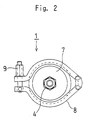
- Fig. 2 is a side view of the chemical filter in Fig. 1;
- Fig. 3 is an exploded perspective view of the chemical filter in Fig. 1;
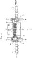
- Fig. 4 is a half-sectional view of the chemical filter in Fig. 1;
- Fig. 5 is an illustration of a baking system;
- Fig. 6 is a flow diagram showing a method for measuring the out-gas discharged from an O-ring;
- Fig. 7 is a flow diagram showing a method for measuring an ammonia removal efficiency; and
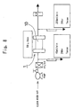
- Fig. 8 is a flow diagram showing a method for measuring an organic-matter removal efficiency.
-
- The chemical filter according to a preferred embodiment of the present invention is illustrated in Figs. 1 to 4. A
chemical filter 1 is provided within a flow passage (an air line of semiconductor manufacturing system or the like) of a gas to be treated (air, nitrogen gas or the like). A gas adsorbent 2 is housed in thechemical filter 1 and enclosed by a nonwoven fabric 3 (see Fig 4). Aplug 4 connects thechemical filter 1 to the passage. - As clearly shown in Fig. 4, the gas adsorbent 2 includes a plurality of different types of adsorbents, layered in the gas flow direction, enabling the removal of various types of gases. A first single-layer adsorbent 2a is provided for adsorbing alkali-based gases, a triply-layer adsorbent 2b is for adsorbing organic gases, and a second single-layer adsorbent 2c is for adsorbing acidic gases.
- Opening/
closing members 7 for replacing gas adsorbents 2 are provided at the both ends (the upstream and down stream ends) of aunit body 10 and fixed with theunit body 10 byrespective clamps 8. Eachclamp 8 is fixed by ahexagon nut 9. O-rings 11 (trademark: VITON ) made of fluorocarbon rubber are respectively provided between the upstream and downstream opening/closing members 7 made of SUS and theunit body 10 also made of SUS. - As clearly shown in Figs. 3 and 4, a
baffle member 12 is provided at the upstream side of the gas adsorbent 2 in thechemical filter 1, and a lath net is provided at the downstream side of the adsorbent 2 as aspacer 13. - Since the opening/
closing member 7 for changing the adsorbents 2 is fixed with theunit body 10 by theclamp 8, there is no need to use a bolt for fixing the opening/closing members 7. Thus, thechemical filter 1 may advantageously suppress the production of out-gas. The opening/closing member 7 is detachable from the unit body by a single manipulation of theclamp 8, allowing for easy washing and cleaning. - A
baffle member 12 is provided at the upstream side of the gas adsorbent 2 in thechemical filter 1. Therefore, incoming gas collides with thebaffle member 12 and diffuses before reaching at the gas adsorbent 2. As a result, the incoming gas is advantageously led to pass uniformly through the whole adsorbent 12. - A
spacer 13 is provided at the downstream side of the gas adsorbent 2 in thechemical filter 1. Thespacer 13 forms a space 14 (see Fig. 4). Therefore, the gas coming in through theplug 4 is advantageously prevented from passing through only the central area of the gas adsorbent 2 but allowed to uniformly pass through the overall adsorbent 2. - The gas flow rate in the
chemical filter 1, having a cylindrical shape, was 50 l/min, and the pressure loss was about 30 Pa. The pressure loss of the chemical filter was not very large in comparison with that of a pipe connected to the filter. - The chemical filter of the present invention is further described specifically below.
- The
unit body 10 was cleaned and baked as described below. - The
unit body 10, on which oil or the like adhered under metal machining process, was degreased and cleaned by being soaked in a sodium-hydroxide (NaOH) solution (at the temperature of 70 to 80°C) for 20 minutes, washed with flowing water, soaked in a hydrofluoric-acid nitrate solution for 5 to 6 hours, washed with flowing water, soaked in trichloroethylene for 3 to 5 minutes, dried at the temperature of 40 to 85°C, subsequently again soaked in IPA (isopropyl alcohol) for 6 hours, and then finally naturally dried. - The
unit body 10 was, in addition to the treatment in the comparative example 1 stated above, further ultrasonic-cleaned by demineralized water (resistance value: 18 MΩcm; the same was applied to the following embodiments) and subsequently by IPA (a special class: the same was applied to the following embodiments) as a solvent for 10 minutes respectively. - Then, as shown in Fig. 5, the cleaned
unit body 10 was put in a housing vessel made of SUS (capacity of 5 l) and baked in a heated oven for 30 minutes at a temperature of 50°C with a flow at 5l/min of clean air (obtained by passing compressed air through silica gel, an air filter or a chemical filter) or an inert gas (obtained by passing nitrogen gas having a purity of 99.999% or higher through a chemical filter). Then, the oven being stopped, theunit body 10 was cooled for 30 minutes with a flow of clean air. - The
unit body 10 was treated by the same process as in the comparative example 2, except the 30-minute baking was conducted at a temperature of 150°C, instead of 50°C. - The
unit body 10 was treated by the same process as in the comparative example 2, except for the ultrasonic cleaning was conducted with IPA and then with demineralized water, and the 30-minute baking was conducted at a temperature of 200°C. - The out-gas of the comparative examples 1 and 2 and the
embodiments 1 and 2 was evaluated as described below. - Each unit body was put in an SUS housing vessel and heated in an oven up to 50°C while supplying clean air at 2 to 300 ml/min. The air was collected with a Tenax collection tube (a filler for adsorbing gas, Tenax (trademark) GR, was used).
- The collected air was condensed by a thermal-desorption cold trap injector (TCT)(Model CP4020 made by GL Sciences Inc.) and analyzed by a gas·chromatographic mass spectroscope GC-MS (Model MD800 made by Thermo Quest K.K.). In accordance with the area of the chromatographic chart, the area was converted into the quantity of toluene and determined. And the determined quantity of toluene was divided by the sampled quantity to calculate the concentration of the out-gas in the air. The results are shown below.
- The toluene-converted value TOC of collected acetic acid, diethylene glycol and decanal (the out-gas) exhibited 0.193 µg/hr.
- The toluene-converted value TOC of collected IPA showed 26.845 µg/hr. This seems that IPA used for cleaning at the temperature of 50°C was left. IPA has a boiling point of 82.4°C.
- There was not any particularly high peak in the chromatographic chart and the toluene-converted value TOC showed 0.022 µg/hr. IPA was hardly left through heating at 150°C and cleaned up to about 1/10 of the comparative example 1.
- There was not any particularly high peak in the chromatographic chart and the toluene-converted value TOC showed 0.023 µg/hr. The same effect as in heating at 150°C was obtained by heating at 200°C.
- It is preferable to use a material causing a minimum quantity of out-gas for the sealed portion of a chemical filter. The sealed portion may be an O-
ring 11 of a normal product (a primary vulcanized product) made of chloroprene rubber, EPT or fluorocarbon rubber (trademark: VITON). However, in the viewpoint of reduction of out-gas, a secondary vulcanized product of fluorocarbon rubber (trademark: VITON ) is preferable for the sealed portion. - That is, as shown in Fig. 6, an O-
ring 11 of a primary vulcanized product and that of a secondary vulcanized product, both made of fluorocarbon rubber (trademark: VITON ), were respectively put in SUS chambers, heated for 1 hour at the temperature of 50°C Tenax (trademark) tubes in which respective out-gases were sampled were mounted to a TCT to qualitatively and quantitatively measure the out-gases by the GC-MS. - As a result, the out-gas of the primary vulcanized product of the O-
ring 11 made of fluorocarbon rubber (trademark: VITON ) showed 0.165 µg/g·hr, while the out-gas of the secondary vulcanized product showed 0.002 µg/g·hr. - Ammonia removal efficiency of
chemical filter 1 was measured using theunit body 10 of the embodiment 2. - As shown in Fig. 7, air was supplied to the
chemical filter 1. Air at the upstream and downstream sides was sampled through demineralized-water bubbling to measure the concentration of ammonia in the water by an ion chromatograph. The ion chromatography Model DX·100 made by NIPPON DIONEX CO., LTD was used as an analyzer. - As a result, the concentration of ammonia in the chemical filter at the upstream side showed 3.75 µg/m3, while that at the downstream side was decreased to 0.26 µg/m3, and the removal efficiency showed 93%.
- An organic-matter removal efficiency of the
chemical filter 1 was measured using theunit body 10 of the embodiment 2. - As shown in Fig. 8, the organic-matter concentration was measured by supplying air to the
chemical filter 1 and sampling air at the upstream and downstream sides by Tenax (trademark) tubes. The flow rate of air supplied to thechemical filter 1 was set to 50 l/min. - The TOC (toluene-converted value) concentration at the upstream side of the
chemical filter 1 showed 357.8 µg/m3, while that at the downstream side was decreased to 1.22 µg/m3, and the removal efficiency showed 99.7%. - Moreover, the concentration from xylene downward showed 296.3 µg/m3 at the upstream side of the chemical filter, while that at the downstream side was decreased to less than 0.01 µg/m3, and the removal efficiency showed 99.99% or more.
- The above measurement results prove that the amount of out-gas discharged from the unit body is decreased through cleaning the unit body. By passing the out-gas through the chemical filter, it is possible to supply a gas in which concentration of organic-matter gases, having a boiling point of 150°C or higher, and that of ammonia were respectively about 1 ppb (v) or less.
- Being composed as stated above, the present invention can supply a purified gas having a level lower than that causes troubles by contamination. Therefore, it is possible to provide a chemical filter capable of decreasing the troubles encountered in the conventional chemical filters in the semiconductor manufacturing systems.
Claims (5)
- A chemical filter comprising:a unit body;an adsorbent housed in said unit body; andsaid adsorbent adsorbing a gas, thereby allowing said chemical filter to supply an output gas having a concentration of ammonia of about 1 ppb(v) or less, and a concentration of an organic gas having a boiling point of about 150°C or higher of about 1 ppb(v) or less.
- A chemical filter according to Claim 1, wherein said unit body is cleaned and treated by at least one of an organic solvent and demineralized water, and then baked at a temperature of about 100 to 300°C with receiving a continuous flow of a clean gas.
- A chemical filter according to Claim 2, wherein said unit body is, after being baked, cooled with a flow of a clean air.
- A chemical filter according to any one of Claims 1 to 3, further comprising:an opening/closing section on said unit body for replacing adsorbents, said opening/closing section being fixed by a clamp;a baffle member at an upstream side of said adsorbent;a spacer at a downstream side of said adsorbent; anda seal section using vulcanized fluorocarbon rubber.
- A chemical filter according to any one of Claims 1 to 4, wherein said chemical filter is sealed and packaged in a vacuum-deaerated bag made of aluminum laminate.
Applications Claiming Priority (2)
| Application Number | Priority Date | Filing Date | Title |
|---|---|---|---|
| JP2000303884 | 2000-10-03 | ||
| JP2000303884A JP2002102638A (en) | 2000-10-03 | 2000-10-03 | Chemical filter |
Publications (1)
| Publication Number | Publication Date |
|---|---|
| EP1195188A1 true EP1195188A1 (en) | 2002-04-10 |
Family
ID=18785020
Family Applications (1)
| Application Number | Title | Priority Date | Filing Date |
|---|---|---|---|
| EP01308415A Withdrawn EP1195188A1 (en) | 2000-10-03 | 2001-10-02 | Chemical filter |
Country Status (6)
| Country | Link |
|---|---|
| US (1) | US20020014160A1 (en) |
| EP (1) | EP1195188A1 (en) |
| JP (1) | JP2002102638A (en) |
| KR (1) | KR20020026825A (en) |
| CN (1) | CN1357403A (en) |
| SG (1) | SG101489A1 (en) |
Cited By (1)
| Publication number | Priority date | Publication date | Assignee | Title |
|---|---|---|---|---|
| US7132011B2 (en) | 2003-09-02 | 2006-11-07 | Entegris, Inc. | Reactive gas filter |
Families Citing this family (4)
| Publication number | Priority date | Publication date | Assignee | Title |
|---|---|---|---|---|
| WO2004113870A2 (en) * | 2003-06-18 | 2004-12-29 | The Johns Hopkins University | Time domain resolving chemical sampler using sorbent material |
| JP5613367B2 (en) * | 2008-01-18 | 2014-10-22 | 大日商事株式会社 | Chemical filter and its packing body and reticle storage box |
| CN110694424B (en) * | 2019-09-25 | 2023-04-07 | 浙江新环合成材料有限公司 | Harmful gas filtration equipment for chemical industry pharmacy |
| WO2023186404A1 (en) * | 2022-03-29 | 2023-10-05 | Zf Cv Systems Europe Bv | Air-dryer cartridge, air supply unit, pneumatic system and vehicle |
Citations (4)
| Publication number | Priority date | Publication date | Assignee | Title |
|---|---|---|---|---|
| US3961920A (en) * | 1974-01-24 | 1976-06-08 | Humphrey Gilbert | Gas adsorber cell test sampler |
| EP1022043A1 (en) * | 1998-08-05 | 2000-07-26 | Toray Industries, Inc. | Chemical filter unit and gas purification system |
| US6113674A (en) * | 1997-07-11 | 2000-09-05 | Donaldson Company, Inc. | Adsorption apparatus and methods |
| EP1121968A2 (en) * | 2000-01-31 | 2001-08-08 | Nichias Co., Ltd. | Chemical filter and manufacturing method thereof |
Family Cites Families (1)
| Publication number | Priority date | Publication date | Assignee | Title |
|---|---|---|---|---|
| JP3977514B2 (en) * | 1998-05-26 | 2007-09-19 | 高砂熱学工業株式会社 | Air purification filter, method of manufacturing the same, and advanced cleaning device |
-
2000
- 2000-10-03 JP JP2000303884A patent/JP2002102638A/en active Pending
-
2001
- 2001-09-27 KR KR1020010059910A patent/KR20020026825A/en not_active Withdrawn
- 2001-10-02 EP EP01308415A patent/EP1195188A1/en not_active Withdrawn
- 2001-10-03 US US09/969,693 patent/US20020014160A1/en not_active Abandoned
- 2001-10-03 SG SG200106132A patent/SG101489A1/en unknown
- 2001-10-03 CN CN01130322A patent/CN1357403A/en active Pending
Patent Citations (4)
| Publication number | Priority date | Publication date | Assignee | Title |
|---|---|---|---|---|
| US3961920A (en) * | 1974-01-24 | 1976-06-08 | Humphrey Gilbert | Gas adsorber cell test sampler |
| US6113674A (en) * | 1997-07-11 | 2000-09-05 | Donaldson Company, Inc. | Adsorption apparatus and methods |
| EP1022043A1 (en) * | 1998-08-05 | 2000-07-26 | Toray Industries, Inc. | Chemical filter unit and gas purification system |
| EP1121968A2 (en) * | 2000-01-31 | 2001-08-08 | Nichias Co., Ltd. | Chemical filter and manufacturing method thereof |
Cited By (1)
| Publication number | Priority date | Publication date | Assignee | Title |
|---|---|---|---|---|
| US7132011B2 (en) | 2003-09-02 | 2006-11-07 | Entegris, Inc. | Reactive gas filter |
Also Published As
| Publication number | Publication date |
|---|---|
| KR20020026825A (en) | 2002-04-12 |
| US20020014160A1 (en) | 2002-02-07 |
| JP2002102638A (en) | 2002-04-09 |
| SG101489A1 (en) | 2004-01-30 |
| CN1357403A (en) | 2002-07-10 |
Similar Documents
| Publication | Publication Date | Title |
|---|---|---|
| JP5049214B2 (en) | System and method for measuring and managing contaminants | |
| US7314506B2 (en) | Fluid purification system with low temperature purifier | |
| US7092077B2 (en) | System and method for monitoring contamination | |
| JP4729483B2 (en) | Method for removing airborne molecular contaminants using oxygen and / or water gas mixtures | |
| JP2001503840A (en) | Gas panel | |
| JP2003532034A5 (en) | ||
| EP1670566A1 (en) | Reactive gas filter | |
| US20040023419A1 (en) | System and method for monitoring contamination | |
| US20020014160A1 (en) | Chemical Filter | |
| US20070144118A1 (en) | Purging of a wafer conveyance container | |
| JPH06205971A (en) | Method and system for purification of gas | |
| KR102615911B1 (en) | Vacuum actuator containment for mitigation of molecular contaminants and particles | |
| RU2013128394A (en) | FILTER DEVICE AND METHOD FOR CLEANING GAS FLOW | |
| JP2001124748A (en) | High-speed analysis method and apparatus for chlorobenzene | |
| US20180369740A1 (en) | High Purity Gas Purifier | |
| CN212379130U (en) | Device for measuring concentration lower than gas detection limit | |
| JP5126192B2 (en) | Fluid purification device | |
| JP4044851B2 (en) | Method for measuring volatile organic substances and sampling instrument for measurement | |
| JP4447213B2 (en) | Fluid purification device | |
| DK1509299T3 (en) | Method and device for purifying air | |
| KR20230144254A (en) | A gas management system including a gas recycling system and a gas analysis system | |
| TH56873A (en) | Chemical filter | |
| Gronheid et al. | In-line monitoring of acid and base contaminants at low ppt levels for 193nm lithography |
Legal Events
| Date | Code | Title | Description |
|---|---|---|---|
| PUAI | Public reference made under article 153(3) epc to a published international application that has entered the european phase |
Free format text: ORIGINAL CODE: 0009012 |
|
| AK | Designated contracting states |
Kind code of ref document: A1 Designated state(s): AT BE CH CY DE DK ES FI FR GB GR IE IT LI LU MC NL PT SE TR Kind code of ref document: A1 Designated state(s): DE SE |
|
| AX | Request for extension of the european patent |
Free format text: AL;LT;LV;MK;RO;SI |
|
| 17P | Request for examination filed |
Effective date: 20020724 |
|
| AKX | Designation fees paid |
Free format text: DE SE |
|
| STAA | Information on the status of an ep patent application or granted ep patent |
Free format text: STATUS: THE APPLICATION HAS BEEN WITHDRAWN |
|
| 18W | Application withdrawn |
Effective date: 20030521 |