EP1195120A1 - Appareil électroménager comprenant un élément mobile apte à être mis en place de façon amovible sur un socle - Google Patents
Appareil électroménager comprenant un élément mobile apte à être mis en place de façon amovible sur un socle Download PDFInfo
- Publication number
- EP1195120A1 EP1195120A1 EP01420192A EP01420192A EP1195120A1 EP 1195120 A1 EP1195120 A1 EP 1195120A1 EP 01420192 A EP01420192 A EP 01420192A EP 01420192 A EP01420192 A EP 01420192A EP 1195120 A1 EP1195120 A1 EP 1195120A1
- Authority
- EP
- European Patent Office
- Prior art keywords
- base
- mobile element
- duty cycle
- household appliance
- signal
- Prior art date
- Legal status (The legal status is an assumption and is not a legal conclusion. Google has not performed a legal analysis and makes no representation as to the accuracy of the status listed.)
- Granted
Links
Images


Classifications
-
- H—ELECTRICITY
- H05—ELECTRIC TECHNIQUES NOT OTHERWISE PROVIDED FOR
- H05B—ELECTRIC HEATING; ELECTRIC LIGHT SOURCES NOT OTHERWISE PROVIDED FOR; CIRCUIT ARRANGEMENTS FOR ELECTRIC LIGHT SOURCES, IN GENERAL
- H05B1/00—Details of electric heating devices
- H05B1/02—Automatic switching arrangements specially adapted to apparatus ; Control of heating devices
- H05B1/0227—Applications
- H05B1/0252—Domestic applications
- H05B1/0258—For cooking
- H05B1/0269—For heating of fluids
-
- A—HUMAN NECESSITIES
- A47—FURNITURE; DOMESTIC ARTICLES OR APPLIANCES; COFFEE MILLS; SPICE MILLS; SUCTION CLEANERS IN GENERAL
- A47J—KITCHEN EQUIPMENT; COFFEE MILLS; SPICE MILLS; APPARATUS FOR MAKING BEVERAGES
- A47J27/00—Cooking-vessels
- A47J27/21—Water-boiling vessels, e.g. kettles
- A47J27/21008—Water-boiling vessels, e.g. kettles electrically heated
- A47J27/2105—Water-boiling vessels, e.g. kettles electrically heated of the cordless type, i.e. whereby the water vessel can be plugged into an electrically-powered base element
-
- H—ELECTRICITY
- H05—ELECTRIC TECHNIQUES NOT OTHERWISE PROVIDED FOR
- H05B—ELECTRIC HEATING; ELECTRIC LIGHT SOURCES NOT OTHERWISE PROVIDED FOR; CIRCUIT ARRANGEMENTS FOR ELECTRIC LIGHT SOURCES, IN GENERAL
- H05B3/00—Ohmic-resistance heating
- H05B3/78—Heating arrangements specially adapted for immersion heating
- H05B3/82—Fixedly-mounted immersion heaters
Definitions
- the invention relates to the field of household appliances. It aims more precisely household appliances with a movable element removable in a base, in which information must be transmitted from the mobile part to the base. It relates more specifically the design of the electronic means which ensure the transmission of this information from the mobile element to the base with a high level of reliability and a low cost price.
- the heating resistance is supplied by a connector located at the contact area between the pot and the base.
- This connector typically comprises three poles, namely a phase, a neutral and an earth.
- the fact that the electronic box is located inside the pot removable requires perfect sealing to prevent electronics from being damaged by water infiltration, especially during cleaning.
- the presence of a heating element near the module electronics induces thermal stresses on the latter. Consequently, the cost price of such a solution is relatively high.
- the electronic module can be associated with a thermistor which performs a double function.
- This thermistor can measure both the water temperature and quickly detect the overheating of the heating element when there is no water in the pot.
- This thermistor is housed so as to be influenced by water temperature when this is present, and by the temperature of the heating element in absence of water.
- the electrical contacts through which information is transmitted between the pot and the base are subject to possible oxidation phenomena which modify its impedance.
- a thermistor located in the pot which would be linked to the base via a connector, would deliver a random information, depending on the oxidation state of the connector.
- Such mounting will of course be unusable for optimized regulation.
- An object of the invention is to allow the equipment of a kettle wireless, or more generally of a device comprising a mobile element and removable from a base, with a device allowing an exchange of information the element movable towards the base, which is of particularly reduced cost, reliable and robust.
- the invention therefore relates to a household appliance, which comprises a mobile element capable of being removably placed on a base, in which the movable element comprises an electric heating resistor supplied by a source of electrical energy associated with the base via a connector located in the contact area between the movable element and the base, and in which a signal representative of a physical quantity of the mobile element is transmitted from the movable element towards the base.
- the movable element comprises analog electronic means including a duty cycle generator variable according to information representative of a physical quantity of the movable element.
- the mobile element is equipped with a heating resistance powered by a power circuit, and includes an electronic module which transmits, to the base, information of the variable duty cycle type, developed from particularly simple amplifier-type components operational, excluding any digital component.
- the signal can be sent from the mobile element to the base under various forms. It can be an infrared optical transmission by example, or a radio link, or even a transmission electrical, by a connection of the conductive contact type.
- the transmission of information of the variable cyclic type is particularly advantageous since it is insensitive to phenomena that may appear due to a weakened transmission, or a poor conductor contact.
- the temperature drifts undergone by the components stakeholders in the variable duty cycle generator are not detrimental to the quality of the information transmitted, since the information is not not measured in relation to absolute times, but in relation to times which derive the same way.
- the pot also comprises a module packaging electronics delivering to the duty cycle generator variable, a voltage depending on the physical quantity of the mobile element measured.
- the electronic means comprise a stage amplifier which conditions the signal coming from the organ sensitive to the variation in temperature, so the duty cycle generator is voltage controlled.
- the duty cycle generator attacks a transmission module which processes the signal which will be transmitted to the destination of the base.
- the transmission module can include an optoelectronic component, controlled by the signal from the variable duty cycle generator, for signal transmission optics from the movable element to the base.
- It may for example be a light-emitting or infrared diode associated with a transistor controlled by the signal from the report generator cyclic variable, adapted in impedance.
- the transmission module can have a connection pin controlled by the signal from the variable duty cycle generator, for current transmission electric from the movable element to the base.
- variable duty cycle signal is transmitted by a electric current between the movable element and the base, using a pin additional to the power connector, in combination with the terminal ground of this same power connector.
- the transmission module may include a radio transmitter controlled by the signal from the duty cycle generator, for the transmission to the base of radio waves of frequency between a few tens of kiloHertz and the gigaHertz.
- the conditioning module is connected to a thermistor sensitive to the temperature of one or more organs of the movable element.
- the variation in resistance of the thermistor as a function of the temperature generates a variable voltage depending on the temperature, this voltage then controlling the report generator variable cyclic.
- the different stages constituted by the variable duty cycle generator, conditioning modules and transmission each have an operational amplifier, these operational amplifiers all belonging to a single box.
- the electronic means on board the mobile element have only one active component and a large number of passive components.
- Such a kettle has a base (1) on which can be placed a removable pot (2).
- This pot has a gripping area (3).
- the pot (2) also includes a heating resistor (4) located at near the bottom of the pot.
- This heating resistor (4) is connected to a connector (5) located on the pot area opposite the base (1).
- This connector (5) has three poles, namely a mass, a phase, and an earth. This connector (5) allows the heating resistance (4) to be supplied from the line voltage.
- the base (1) comprises a power cord (7).
- the base (1) comprises an electronic module (8) capable of regulating the supply of the electrical resistance (4), as well as a protective function.
- the electronic module (8) can thus supply the heating resistance (4) via contactors (9) appropriately controlled.
- the pot (2) is equipped with electronic means specific (10) intended to ensure the transmission of information relating to the temperature of the water (or the heating element of the pot), towards the base and to the regulating means (8).
- the means electronic components (10) have components in the illustrated form optoelectronics ensuring the transmission of an infrared signal from the face bottom of the pot towards the area opposite the base.
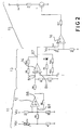
- the electronic means (10) on board the pot mobile are illustrated in Figure 2.
- These means include a stage of packaging (11) comprising an operational amplifier (12) looped over its inverting input B9, and which delivers a voltage as a function of the value of the NTC resistance, itself sensitive to the temperature of its vicinity.
- the electronic means (10) on board the pot include a duty cycle generator (13).
- This generator duty cycle (13) includes an operational amplifier (14) looped over its non-inverting input B5, as well as a capacitor C1, one terminal of which is connected to ground, the other terminal being connected to the inverting input B6 of the operational amplifier (14).
- variable duty cycle generator The operation of the variable duty cycle generator is as follows. When the capacitor C1 is discharged, and the voltage on the inverting terminal B6 of the operational amplifier (14) is lower than the voltage present on the inverting terminal B5, the output terminal B7 of the operational amplifier (14) is at a potential close to the supply voltage V dc (for example + 12V).
- V dc the supply voltage
- the voltage on the non-inverting terminal B5 is determined as a function of the output voltage B8 of the conditioning stage, the supply voltage V cc and the various resistors (R6, R7, R71, R8 and R81).
- the capacitor C1 charges through the resistors R9 and R10, R10 in parallel, the diode D1 being conductive. Capacity C1 is charged until the voltage across its terminals reaches the potential present on the terminal non-inverting B5. At this time, the output B7 of the operational amplifier (14) goes to a potential close to 0, which on the one hand modifies the voltage at level of the non-inverting terminal B5, and blocks the conduction of the diode D1.
- the capacitor C1 is then discharged through the resistors R10 and R101, and the value of the voltage on the non-inverting terminal B5 of the amplifier operational (14) goes to a lower value, depending on the output voltage B8 of the conditioning stage (11), and of the different resistances R6, R7, R8 related to it.
- the voltage at output B7 of the operational amplifier (14) remains at one low value as long as the voltage across capacitance C1 remains higher at the potential present on the non-inverting terminal B5.
- the chronogram of the FIG. 4 illustrates the charging (20) and discharging (21) phases of the capacity.
- the capacity C1 is used when the output voltage B7 operational amplifier (14) either high or low. This means that any drifts due to the temperature or the accuracy of this capacity, which modify the charging time, are identical for high times and low time of the variable duty cycle signal. The relationship between times highs and low times is therefore unchanged according to this drift in temperature.
- the duty cycle generator (13) supplies a transmission stage (15) comprising an operational amplifier (16) acting as a comparator, and controlling a transistor T1.
- the light-emitting diode D4 is traversed by a current, and therefore emits the signal of variable duty cycle in plinth direction.
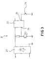
- the electronic means (8) receiving the signal from of the pot are illustrated in FIG. 3.
- These electronic means (8) include a continuous power supply (27) and a microcontroller (22) having multiple inputs and outputs.
- This microcontroller (22) has inputs logic, corresponding to the state of push buttons (26) or the like located on the base (1). It should be noted that thanks to this arrangement there is no need have push buttons on the mobile pot (2), which reduces the sealing constraints of the pot (2).
- Another of these inputs (24) is connected to a sensitive T2 phototransistor to the beam from the mobile pot (2).
- the variable duty cycle signal is therefore analyzed by the microcontroller (22).
- the microcontroller (22) is capable of determining the temperature of the water present in the pot, or else another overheating of the heating resistance due to the absence of water.
- the microcontroller (22) is able to control contactors or relays (9) supplying power to the heating resistance (4).
- the invention is in no way limited to the illustrated form, and also covers variants in which the duty cycle signal is not transmitted in optical form, but directly by a contact electric, or a radio wave.
- the invention also covers other types of devices such as in particular wax epilators, coffee makers, teapots, cooking appliances or irons.
- the devices according to the invention have the important advantage of ensuring optimum reliability by using a very limited number of active components on board the mobile pot.
- the electronic assembly used is relatively insensitive to drifts in temperature, or the accuracy of the components used.
Landscapes
- Engineering & Computer Science (AREA)
- Food Science & Technology (AREA)
- Cookers (AREA)
- Brushes (AREA)
- Control Of Temperature (AREA)
- Food-Manufacturing Devices (AREA)
- Switches With Compound Operations (AREA)
- Dry Shavers And Clippers (AREA)
- Connector Housings Or Holding Contact Members (AREA)
Abstract
Description
Claims (8)
- Appareil électroménager, comprenant un élément mobile (2) apte à être mis en place de façon amovible sur un socle (1), dans lequel l'élément mobile (2) comporte une résistance électrique chauffante (4) alimentée par une source d'énergie électrique associée au socle (1) via un connecteur (5) situé dans la zone de contact entre l'élément mobile (2) et le socle (1), et dans lequel un signal représentatif d'une grandeur physique de l'élément mobile (2) est transmis de l'élément mobile (2) vers le socle (1), caractérisé en ce que l'élément mobile (2) comprend des moyens électroniques analogiques (10) incluant un générateur de rapport cyclique variable (13) en fonction d'une information représentative d'une grandeur physique de l'élément mobile (2).
- Appareil électroménager selon la revendication 1, caractérisé en ce qu'il comporte un module électronique de conditionnement (11), délivrant au générateur de rapport cyclique variable (13) une tension fonction de la grandeur physique de l'élément mobile (2).
- Appareil électroménager selon la revendication 2, caractérisé en ce que le module de conditionnement est relié à une thermistance (CTN) sensible à la température d'un organe de l'élément mobile (2).
- Appareil électroménager selon la revendication 1, caractérisé en ce qu'il comporte un module de transmission (15) du signal issu du générateur de rapport cyclique variable (13).
- Appareil électroménager selon la revendication 4, caractérisé en ce que le module de transmission (15) comporte un composant opto-électronique (D4) commandé par le signal issu du générateur de rapport cyclique variable (13), en vue de l'émission d'un signal optique depuis l'élément mobile (2) vers le socle (1).
- Appareil électroménager selon la revendication 4, caractérisé en ce que le module de transmission comporte une broche de connexion alimentée par le signal issu du générateur de rapport cyclique variable, en vue de la transmission d'un courant depuis l'élément mobile vers le socle.
- Appareil électroménager selon la revendication 4, caractérisé en ce que le module de transmission comporte un émetteur radio commandé par le signal issu du générateur de rapport cyclique variable, en vue de l'émission d'ondes radio depuis l'élément mobile vers le socle.
- Appareil électroménager selon la revendication 2 et la revendication 3 ou 4, caractérisé en ce que le générateur de rapport cyclique variable (13), le module de conditionnement (11) et le module de transmission (15) comportent chacun un amplificateur opérationnel, les différents amplificateurs opérationnels étant contenus dans un même boítier électronique.
Applications Claiming Priority (2)
| Application Number | Priority Date | Filing Date | Title |
|---|---|---|---|
| FR0012691 | 2000-10-04 | ||
| FR0012691A FR2814657B1 (fr) | 2000-10-04 | 2000-10-04 | Appareil electromenager comprenant un element mobile apte a etre mis en place de facon amovible sur un socle |
Publications (2)
| Publication Number | Publication Date |
|---|---|
| EP1195120A1 true EP1195120A1 (fr) | 2002-04-10 |
| EP1195120B1 EP1195120B1 (fr) | 2004-09-29 |
Family
ID=8855003
Family Applications (1)
| Application Number | Title | Priority Date | Filing Date |
|---|---|---|---|
| EP01420192A Expired - Lifetime EP1195120B1 (fr) | 2000-10-04 | 2001-09-11 | Appareil électroménager comprenant un élément mobile apte à être mis en place de façon amovible sur un socle |
Country Status (5)
| Country | Link |
|---|---|
| EP (1) | EP1195120B1 (fr) |
| AT (1) | ATE277550T1 (fr) |
| DE (1) | DE60105933T2 (fr) |
| FR (1) | FR2814657B1 (fr) |
| HK (1) | HK1045798A1 (fr) |
Cited By (4)
| Publication number | Priority date | Publication date | Assignee | Title |
|---|---|---|---|---|
| GB2435811A (en) * | 2006-03-08 | 2007-09-12 | Otter Controls Ltd | Control for cordless electrical appliance |
| CN102160013A (zh) * | 2007-06-18 | 2011-08-17 | 奥特控制有限公司 | 液体加热容器及其控制器 |
| CN103519682A (zh) * | 2012-07-06 | 2014-01-22 | 四川蓝讯宝迩电子科技有限公司 | 防干烧无线电水壶 |
| CN105496194B (zh) * | 2007-05-25 | 2019-02-19 | 布瑞威利私人有限公司 | 电壶系统 |
Families Citing this family (3)
| Publication number | Priority date | Publication date | Assignee | Title |
|---|---|---|---|---|
| GB2421423B (en) * | 2004-12-23 | 2008-08-27 | Roger Payn | Appliances for heating and cooling liquids |
| CN105982535A (zh) * | 2015-01-28 | 2016-10-05 | 广东美的生活电器制造有限公司 | 无绳液体加热装置 |
| WO2025171034A1 (fr) * | 2024-02-06 | 2025-08-14 | Baxter International Inc. | Récipient de chauffage de solution |
Citations (6)
| Publication number | Priority date | Publication date | Assignee | Title |
|---|---|---|---|---|
| US3742178A (en) * | 1971-12-29 | 1973-06-26 | Gen Electric | Induction cooking appliance including cooking vessel having means for wireless transmission of temperature data |
| US3742174A (en) * | 1971-12-29 | 1973-06-26 | Gen Electric | Induction cooking appliance including cooking vessel having means for transmission of temperature data by light pulses |
| GB2145245A (en) * | 1983-07-08 | 1985-03-20 | Sanyo Electric Co | Induction heating cooking apparatus |
| DE3836099A1 (de) * | 1988-10-22 | 1990-05-10 | Asea Brown Boveri | Fernmesseinrichtung zur messung und uebertragung verschiedener daten innerhalb eines kochtopfes |
| EP0380369A1 (fr) * | 1989-01-26 | 1990-08-01 | Otter Controls Limited | Commande pour éléments chauffants à alimentation électrique |
| DE29809392U1 (de) * | 1998-05-26 | 1998-08-20 | Ego Elektro Geraetebau Gmbh | Anordnung zur Temperaturerfassung eines Kochbehälters für die Regelung einer Heizeinrichtung für den Kochbehälter |
-
2000
- 2000-10-04 FR FR0012691A patent/FR2814657B1/fr not_active Expired - Fee Related
-
2001
- 2001-09-11 DE DE60105933T patent/DE60105933T2/de not_active Expired - Lifetime
- 2001-09-11 AT AT01420192T patent/ATE277550T1/de not_active IP Right Cessation
- 2001-09-11 EP EP01420192A patent/EP1195120B1/fr not_active Expired - Lifetime
-
2002
- 2002-10-03 HK HK02107261.5A patent/HK1045798A1/zh unknown
Patent Citations (6)
| Publication number | Priority date | Publication date | Assignee | Title |
|---|---|---|---|---|
| US3742178A (en) * | 1971-12-29 | 1973-06-26 | Gen Electric | Induction cooking appliance including cooking vessel having means for wireless transmission of temperature data |
| US3742174A (en) * | 1971-12-29 | 1973-06-26 | Gen Electric | Induction cooking appliance including cooking vessel having means for transmission of temperature data by light pulses |
| GB2145245A (en) * | 1983-07-08 | 1985-03-20 | Sanyo Electric Co | Induction heating cooking apparatus |
| DE3836099A1 (de) * | 1988-10-22 | 1990-05-10 | Asea Brown Boveri | Fernmesseinrichtung zur messung und uebertragung verschiedener daten innerhalb eines kochtopfes |
| EP0380369A1 (fr) * | 1989-01-26 | 1990-08-01 | Otter Controls Limited | Commande pour éléments chauffants à alimentation électrique |
| DE29809392U1 (de) * | 1998-05-26 | 1998-08-20 | Ego Elektro Geraetebau Gmbh | Anordnung zur Temperaturerfassung eines Kochbehälters für die Regelung einer Heizeinrichtung für den Kochbehälter |
Cited By (7)
| Publication number | Priority date | Publication date | Assignee | Title |
|---|---|---|---|---|
| GB2435811A (en) * | 2006-03-08 | 2007-09-12 | Otter Controls Ltd | Control for cordless electrical appliance |
| CN105496194B (zh) * | 2007-05-25 | 2019-02-19 | 布瑞威利私人有限公司 | 电壶系统 |
| CN102160013A (zh) * | 2007-06-18 | 2011-08-17 | 奥特控制有限公司 | 液体加热容器及其控制器 |
| EP2661994A1 (fr) * | 2007-06-18 | 2013-11-13 | Otter Controls Limited | Récipient chauffant pour liquide et commande |
| EP2165243B1 (fr) * | 2007-06-18 | 2014-02-12 | Otter Controls Limited | Récipient chauffant pour liquide et commande |
| CN102160013B (zh) * | 2007-06-18 | 2014-03-26 | 翱泰温控器(深圳)有限公司 | 液体加热容器及其控制器 |
| CN103519682A (zh) * | 2012-07-06 | 2014-01-22 | 四川蓝讯宝迩电子科技有限公司 | 防干烧无线电水壶 |
Also Published As
| Publication number | Publication date |
|---|---|
| ATE277550T1 (de) | 2004-10-15 |
| DE60105933T2 (de) | 2005-10-13 |
| FR2814657A1 (fr) | 2002-04-05 |
| EP1195120B1 (fr) | 2004-09-29 |
| HK1045798A1 (zh) | 2002-12-13 |
| FR2814657B1 (fr) | 2003-06-13 |
| DE60105933D1 (de) | 2004-11-04 |
Similar Documents
| Publication | Publication Date | Title |
|---|---|---|
| CA1294326C (fr) | Controleur electronique alimente pendant les periodes inactives de commutation du secteur | |
| FR2635911A1 (fr) | Module auxiliaire - dispositif de commande pour disjoncteur en boitier moule | |
| WO2007110493A2 (fr) | Appareil de preparation culinaire muni d'un disposititif de securite | |
| FR2794334A1 (fr) | Ballast pour lampe a decharge comportant un convertisseur de tension | |
| EP1195120B1 (fr) | Appareil électroménager comprenant un élément mobile apte à être mis en place de façon amovible sur un socle | |
| FR2526600A1 (fr) | Dispositif de securite destine a empecher la marche intempestive d'un appareil electrique lors de son branchement alors que son interrupteur de mise en marche est ferme | |
| FR2535000A1 (fr) | Embrayage electronique pour outils electriques a vitesse variable | |
| FR2571148A1 (fr) | Detecteur de faisceau lumineux a photodiode a circuit de reglage du point de fonctionnement | |
| FR2667924A1 (fr) | Procede de protection contre les surcharges d'appareils ne pouvant fonctionner en continu par suite de dissipation de chaleur. | |
| FR2846729A1 (fr) | Dispositif de protection et de securite programmable pour outils motorises | |
| WO1999029219A1 (fr) | Appareil electrique de cuisson a cuve amovible | |
| FR2774186A1 (fr) | Thermostat a thermistance et interrupteur-relais pour resistances chauffantes d'appareil electromenager | |
| FR2593637A1 (fr) | Dispositif de securite pour assurer la coupure automatique de l'alimentation electrique d'un appareil chauffant mobile, en particulier d'un fer a repasser | |
| EP3776617A1 (fr) | Dispositif électronique de coupure | |
| FR2793104A1 (fr) | Procede de pilotage d'un element chauffant d'appareil electrique de chauffage de liquide | |
| WO1999058754A1 (fr) | Fer a repasser electrique | |
| FR3020904A1 (fr) | Bloc d'alimentation de condensateur pour petits consommateurs electriques a besoin en courant eleve | |
| FR2571186A1 (fr) | Procede et dispositif de commande d'un moteur electrique a alimentation triphasee | |
| EP0412197B1 (fr) | Bloc individuel de jonction pour la compensation de soudure froide d'un couple thermoélectrique | |
| FR2951013A1 (fr) | Procede et dispositif de commutation d'un relais electromagnetique | |
| FR2810115A1 (fr) | Appareil de test des controleurs d'isolement de reseaux electriques | |
| EP3041010B1 (fr) | Dispositif et procédé de commande d'un relais électromécanique | |
| FR2956534A1 (fr) | Dispositif de maintien de l'alimentation d'un appareil electrique raccorde a un reseau electrique fonctionnant selon des periodes tarifaires par contacteur ou programmateur | |
| FR2848685A1 (fr) | Radiateur a inertie et son procede d'alimentation en courant | |
| EP4059392A1 (fr) | Pince pour produits alimentaires pourvue d'un dispositif de mesure d'épaisseur d'aliment |
Legal Events
| Date | Code | Title | Description |
|---|---|---|---|
| PUAI | Public reference made under article 153(3) epc to a published international application that has entered the european phase |
Free format text: ORIGINAL CODE: 0009012 |
|
| AK | Designated contracting states |
Kind code of ref document: A1 Designated state(s): AT BE CH CY DE DK ES FI FR GB GR IE IT LI LU MC NL PT SE TR |
|
| AX | Request for extension of the european patent |
Free format text: AL;LT;LV;MK;RO;SI |
|
| 17P | Request for examination filed |
Effective date: 20020905 |
|
| AKX | Designation fees paid |
Free format text: AT BE CH CY DE DK ES FI FR GB GR IE IT LI LU MC NL PT SE TR |
|
| GRAP | Despatch of communication of intention to grant a patent |
Free format text: ORIGINAL CODE: EPIDOSNIGR1 |
|
| GRAS | Grant fee paid |
Free format text: ORIGINAL CODE: EPIDOSNIGR3 |
|
| GRAA | (expected) grant |
Free format text: ORIGINAL CODE: 0009210 |
|
| AK | Designated contracting states |
Kind code of ref document: B1 Designated state(s): AT BE CH CY DE DK ES FI FR GB GR IE IT LI LU MC NL PT SE TR |
|
| PG25 | Lapsed in a contracting state [announced via postgrant information from national office to epo] |
Ref country code: FI Free format text: LAPSE BECAUSE OF FAILURE TO SUBMIT A TRANSLATION OF THE DESCRIPTION OR TO PAY THE FEE WITHIN THE PRESCRIBED TIME-LIMIT Effective date: 20040929 Ref country code: TR Free format text: LAPSE BECAUSE OF FAILURE TO SUBMIT A TRANSLATION OF THE DESCRIPTION OR TO PAY THE FEE WITHIN THE PRESCRIBED TIME-LIMIT Effective date: 20040929 Ref country code: AT Free format text: LAPSE BECAUSE OF FAILURE TO SUBMIT A TRANSLATION OF THE DESCRIPTION OR TO PAY THE FEE WITHIN THE PRESCRIBED TIME-LIMIT Effective date: 20040929 Ref country code: IE Free format text: LAPSE BECAUSE OF FAILURE TO SUBMIT A TRANSLATION OF THE DESCRIPTION OR TO PAY THE FEE WITHIN THE PRESCRIBED TIME-LIMIT Effective date: 20040929 |
|
| REG | Reference to a national code |
Ref country code: GB Ref legal event code: FG4D Free format text: NOT ENGLISH |
|
| REG | Reference to a national code |
Ref country code: CH Ref legal event code: EP |
|
| REG | Reference to a national code |
Ref country code: IE Ref legal event code: FG4D Free format text: FRENCH |
|
| REF | Corresponds to: |
Ref document number: 60105933 Country of ref document: DE Date of ref document: 20041104 Kind code of ref document: P |
|
| PG25 | Lapsed in a contracting state [announced via postgrant information from national office to epo] |
Ref country code: SE Free format text: LAPSE BECAUSE OF FAILURE TO SUBMIT A TRANSLATION OF THE DESCRIPTION OR TO PAY THE FEE WITHIN THE PRESCRIBED TIME-LIMIT Effective date: 20041229 Ref country code: DK Free format text: LAPSE BECAUSE OF FAILURE TO SUBMIT A TRANSLATION OF THE DESCRIPTION OR TO PAY THE FEE WITHIN THE PRESCRIBED TIME-LIMIT Effective date: 20041229 Ref country code: GR Free format text: LAPSE BECAUSE OF FAILURE TO SUBMIT A TRANSLATION OF THE DESCRIPTION OR TO PAY THE FEE WITHIN THE PRESCRIBED TIME-LIMIT Effective date: 20041229 |
|
| PG25 | Lapsed in a contracting state [announced via postgrant information from national office to epo] |
Ref country code: ES Free format text: LAPSE BECAUSE OF FAILURE TO SUBMIT A TRANSLATION OF THE DESCRIPTION OR TO PAY THE FEE WITHIN THE PRESCRIBED TIME-LIMIT Effective date: 20050109 |
|
| GBT | Gb: translation of ep patent filed (gb section 77(6)(a)/1977) |
Effective date: 20041216 |
|
| REG | Reference to a national code |
Ref country code: IE Ref legal event code: FD4D |
|
| PLBE | No opposition filed within time limit |
Free format text: ORIGINAL CODE: 0009261 |
|
| STAA | Information on the status of an ep patent application or granted ep patent |
Free format text: STATUS: NO OPPOSITION FILED WITHIN TIME LIMIT |
|
| PG25 | Lapsed in a contracting state [announced via postgrant information from national office to epo] |
Ref country code: CY Free format text: LAPSE BECAUSE OF FAILURE TO SUBMIT A TRANSLATION OF THE DESCRIPTION OR TO PAY THE FEE WITHIN THE PRESCRIBED TIME-LIMIT Effective date: 20050911 |
|
| 26N | No opposition filed |
Effective date: 20050630 |
|
| PG25 | Lapsed in a contracting state [announced via postgrant information from national office to epo] |
Ref country code: BE Free format text: LAPSE BECAUSE OF NON-PAYMENT OF DUE FEES Effective date: 20050930 Ref country code: LU Free format text: LAPSE BECAUSE OF NON-PAYMENT OF DUE FEES Effective date: 20050930 Ref country code: LI Free format text: LAPSE BECAUSE OF NON-PAYMENT OF DUE FEES Effective date: 20050930 Ref country code: MC Free format text: LAPSE BECAUSE OF NON-PAYMENT OF DUE FEES Effective date: 20050930 Ref country code: CH Free format text: LAPSE BECAUSE OF NON-PAYMENT OF DUE FEES Effective date: 20050930 |
|
| REG | Reference to a national code |
Ref country code: CH Ref legal event code: PL |
|
| PG25 | Lapsed in a contracting state [announced via postgrant information from national office to epo] |
Ref country code: FR Free format text: LAPSE BECAUSE OF NON-PAYMENT OF DUE FEES Effective date: 20060531 |
|
| REG | Reference to a national code |
Ref country code: FR Ref legal event code: ST Effective date: 20060531 |
|
| BERE | Be: lapsed |
Owner name: S.A. *SEB Effective date: 20050930 |
|
| PG25 | Lapsed in a contracting state [announced via postgrant information from national office to epo] |
Ref country code: PT Free format text: LAPSE BECAUSE OF NON-PAYMENT OF DUE FEES Effective date: 20050228 |
|
| REG | Reference to a national code |
Ref country code: HK Ref legal event code: WD Ref document number: 1045798 Country of ref document: HK |
|
| PGFP | Annual fee paid to national office [announced via postgrant information from national office to epo] |
Ref country code: NL Payment date: 20090818 Year of fee payment: 9 |
|
| PGFP | Annual fee paid to national office [announced via postgrant information from national office to epo] |
Ref country code: DE Payment date: 20090911 Year of fee payment: 9 |
|
| PGFP | Annual fee paid to national office [announced via postgrant information from national office to epo] |
Ref country code: IT Payment date: 20090919 Year of fee payment: 9 |
|
| REG | Reference to a national code |
Ref country code: NL Ref legal event code: V1 Effective date: 20110401 |
|
| PG25 | Lapsed in a contracting state [announced via postgrant information from national office to epo] |
Ref country code: IT Free format text: LAPSE BECAUSE OF NON-PAYMENT OF DUE FEES Effective date: 20100911 |
|
| REG | Reference to a national code |
Ref country code: DE Ref legal event code: R119 Ref document number: 60105933 Country of ref document: DE Effective date: 20110401 |
|
| PG25 | Lapsed in a contracting state [announced via postgrant information from national office to epo] |
Ref country code: DE Free format text: LAPSE BECAUSE OF NON-PAYMENT OF DUE FEES Effective date: 20110401 |
|
| PG25 | Lapsed in a contracting state [announced via postgrant information from national office to epo] |
Ref country code: NL Free format text: LAPSE BECAUSE OF NON-PAYMENT OF DUE FEES Effective date: 20110401 |
|
| PGFP | Annual fee paid to national office [announced via postgrant information from national office to epo] |
Ref country code: GB Payment date: 20150921 Year of fee payment: 15 |
|
| GBPC | Gb: european patent ceased through non-payment of renewal fee |
Effective date: 20160911 |
|
| PG25 | Lapsed in a contracting state [announced via postgrant information from national office to epo] |
Ref country code: GB Free format text: LAPSE BECAUSE OF NON-PAYMENT OF DUE FEES Effective date: 20160911 |