EP1194310B1 - Shift synchronization using decaying engine torque - Google Patents
Shift synchronization using decaying engine torque Download PDFInfo
- Publication number
- EP1194310B1 EP1194310B1 EP00943229A EP00943229A EP1194310B1 EP 1194310 B1 EP1194310 B1 EP 1194310B1 EP 00943229 A EP00943229 A EP 00943229A EP 00943229 A EP00943229 A EP 00943229A EP 1194310 B1 EP1194310 B1 EP 1194310B1
- Authority
- EP
- European Patent Office
- Prior art keywords
- torque
- engine torque
- engine
- initial
- transmission
- Prior art date
- Legal status (The legal status is an assumption and is not a legal conclusion. Google has not performed a legal analysis and makes no representation as to the accuracy of the status listed.)
- Expired - Lifetime
Links
- 230000005540 biological transmission Effects 0.000 claims abstract description 64
- 238000000034 method Methods 0.000 claims abstract description 18
- 230000008569 process Effects 0.000 claims abstract description 4
- 230000003213 activating effect Effects 0.000 claims 1
- 230000007935 neutral effect Effects 0.000 description 5
- 238000013459 approach Methods 0.000 description 2
- 230000009467 reduction Effects 0.000 description 2
- 230000008859 change Effects 0.000 description 1
- 230000008878 coupling Effects 0.000 description 1
- 238000010168 coupling process Methods 0.000 description 1
- 238000005859 coupling reaction Methods 0.000 description 1
- 230000003247 decreasing effect Effects 0.000 description 1
- 230000001419 dependent effect Effects 0.000 description 1
- 230000008030 elimination Effects 0.000 description 1
- 238000003379 elimination reaction Methods 0.000 description 1
- 239000000446 fuel Substances 0.000 description 1
- 230000001960 triggered effect Effects 0.000 description 1
Images

Classifications
-
- B—PERFORMING OPERATIONS; TRANSPORTING
- B60—VEHICLES IN GENERAL
- B60W—CONJOINT CONTROL OF VEHICLE SUB-UNITS OF DIFFERENT TYPE OR DIFFERENT FUNCTION; CONTROL SYSTEMS SPECIALLY ADAPTED FOR HYBRID VEHICLES; ROAD VEHICLE DRIVE CONTROL SYSTEMS FOR PURPOSES NOT RELATED TO THE CONTROL OF A PARTICULAR SUB-UNIT
- B60W10/00—Conjoint control of vehicle sub-units of different type or different function
- B60W10/04—Conjoint control of vehicle sub-units of different type or different function including control of propulsion units
- B60W10/06—Conjoint control of vehicle sub-units of different type or different function including control of propulsion units including control of combustion engines
-
- B—PERFORMING OPERATIONS; TRANSPORTING
- B60—VEHICLES IN GENERAL
- B60W—CONJOINT CONTROL OF VEHICLE SUB-UNITS OF DIFFERENT TYPE OR DIFFERENT FUNCTION; CONTROL SYSTEMS SPECIALLY ADAPTED FOR HYBRID VEHICLES; ROAD VEHICLE DRIVE CONTROL SYSTEMS FOR PURPOSES NOT RELATED TO THE CONTROL OF A PARTICULAR SUB-UNIT
- B60W10/00—Conjoint control of vehicle sub-units of different type or different function
- B60W10/10—Conjoint control of vehicle sub-units of different type or different function including control of change-speed gearings
- B60W10/11—Stepped gearings
-
- B—PERFORMING OPERATIONS; TRANSPORTING
- B60—VEHICLES IN GENERAL
- B60W—CONJOINT CONTROL OF VEHICLE SUB-UNITS OF DIFFERENT TYPE OR DIFFERENT FUNCTION; CONTROL SYSTEMS SPECIALLY ADAPTED FOR HYBRID VEHICLES; ROAD VEHICLE DRIVE CONTROL SYSTEMS FOR PURPOSES NOT RELATED TO THE CONTROL OF A PARTICULAR SUB-UNIT
- B60W30/00—Purposes of road vehicle drive control systems not related to the control of a particular sub-unit, e.g. of systems using conjoint control of vehicle sub-units
- B60W30/18—Propelling the vehicle
- B60W30/19—Improvement of gear change, e.g. by synchronisation or smoothing gear shift
-
- B—PERFORMING OPERATIONS; TRANSPORTING
- B60—VEHICLES IN GENERAL
- B60W—CONJOINT CONTROL OF VEHICLE SUB-UNITS OF DIFFERENT TYPE OR DIFFERENT FUNCTION; CONTROL SYSTEMS SPECIALLY ADAPTED FOR HYBRID VEHICLES; ROAD VEHICLE DRIVE CONTROL SYSTEMS FOR PURPOSES NOT RELATED TO THE CONTROL OF A PARTICULAR SUB-UNIT
- B60W2710/00—Output or target parameters relating to a particular sub-units
- B60W2710/06—Combustion engines, Gas turbines
- B60W2710/0666—Engine torque
-
- F—MECHANICAL ENGINEERING; LIGHTING; HEATING; WEAPONS; BLASTING
- F16—ENGINEERING ELEMENTS AND UNITS; GENERAL MEASURES FOR PRODUCING AND MAINTAINING EFFECTIVE FUNCTIONING OF MACHINES OR INSTALLATIONS; THERMAL INSULATION IN GENERAL
- F16H—GEARING
- F16H2306/00—Shifting
- F16H2306/40—Shifting activities
- F16H2306/44—Removing torque from current gears
-
- F—MECHANICAL ENGINEERING; LIGHTING; HEATING; WEAPONS; BLASTING
- F16—ENGINEERING ELEMENTS AND UNITS; GENERAL MEASURES FOR PRODUCING AND MAINTAINING EFFECTIVE FUNCTIONING OF MACHINES OR INSTALLATIONS; THERMAL INSULATION IN GENERAL
- F16H—GEARING
- F16H2306/00—Shifting
- F16H2306/40—Shifting activities
- F16H2306/46—Uncoupling of current gear
-
- F—MECHANICAL ENGINEERING; LIGHTING; HEATING; WEAPONS; BLASTING
- F16—ENGINEERING ELEMENTS AND UNITS; GENERAL MEASURES FOR PRODUCING AND MAINTAINING EFFECTIVE FUNCTIONING OF MACHINES OR INSTALLATIONS; THERMAL INSULATION IN GENERAL
- F16H—GEARING
- F16H63/00—Control outputs from the control unit to change-speed- or reversing-gearings for conveying rotary motion or to other devices than the final output mechanism
- F16H63/40—Control outputs from the control unit to change-speed- or reversing-gearings for conveying rotary motion or to other devices than the final output mechanism comprising signals other than signals for actuating the final output mechanisms
- F16H63/50—Signals to an engine or motor
- F16H63/502—Signals to an engine or motor for smoothing gear shifts
Definitions
- This invention relates to an engine control system that breaks the torque lock typically found in a transmission with engaged gears, allowing the transmission to be moved to neutral without actuating the clutch.
- a manual transmission typically slides a clutch collar relative to different gears to engage one of the gears.
- an operator or the system To complete a shift, typically an operator or the system must first move the gear that is presently engaged out of engagement to a neutral position.
- the movement out of engagement is performed by a hydraulic piston, also known as a "shift-by-wire" system.
- the present invention provides a method of engaging and disengaging transmission gears in a vehicle.
- a controller processes an initial torque representing an engine torque and an estimated zero torque representing an estimate of a transmission output shaft torque.
- the controller also sets a high and low band torque about the estimated zero torque. Once the above torques have been determined, the controller compares the initial torque to the high band torque. If the initial torque is below the high band torque, the controller increases the engine torque to the high band torque. If the initial torque is greater than the high band torque, then no preliminary adjustments to the engine torque need be made.
- At least one shift valve is energized when the engine torque is equal to or greater than the high band torque. The engine torque is decayed by the controller to the low band torque to facilitate engaging and disengaging transmission gears.
- the above method provides a control system that does not oscillate the engine torque about the estimated transmission output torque. As a result, a smoother, more consistent shift may be obtained.
- a drive train for a vehicle is illustrated generally at 20 in Figure 1A.
- Drivetrain 20 includes an engine 22 and a controller 24 which controls the output speed of engine 22.
- Controller 24 typically controls the amount of fuel delivered to engine 22 to regulate the output speed and torque.
- Controller 24 may be a single unit or several functionally specialized units coupled together.
- Engine 22 has an output shaft 23 that passes through a clutch 26 to drive a multi-speed transmission 28.
- the transmission 28 may be of any type known in the art.
- the operator may request that the gear shift be effectuated by an electronically controlled actuator 35 that is coupled to controller 24 and actuated by switch 48, discussed in more detail below.
- Transmission 28 includes a gear 32 which is driven by the output of engine 22 when clutch 26 is closed to a transmission input shaft 27.
- Gear 32 is coupled to an input shaft 27 which engages and drives a pair of gears 36 each mounted on a countershaft 37. Only one gear 36 and countershaft 37 are shown.
- Countershaft 37 rotates several gears 38, only two of which are shown.
- Gears 38 engage and rotate a plurality of gears 39 that are mounted to freely rotate on a main output shaft 40.
- a shift yoke 42 slides a shift collar 44 as directed by the vehicle operator to change the speed ratio of the transmission 28.
- collar 44 is internally splined to rotate with shaft 40, but may slide axially along shaft 40.
- Collar 44 also has external teeth 45 that are selectively received within an inner peripherally toothed bore 41 on a gear 39, best shown in Figure 1B.
- the gear 39 engages the gear 39 such that the gear 39 rotates the collar 44, and hence the shaft 40.
- the engine drives the gear 32, which drives gears 36 and countershafts 37.
- the countershafts 37 drive the gears 38, which drive the gears 39.
- the initial step is to move the teeth 45 out of engagement from the inner peripherally toothed bore 41 of the gear 39 to the neutral position shown in Figure 1B.
- the drive train 20 is transmitting rotation to the shaft 40 through the arrangement as shown in Figure 1A, however, there is a high torque load on the connection between the teeth 45 and the gear 39 and between collar 44 and shaft 40.
- This high torque load makes it difficult, if not impossible, to slide the collar 44 relative to the gear 39.
- vehicles have traditionally incorporated a clutch 26. An operator who wishes to shift a transmission to a new speed, initially actuates the clutch. This breaks the torque transmission discussed above, and allows the operator to disengage the transmission and move to neutral.
- the collar 44 may be actuated by either the driver manipulating the shift knob or by a powered shifting system such as controller 24 and actuator 35.
- a intent switch 48 is provided. The switch 48 is utilized to request an upshift or downshift. The first step in achieving a shift is by eliminating the torque lock that prevents sliding movement of collar 44 from the position shown in Figure 1A.
- the present invention utilizes a method of engaging and disengaging transmission gears in a vehicle.
- intent switch 48 When intent switch 48 is activated, a torque elimination request is sent to controller 24 which processes data to synchronize the engine torque and transmission output torque and shift the transmission gears.
- the data used by controller 24 may be information stored in tables within the controller or elsewhere, information received from devices on the vehicle, or information calculated by the controller.
- Data processed by controller 24 includes an initial torque representing an engine torque and an estimated zero torque representing an estimate of a transmission output shaft torque.
- the transmission output torque may be estimated in any suitable manner. A rough estimate may be made or a more refined estimate may be made, such as in assignee's copending application no. 09/275,832, filed on March 25, 1999 entitled “Method of Synchronizing Engine Torque With Vehicle Torque Load for Accomplishing Vehicle Transmission Shifting.”
- the zero torque may be determined by taking an actual reading of the transmission output shaft torque.
- the controller sets a high and low band torque offset from the estimated zero torque so that the estimated zero torque is between the high and low band torques.
- the high and low band torques may be represented as a percentage of the engine's rated torque or in any other suitable manner.
- the estimated transmission output torque is half way between the high and low band torques, as shown in Figure 2A.
- the high and low band torque may be set to 20% and 10% of the engine's rated torque, respectively.
- these high and low bands are set based upon the gear in which the transmission is presently engaged. The higher the gear, the narrower the range is between the bands; the lower the gear, the wider the range is between the bands.
- Controller 24 compares the initial torque to the high band torque and increases the engine torque to the high band torque if the initial torque is less than the high band torque, as shown in Figure 2B. Preferably, the engine torque is increased to the high band torque in a linear fashion. If the initial torque is already above the high band torque, as in Figure 2A, then no initial adjustment is needed. This ensures that the engine torque will be above the estimated transmission output torque, and thus above the actual transmission output torque.
- actuator 35 includes a piston and cylinder drive that shifts the gear by manipulating shift collar 44.
- the actuator 35 is triggered by at least one shift valve that is electronically energized by controller 24.
- the controller sends a signal energizing the shift valve when the engine torque is at the greater of the initial torque and high band torque.
- the engine torque is maintained at the greater of the initial torque and high band torque for a time, W, until the actuator has had sufficient time to fully energize. This ensures that the actuator will be prepared to shift the gear as soon as the engine torque sufficiently approximates the actual transmission output torque.
- the engine torque is decayed, or decreased, as a function of a predetermined equation from the higher of the initial torque and high band torque to the low band torque.
- the engine torque will approach the actual transmission output torque.
- the actuator will shift the gear. That is, during the decay, the torque will pass through the actual zero torque load, A. At that time, since the piston is preloaded, the piston should drive the gear out of engagement. If for some reason the actuator is unable to shift the gear, a signal will be sent by the controller to an indicator 49 so that a clutch may be actuated.
- the indicator may be a light in the vehicle cab.
- Engine torque is decayed to the low torque band.
- a second order decay is used to filter engine torque by using the following steps, for example.
- the first value is multiplied by a constant representing a percentage of engine torque to yield a second value.
- the target engine torque is added to the second value to yield a new requested engine torque less than the last requested engine torque thereby decaying the engine torque.
- the above iteration is repeated until the engine torque has been decayed to the low band torque or the actual transmission output torque.
- fueling or any other variable that affects engine torque may be reduced.
Landscapes
- Engineering & Computer Science (AREA)
- Chemical & Material Sciences (AREA)
- Combustion & Propulsion (AREA)
- Transportation (AREA)
- Mechanical Engineering (AREA)
- Automation & Control Theory (AREA)
- Control Of Transmission Device (AREA)
- Control Of Vehicle Engines Or Engines For Specific Uses (AREA)
Abstract
Description
- This invention relates to an engine control system that breaks the torque lock typically found in a transmission with engaged gears, allowing the transmission to be moved to neutral without actuating the clutch.
- A manual transmission typically slides a clutch collar relative to different gears to engage one of the gears. To complete a shift, typically an operator or the system must first move the gear that is presently engaged out of engagement to a neutral position. In some heavy vehicle transmissions, the movement out of engagement is performed by a hydraulic piston, also known as a "shift-by-wire" system.
- When the transmission is engaged and rotational drive is being transmitted from the engine to the transmission, there is a large torque load, or "torque lock," holding the gears and the clutch collar together at a particular axial position. This torque load makes it quite difficult, if not impossible, to move the clutch collar out of engagement without somehow reducing the torque load.
- To this end, vehicles with manual transmissions have historically been equipped with clutches. An operator actuates the clutch which breaks the coupling between the engine output shaft and the transmission output shaft. The torque load goes to zero, and the operator is able to move the gear out of engagement. As an alternative, control systems have been developed which estimate the transmission output torque and the engine torque and then adjust the engine torque until it matches the transmission output torque. When the torques match, the torque load is zero and a shift may be made without clutching or manipulating the accelerator or brakes for a "clutchless" shift.
- Many of these systems have "dithered" the engine torque up and down about the estimated transmission output torque so that the engine torque will eventually equal the transmission output torque (CA 2 249 503). Control systems that utilize dithering require that the engine torque be fluctuated. Therefore, it is desirable to provide a vehicle drive system that utilizes a control system which provides smooth shifts. US 5 595 551 A discloses a method comprising the steps a), b), c), e) and f) of claim 1.
- The present invention provides a method of engaging and disengaging transmission gears in a vehicle. A controller processes an initial torque representing an engine torque and an estimated zero torque representing an estimate of a transmission output shaft torque. The controller also sets a high and low band torque about the estimated zero torque. Once the above torques have been determined, the controller compares the initial torque to the high band torque. If the initial torque is below the high band torque, the controller increases the engine torque to the high band torque. If the initial torque is greater than the high band torque, then no preliminary adjustments to the engine torque need be made. At least one shift valve is energized when the engine torque is equal to or greater than the high band torque. The engine torque is decayed by the controller to the low band torque to facilitate engaging and disengaging transmission gears.
- Accordingly, the above method provides a control system that does not oscillate the engine torque about the estimated transmission output torque. As a result, a smoother, more consistent shift may be obtained.
- Other advantages of the present invention can be understood by reference to the following detailed description when considered in connection with the accompanying drawings wherein:
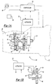
- Figure 1A is a schematic view of a drive system for a vehicle including a transmission;
- Figure 1B is a transmission of the system in Figure 1A in neutral;
- Figure 2A is a graph of a shift synchronization of a high initial engine torque utilizing the present invention; and
- Figure 2B is a graph of a shift synchronization of a low initial engine torque utilizing the present invention.
-
- A drive train for a vehicle is illustrated generally at 20 in Figure 1A. Drivetrain 20 includes an
engine 22 and acontroller 24 which controls the output speed ofengine 22.Controller 24 typically controls the amount of fuel delivered toengine 22 to regulate the output speed and torque.Controller 24 may be a single unit or several functionally specialized units coupled together.Engine 22 has anoutput shaft 23 that passes through aclutch 26 to drive amulti-speed transmission 28. Thetransmission 28 may be of any type known in the art. - The operator may request that the gear shift be effectuated by an electronically controlled
actuator 35 that is coupled tocontroller 24 and actuated byswitch 48, discussed in more detail below. -
Transmission 28 includes a gear 32 which is driven by the output ofengine 22 whenclutch 26 is closed to atransmission input shaft 27. Gear 32 is coupled to aninput shaft 27 which engages and drives a pair of gears 36 each mounted on acountershaft 37. Only one gear 36 andcountershaft 37 are shown. Countershaft 37 rotatesseveral gears 38, only two of which are shown.Gears 38 engage and rotate a plurality ofgears 39 that are mounted to freely rotate on amain output shaft 40. - A
shift yoke 42 slides ashift collar 44 as directed by the vehicle operator to change the speed ratio of thetransmission 28. In the illustrated transmission,collar 44 is internally splined to rotate withshaft 40, but may slide axially alongshaft 40. Collar 44 also hasexternal teeth 45 that are selectively received within an inner peripherally toothed bore 41 on agear 39, best shown in Figure 1B. When theshift collar 44 is in the position shown in Figure 1A, theteeth 45 engage thegear 39 such that thegear 39 rotates thecollar 44, and hence theshaft 40. Thus, in the position shown in Figure 1A, the engine drives the gear 32, which drives gears 36 andcountershafts 37. Thecountershafts 37 drive thegears 38, which drive thegears 39. - Since the
collar 44 is engaged to rotate with onegear 39, then theshaft 40 will be rotated at a speed which is dependent on the gear reduction at the selectedgear 39. When one wishes to shift the transmission to another speed, anothergear 39 is selected and engaged. By varying the gear reductions between theseveral gears 39,transmission 28 is able to selectively achieve several distinct output speed ratios forshaft 40 relative to input fromengine 22. - In moving the
collar 44 to shift to another speed ratio, the initial step is to move theteeth 45 out of engagement from the inner peripherally toothed bore 41 of thegear 39 to the neutral position shown in Figure 1B. When thedrive train 20 is transmitting rotation to theshaft 40 through the arrangement as shown in Figure 1A, however, there is a high torque load on the connection between theteeth 45 and thegear 39 and betweencollar 44 andshaft 40. This high torque load makes it difficult, if not impossible, to slide thecollar 44 relative to thegear 39. For this reason, vehicles have traditionally incorporated aclutch 26. An operator who wishes to shift a transmission to a new speed, initially actuates the clutch. This breaks the torque transmission discussed above, and allows the operator to disengage the transmission and move to neutral. - As discussed above, the prior art allows an operator to shift the transmission to a new speed without operating the clutch. The
collar 44 may be actuated by either the driver manipulating the shift knob or by a powered shifting system such ascontroller 24 andactuator 35. To achieve the ability to shift the gear without clutching aintent switch 48 is provided. Theswitch 48 is utilized to request an upshift or downshift. The first step in achieving a shift is by eliminating the torque lock that prevents sliding movement ofcollar 44 from the position shown in Figure 1A. - The present invention utilizes a method of engaging and disengaging transmission gears in a vehicle. When
intent switch 48 is activated, a torque elimination request is sent tocontroller 24 which processes data to synchronize the engine torque and transmission output torque and shift the transmission gears. The data used bycontroller 24 may be information stored in tables within the controller or elsewhere, information received from devices on the vehicle, or information calculated by the controller. - Data processed by
controller 24 includes an initial torque representing an engine torque and an estimated zero torque representing an estimate of a transmission output shaft torque. The transmission output torque may be estimated in any suitable manner. A rough estimate may be made or a more refined estimate may be made, such as in assignee's copending application no. 09/275,832, filed on March 25, 1999 entitled "Method of Synchronizing Engine Torque With Vehicle Torque Load for Accomplishing Vehicle Transmission Shifting." Alternatively, the zero torque may be determined by taking an actual reading of the transmission output shaft torque. - Instead of dithering the engine torque about the estimated transmission output torque, as in the prior art, the controller sets a high and low band torque offset from the estimated zero torque so that the estimated zero torque is between the high and low band torques. The high and low band torques may be represented as a percentage of the engine's rated torque or in any other suitable manner. Preferably, the estimated transmission output torque is half way between the high and low band torques, as shown in Figure 2A. As an example, the high and low band torque may be set to 20% and 10% of the engine's rated torque, respectively. However, these high and low bands are set based upon the gear in which the transmission is presently engaged. The higher the gear, the narrower the range is between the bands; the lower the gear, the wider the range is between the bands.
-
Controller 24 compares the initial torque to the high band torque and increases the engine torque to the high band torque if the initial torque is less than the high band torque, as shown in Figure 2B. Preferably, the engine torque is increased to the high band torque in a linear fashion. If the initial torque is already above the high band torque, as in Figure 2A, then no initial adjustment is needed. This ensures that the engine torque will be above the estimated transmission output torque, and thus above the actual transmission output torque. - As mentioned above,
actuator 35 includes a piston and cylinder drive that shifts the gear by manipulatingshift collar 44. Theactuator 35 is triggered by at least one shift valve that is electronically energized bycontroller 24. Afterswitch 48 is activated, the controller sends a signal energizing the shift valve when the engine torque is at the greater of the initial torque and high band torque. The engine torque is maintained at the greater of the initial torque and high band torque for a time, W, until the actuator has had sufficient time to fully energize. This ensures that the actuator will be prepared to shift the gear as soon as the engine torque sufficiently approximates the actual transmission output torque. - The engine torque is decayed, or decreased, as a function of a predetermined equation from the higher of the initial torque and high band torque to the low band torque. As the engine torque approaches the low band torque, the engine torque will approach the actual transmission output torque. As soon as the engine torque sufficiently approximates the actual transmission output torque, the actuator will shift the gear. That is, during the decay, the torque will pass through the actual zero torque load, A. At that time, since the piston is preloaded, the piston should drive the gear out of engagement. If for some reason the actuator is unable to shift the gear, a signal will be sent by the controller to an
indicator 49 so that a clutch may be actuated. The indicator may be a light in the vehicle cab. - Engine torque is decayed to the low torque band. Preferably, a second order decay is used to filter engine torque by using the following steps, for example. First the target engine torque, which is the estimated zero torque, is subtracted from a last requested engine torque to yield a first value. The first value is multiplied by a constant representing a percentage of engine torque to yield a second value. The target engine torque is added to the second value to yield a new requested engine torque less than the last requested engine torque thereby decaying the engine torque. The above iteration is repeated until the engine torque has been decayed to the low band torque or the actual transmission output torque. Of course, there are any number of acceptable ways to decrease the engine torque. For example, fueling or any other variable that affects engine torque may be reduced.
Claims (13)
- A method of engaging and disengaging transmission gears in a vehicle comprising the steps of:(a) processing an initial torque representing an engine torque;(b) processing an estimated zero torque representing an estimate of a transmission output shaft torque;(c) setting a high and low band torque wherein the estimated zero torque is between the high and low band torques;(d) comparing the initial torque to the high band torque and increasing the engine torque to the high band torque if the initial torque is less than the high band torque;(e) beginning to urge a gear out of engagement when the engine torque is at the greater of the initial torque and high band torque; and(f) decaying the engine torque from the higher of the initial torque and high band torque to the low band torque to facilitate engaging and disengaging transmission gears.
- The method as set forth in claim 1 wherein step (e) occurs after step (d)
- The method as set forth in claim 1 further including the step of:(g) actuating an intent switch for preparing the transmission to engage or disengage the transmission gears, wherein step (g) occurs prior to step (a).
- The method as set forth in Claim 1 wherein step (e) energizes an actuator to urge the gear out of engagement.
- The method as set forth in claim 4 further including the step of:(h) attempting to actuate the actuator when the engine torque approximates the transmission output shaft torque, wherein step (h) occurs after step (f).
- The method as set forth in Claim 5 further including the step of:(i) activating an indicator if the actuator fails to become actuated so a clutch can be actuated, wherein step (i) occurs after step (h).
- The method as set forth in Claim 6 further including the step of:(j) maintaining the engine torque at the greater of the initial torque and high band torque until the actuator has had sufficient time to fully energize, wherein step (j) occurs after step (e).
- The method as set forth in Claim 7 step (f) further includes the step of:(f1) processing a target engine torque;(f2) subtracting the target engine torque from a last requested engine torque to yield a first value;(f3) multiplying the first value by a constant representing a percentage of engine torque to yield a second value; and(f4) adding the target engine torque to the second value to yield a new requested engine torque less than the last requested engine torque thereby decaying the engine torque.
- A vehicle drive system comprising:an engine having an engine output shaft with an engine torque;a transmission having a transmission input shaft coupled to said engine output shaft and a transmission output shaft selectively coupled to said transmission input shaft by a plurality of gears;an intent switch for preparing to shift said transmission between said plurality of gears;an actuator for shifting between said plurality of gears when said intent switch is actuated; anda controller programmed to process an initial engine torque parameter, a zero torque parameter representing a transmission output shaft torque, and high and low band torque parameters wherein said zero torque parameter is between said high and low band torque parameters, said controller programmed to compare said initial engine torque parameter to said high band torque parameter and send a signal to increase said engine torque to said high band torque parameter if said initial engine torque parameter is less than said high band torque parameter, said controller programmed to energize said actuator when said engine torque is at the greater of said initial engine torque and high band torque parameters, and said controller programmed to decay said engine torque toward said low band torque parameter to facilitate engaging and disengaging transmission gears.
- The vehicle drive system as set forth in Claim 9 wherein said zero torque parameter is an estimate of said transmission output shaft torque.
- The vehicle drive system as set forth in Claim 10 wherein said actuator urges at least one of said plurality of gears out of engagement during said decay such that said gear should move out of engagement when said engine torque approximates said transmission output shaft torque.
- The vehicle drive system as set forth in Claim 11 further including an indicator that becomes activated if said actuator fails to urge at least one of said plurality of gears out of engagement.
- The vehicle drive system as set forth in Claim 12 wherein said controller is programmed to maintain said engine torque at the greater of said initial engine torque and high band torque parameters for a period of time selected to provide said actuator sufficient time to fully energize.
Applications Claiming Priority (3)
| Application Number | Priority Date | Filing Date | Title |
|---|---|---|---|
| US347658 | 1982-02-10 | ||
| US09/347,658 US6126570A (en) | 1999-07-06 | 1999-07-06 | Shift synchronization using decaying torque |
| PCT/US2000/017731 WO2001002209A1 (en) | 1999-07-06 | 2000-06-27 | Shift synchronization using decaying engine torque |
Publications (2)
| Publication Number | Publication Date |
|---|---|
| EP1194310A1 EP1194310A1 (en) | 2002-04-10 |
| EP1194310B1 true EP1194310B1 (en) | 2004-08-25 |
Family
ID=23364673
Family Applications (1)
| Application Number | Title | Priority Date | Filing Date |
|---|---|---|---|
| EP00943229A Expired - Lifetime EP1194310B1 (en) | 1999-07-06 | 2000-06-27 | Shift synchronization using decaying engine torque |
Country Status (6)
| Country | Link |
|---|---|
| US (1) | US6126570A (en) |
| EP (1) | EP1194310B1 (en) |
| AT (1) | ATE274428T1 (en) |
| AU (1) | AU5773000A (en) |
| DE (1) | DE60013292T2 (en) |
| WO (1) | WO2001002209A1 (en) |
Families Citing this family (13)
| Publication number | Priority date | Publication date | Assignee | Title |
|---|---|---|---|---|
| US6352492B1 (en) * | 2000-04-06 | 2002-03-05 | Eaton Corporation | Torque modulation shift control system and method |
| US6520889B1 (en) | 2000-11-01 | 2003-02-18 | Eaton Corporation | Adaptive engine control for shifting to neutral |
| US6406403B1 (en) | 2000-12-21 | 2002-06-18 | Eaton Corporation | Torque ramp down control |
| GB2371839A (en) * | 2001-02-01 | 2002-08-07 | Eaton Corp | Control for selecting automated transmission system shift strategy |
| US6641504B2 (en) | 2001-03-21 | 2003-11-04 | Eaton Corporation | Method and system for establishing an engine speed target for use by a centrifugal clutch control system to launch a vehicle |
| US6539820B2 (en) | 2001-03-21 | 2003-04-01 | Eaton Corporation | Method and system for transmission utilizing centrifugal clutch to overcome transmission tooth-butt |
| SE525105C2 (en) * | 2002-05-13 | 2004-11-30 | Volvo Lastvagnar Ab | Power units for motor vehicles |
| US7480555B2 (en) * | 2004-12-16 | 2009-01-20 | Eaton Corporation | Method for controlling centrifugal clutch engagement using engine torque requests |
| EP2069176A4 (en) * | 2006-09-15 | 2013-01-16 | Volvo Lastvagnar Ab | Method for assuring synchronization between an engine controller and a transmission controller and computer program and product |
| US8448731B2 (en) * | 2007-11-05 | 2013-05-28 | GM Global Technology Operations LLC | Method and apparatus for determination of fast actuating engine torque for a hybrid powertrain system |
| JP5077269B2 (en) * | 2009-03-05 | 2012-11-21 | トヨタ自動車株式会社 | Vehicle shift control device |
| WO2014027065A1 (en) * | 2012-08-16 | 2014-02-20 | Jaguar Land Rover Limited | System and method for selecting a driveline gear ratio |
| EP3514410A1 (en) * | 2018-01-17 | 2019-07-24 | Dana Italia S.r.L. | Electric driveline and method of shifting gears |
Citations (2)
| Publication number | Priority date | Publication date | Assignee | Title |
|---|---|---|---|---|
| EP0316679A1 (en) * | 1987-11-20 | 1989-05-24 | Eaton Corporation | Vehicle drive line shift control system and method |
| US5595551A (en) * | 1994-05-13 | 1997-01-21 | Scania Cv Aktiebolag | Method for control of engine torque during gear changing |
Family Cites Families (11)
| Publication number | Priority date | Publication date | Assignee | Title |
|---|---|---|---|---|
| SE502157C2 (en) * | 1993-12-30 | 1995-09-04 | Saab Scania Ab | Procedure and device for automatic shifting in motor vehicles executed synchronously with the oscillation of the vehicle's driveline |
| JP3350201B2 (en) * | 1994-02-14 | 2002-11-25 | 株式会社日立製作所 | Torque feedback shift control apparatus and method |
| US5582558A (en) * | 1995-07-27 | 1996-12-10 | Rockwell International Corporation | Combined system for assisting shifting of manual transmission |
| US5573477A (en) * | 1995-07-27 | 1996-11-12 | Rockwell International Corporation | Method and apparatus for assisting in shifting transmission to neutral |
| JPH09256883A (en) * | 1996-03-25 | 1997-09-30 | Toyota Motor Corp | Integrated control unit for engine and automatic transmission |
| JPH09291835A (en) * | 1996-04-26 | 1997-11-11 | Honda Motor Co Ltd | Internal combustion engine control device for vehicle |
| JP3594734B2 (en) * | 1996-04-30 | 2004-12-02 | 本田技研工業株式会社 | Control device for internal combustion engine for vehicle |
| EP0805061B1 (en) * | 1996-04-30 | 2002-06-19 | Eaton Corporation | Intent-to-shift semi-automatic shift implementation |
| US6962551B1 (en) * | 1996-06-19 | 2005-11-08 | Eaton Corporation | Automated transmission system control with zero engine flywheel torque determination |
| JP3209104B2 (en) * | 1996-07-30 | 2001-09-17 | トヨタ自動車株式会社 | Control device for vehicle equipped with engine and automatic transmission |
| US5980424A (en) * | 1997-10-21 | 1999-11-09 | Detroit Diesel Corporation | Torque dithering method for controlling a vehicle transmission |
-
1999
- 1999-07-06 US US09/347,658 patent/US6126570A/en not_active Expired - Lifetime
-
2000
- 2000-06-27 WO PCT/US2000/017731 patent/WO2001002209A1/en not_active Ceased
- 2000-06-27 EP EP00943229A patent/EP1194310B1/en not_active Expired - Lifetime
- 2000-06-27 AU AU57730/00A patent/AU5773000A/en not_active Abandoned
- 2000-06-27 DE DE60013292T patent/DE60013292T2/en not_active Expired - Lifetime
- 2000-06-27 AT AT00943229T patent/ATE274428T1/en not_active IP Right Cessation
Patent Citations (2)
| Publication number | Priority date | Publication date | Assignee | Title |
|---|---|---|---|---|
| EP0316679A1 (en) * | 1987-11-20 | 1989-05-24 | Eaton Corporation | Vehicle drive line shift control system and method |
| US5595551A (en) * | 1994-05-13 | 1997-01-21 | Scania Cv Aktiebolag | Method for control of engine torque during gear changing |
Also Published As
| Publication number | Publication date |
|---|---|
| ATE274428T1 (en) | 2004-09-15 |
| AU5773000A (en) | 2001-01-22 |
| DE60013292D1 (en) | 2004-09-30 |
| WO2001002209A1 (en) | 2001-01-11 |
| US6126570A (en) | 2000-10-03 |
| EP1194310A1 (en) | 2002-04-10 |
| DE60013292T2 (en) | 2005-04-28 |
Similar Documents
| Publication | Publication Date | Title |
|---|---|---|
| US5603672A (en) | Method for controlling the output torque of an automatic transmission | |
| US5508916A (en) | Control for engagement of positive clutches in automated mechanical transmission systems | |
| EP0628443B1 (en) | Clutch disengage logic | |
| CA1275720C (en) | Method for controlling amt system including start from stop clutch and fuel control | |
| AU722955B2 (en) | Engine speed retardation on transmission upshift | |
| US6126570A (en) | Shift synchronization using decaying torque | |
| US4850236A (en) | Vehicle drive line shift control system and method | |
| DE102008020956B4 (en) | Vehicle transmission control device | |
| KR100316749B1 (en) | Shift control device and method | |
| US6105449A (en) | Control for controller-assisted, manually shifted, synchronized, input splitter-type compound transmissions | |
| CZ289372B6 (en) | Control system/method for controlling the shifting of automated mechanical transmission system | |
| HU217700B (en) | Method and system for operating automatic gearbox | |
| US6835161B2 (en) | Automated change-speed gearbox and methods for changing gear in such a gearbox | |
| DE69521763T2 (en) | Semi-automatic, mechanical transmission with automatic, forced gear shift | |
| JPS6288850A (en) | Power synchronizer | |
| DE60104461T2 (en) | Control for automatic vehicle transmissions | |
| JPH1073032A (en) | Transmission control method and vehicle semi-automatic shift execution device | |
| CN111615603B (en) | Electric transmission system and gear shifting method | |
| DE19622665A1 (en) | Device and method for commanding a gear after an aborted shift attempt when controlling a manual transmission automatic transmission | |
| WO2004109161A1 (en) | Method for operating the drive train of a motor vehicle | |
| EP0378218B1 (en) | Motor vehicle drive control system | |
| AU757074B2 (en) | Method of synchronizing engine torque with vehicle torque load for accomplishing vehicle transmission shifting | |
| DE60127330T2 (en) | Engine speed control to support the shift synchronization | |
| DE69908692T2 (en) | Adaptive switching force control of an actuator for a splitter transmission | |
| EP1382479B1 (en) | Method for driving off for a vehicle drive system containing a double clutch |
Legal Events
| Date | Code | Title | Description |
|---|---|---|---|
| PUAI | Public reference made under article 153(3) epc to a published international application that has entered the european phase |
Free format text: ORIGINAL CODE: 0009012 |
|
| 17P | Request for examination filed |
Effective date: 20020118 |
|
| AK | Designated contracting states |
Kind code of ref document: A1 Designated state(s): AT BE CH CY DE DK ES FI FR GB GR IE IT LI LU MC NL PT SE |
|
| 17Q | First examination report despatched |
Effective date: 20030414 |
|
| RAP1 | Party data changed (applicant data changed or rights of an application transferred) |
Owner name: ZF FRIEDRICHSHAFEN AKTIENGESELLSCHAFT |
|
| GRAP | Despatch of communication of intention to grant a patent |
Free format text: ORIGINAL CODE: EPIDOSNIGR1 |
|
| GRAS | Grant fee paid |
Free format text: ORIGINAL CODE: EPIDOSNIGR3 |
|
| GRAA | (expected) grant |
Free format text: ORIGINAL CODE: 0009210 |
|
| AK | Designated contracting states |
Kind code of ref document: B1 Designated state(s): AT BE CH CY DE DK ES FI FR GB GR IE IT LI LU MC NL PT SE |
|
| PG25 | Lapsed in a contracting state [announced via postgrant information from national office to epo] |
Ref country code: FR Free format text: LAPSE BECAUSE OF FAILURE TO SUBMIT A TRANSLATION OF THE DESCRIPTION OR TO PAY THE FEE WITHIN THE PRESCRIBED TIME-LIMIT Effective date: 20040825 Ref country code: NL Free format text: LAPSE BECAUSE OF FAILURE TO SUBMIT A TRANSLATION OF THE DESCRIPTION OR TO PAY THE FEE WITHIN THE PRESCRIBED TIME-LIMIT Effective date: 20040825 Ref country code: BE Free format text: LAPSE BECAUSE OF FAILURE TO SUBMIT A TRANSLATION OF THE DESCRIPTION OR TO PAY THE FEE WITHIN THE PRESCRIBED TIME-LIMIT Effective date: 20040825 Ref country code: LI Free format text: LAPSE BECAUSE OF FAILURE TO SUBMIT A TRANSLATION OF THE DESCRIPTION OR TO PAY THE FEE WITHIN THE PRESCRIBED TIME-LIMIT Effective date: 20040825 Ref country code: AT Free format text: LAPSE BECAUSE OF FAILURE TO SUBMIT A TRANSLATION OF THE DESCRIPTION OR TO PAY THE FEE WITHIN THE PRESCRIBED TIME-LIMIT Effective date: 20040825 Ref country code: FI Free format text: LAPSE BECAUSE OF FAILURE TO SUBMIT A TRANSLATION OF THE DESCRIPTION OR TO PAY THE FEE WITHIN THE PRESCRIBED TIME-LIMIT Effective date: 20040825 Ref country code: CH Free format text: LAPSE BECAUSE OF FAILURE TO SUBMIT A TRANSLATION OF THE DESCRIPTION OR TO PAY THE FEE WITHIN THE PRESCRIBED TIME-LIMIT Effective date: 20040825 |
|
| REG | Reference to a national code |
Ref country code: GB Ref legal event code: FG4D |
|
| RIN1 | Information on inventor provided before grant (corrected) |
Inventor name: DEVORE, JAMES, HENRY Inventor name: BOHM, ANDREAS Inventor name: SAYMAN, ROBERT, ANTHONY Inventor name: BOCKMANN, GERHARD Inventor name: HUBER, JON, MICKAEL |
|
| REG | Reference to a national code |
Ref country code: CH Ref legal event code: EP |
|
| REG | Reference to a national code |
Ref country code: IE Ref legal event code: FG4D |
|
| REF | Corresponds to: |
Ref document number: 60013292 Country of ref document: DE Date of ref document: 20040930 Kind code of ref document: P |
|
| REG | Reference to a national code |
Ref country code: SE Ref legal event code: TRGR |
|
| PG25 | Lapsed in a contracting state [announced via postgrant information from national office to epo] |
Ref country code: DK Free format text: LAPSE BECAUSE OF FAILURE TO SUBMIT A TRANSLATION OF THE DESCRIPTION OR TO PAY THE FEE WITHIN THE PRESCRIBED TIME-LIMIT Effective date: 20041125 Ref country code: GR Free format text: LAPSE BECAUSE OF FAILURE TO SUBMIT A TRANSLATION OF THE DESCRIPTION OR TO PAY THE FEE WITHIN THE PRESCRIBED TIME-LIMIT Effective date: 20041125 |
|
| PG25 | Lapsed in a contracting state [announced via postgrant information from national office to epo] |
Ref country code: ES Free format text: LAPSE BECAUSE OF FAILURE TO SUBMIT A TRANSLATION OF THE DESCRIPTION OR TO PAY THE FEE WITHIN THE PRESCRIBED TIME-LIMIT Effective date: 20041206 |
|
| REG | Reference to a national code |
Ref country code: CH Ref legal event code: PL |
|
| NLV1 | Nl: lapsed or annulled due to failure to fulfill the requirements of art. 29p and 29m of the patents act | ||
| PG25 | Lapsed in a contracting state [announced via postgrant information from national office to epo] |
Ref country code: LU Free format text: LAPSE BECAUSE OF NON-PAYMENT OF DUE FEES Effective date: 20050627 Ref country code: IE Free format text: LAPSE BECAUSE OF NON-PAYMENT OF DUE FEES Effective date: 20050627 Ref country code: GB Free format text: LAPSE BECAUSE OF NON-PAYMENT OF DUE FEES Effective date: 20050627 Ref country code: CY Free format text: LAPSE BECAUSE OF FAILURE TO SUBMIT A TRANSLATION OF THE DESCRIPTION OR TO PAY THE FEE WITHIN THE PRESCRIBED TIME-LIMIT Effective date: 20050627 |
|
| PG25 | Lapsed in a contracting state [announced via postgrant information from national office to epo] |
Ref country code: MC Free format text: LAPSE BECAUSE OF NON-PAYMENT OF DUE FEES Effective date: 20050630 |
|
| PLBE | No opposition filed within time limit |
Free format text: ORIGINAL CODE: 0009261 |
|
| STAA | Information on the status of an ep patent application or granted ep patent |
Free format text: STATUS: NO OPPOSITION FILED WITHIN TIME LIMIT |
|
| 26N | No opposition filed |
Effective date: 20050526 |
|
| EN | Fr: translation not filed | ||
| GBPC | Gb: european patent ceased through non-payment of renewal fee |
Effective date: 20050627 |
|
| REG | Reference to a national code |
Ref country code: IE Ref legal event code: MM4A |
|
| PG25 | Lapsed in a contracting state [announced via postgrant information from national office to epo] |
Ref country code: PT Free format text: LAPSE BECAUSE OF NON-PAYMENT OF DUE FEES Effective date: 20050125 |
|
| PGFP | Annual fee paid to national office [announced via postgrant information from national office to epo] |
Ref country code: IT Payment date: 20090619 Year of fee payment: 10 |
|
| PG25 | Lapsed in a contracting state [announced via postgrant information from national office to epo] |
Ref country code: IT Free format text: LAPSE BECAUSE OF NON-PAYMENT OF DUE FEES Effective date: 20100627 |
|
| PGFP | Annual fee paid to national office [announced via postgrant information from national office to epo] |
Ref country code: SE Payment date: 20130612 Year of fee payment: 14 Ref country code: DE Payment date: 20130619 Year of fee payment: 14 |
|
| REG | Reference to a national code |
Ref country code: DE Ref legal event code: R119 Ref document number: 60013292 Country of ref document: DE |
|
| PG25 | Lapsed in a contracting state [announced via postgrant information from national office to epo] |
Ref country code: SE Free format text: LAPSE BECAUSE OF NON-PAYMENT OF DUE FEES Effective date: 20140628 |
|
| REG | Reference to a national code |
Ref country code: SE Ref legal event code: EUG |
|
| REG | Reference to a national code |
Ref country code: DE Ref legal event code: R079 Ref document number: 60013292 Country of ref document: DE Free format text: PREVIOUS MAIN CLASS: B60K0041080000 Ipc: B60W0010040000 |
|
| REG | Reference to a national code |
Ref country code: DE Ref legal event code: R119 Ref document number: 60013292 Country of ref document: DE Effective date: 20150101 Ref country code: DE Ref legal event code: R079 Ref document number: 60013292 Country of ref document: DE Free format text: PREVIOUS MAIN CLASS: B60K0041080000 Ipc: B60W0010040000 Effective date: 20150312 |
|
| PG25 | Lapsed in a contracting state [announced via postgrant information from national office to epo] |
Ref country code: DE Free format text: LAPSE BECAUSE OF NON-PAYMENT OF DUE FEES Effective date: 20150101 |