EP1194027A2 - Electrical connection box for a vehicule - Google Patents
Electrical connection box for a vehicule Download PDFInfo
- Publication number
- EP1194027A2 EP1194027A2 EP01308137A EP01308137A EP1194027A2 EP 1194027 A2 EP1194027 A2 EP 1194027A2 EP 01308137 A EP01308137 A EP 01308137A EP 01308137 A EP01308137 A EP 01308137A EP 1194027 A2 EP1194027 A2 EP 1194027A2
- Authority
- EP
- European Patent Office
- Prior art keywords
- voltage
- relay
- electrical connection
- connection box
- casing
- Prior art date
- Legal status (The legal status is an assumption and is not a legal conclusion. Google has not performed a legal analysis and makes no representation as to the accuracy of the status listed.)
- Granted
Links
Images


Classifications
-
- H—ELECTRICITY
- H05—ELECTRIC TECHNIQUES NOT OTHERWISE PROVIDED FOR
- H05K—PRINTED CIRCUITS; CASINGS OR CONSTRUCTIONAL DETAILS OF ELECTRIC APPARATUS; MANUFACTURE OF ASSEMBLAGES OF ELECTRICAL COMPONENTS
- H05K7/00—Constructional details common to different types of electric apparatus
- H05K7/02—Arrangements of circuit components or wiring on supporting structure
- H05K7/026—Multiple connections subassemblies
-
- H—ELECTRICITY
- H05—ELECTRIC TECHNIQUES NOT OTHERWISE PROVIDED FOR
- H05K—PRINTED CIRCUITS; CASINGS OR CONSTRUCTIONAL DETAILS OF ELECTRIC APPARATUS; MANUFACTURE OF ASSEMBLAGES OF ELECTRICAL COMPONENTS
- H05K5/00—Casings, cabinets or drawers for electric apparatus
- H05K5/06—Hermetically-sealed casings
- H05K5/069—Other details of the casing, e.g. wall structure, passage for a connector, a cable, a shaft
Definitions
- the present invention relates to an electrical connection box which is suitable to be mounted on a vehicle, particularly one to which a high voltage is to be applied, and to a vehicle having such a box installed.
- Normally one secondary, i.e. rechargeable, battery having a rated voltage of 12V and a maximum nominal voltage of 14V is mounted on an automobile of the internal combustion engine type.
- a voltage up to the maximum voltage of 14V is applied from the battery to a circuit composed of bus bars and the like accommodated in an electrical connection box.
- the power supply is distributed by the internal circuit of the electrical connection box.
- the operation of electric/electronic component parts mounted on the vehicle is controlled through electric wires connected with the internal circuit.
- a rated voltage of 24V and a maximum voltage of 28V are applied to a circuit, by a battery structure.
- the diameter of the electric wires used has become larger. Further, with rapid increase of the number of electric/electronic component parts, the number of electric wires has increased recently, which has increased the diameter of a wire harness comprising a bundle of electric wires. Consequently, the weight of the electric wires to be wired on a vehicle body has increased.
- the suction and exhaust devices of the engine As described above, if the power supply from the battery is incapable of operating the suction and exhaust devices of the engine, they are mechanically operated. In this case, it is impossible to accomplish fine control of the operation of the suction and exhaust devices. Further much fuel is consumed, which pollutes the environment. Accordingly, it is preferable to operate the suction and exhaust devices of the engine and the like not mechanically but electrically by the power supply from the battery.
- a high voltage of about 42V it is preferable to apply a high voltage of about 42V to the electromotive power steering motor, the suction and exhaust devices of the engine, the fan, other devices requiring a high voltage.
- the rated voltage of 12V maximum voltage: 14V
- Water is liable to penetrate into terminal recesses of a relay accommodation structure at the exterior of an electrical connection box mounted in a vehicle from a wall partitioning the recesses from each other.
- a leak current is liable to be generated between terminals of the relay to which the high voltage of, for example, about 42V is applied. This is because water penetrates into a (+) terminal insertion portion of the relay accommodation part and a (-) terminal insertion portion thereof from a partitioning wall partitioning them from each other. From there, water may also penetrate into the box to cause leak currents between bus bars.
- an electrical connection box having
- the groove may be formed on the upper edge or end surface of the partition wall so as to slope in one direction only along the wall between the terminal insertion portions, or may have a higher central portion and extend linearly downward in two directions to the exterior of the relay accommodation part. That is, it is preferable to configure the groove in such a way that water which lodges on the partitioning wall flows linearly downward through the groove to the exterior of the relay accommodation part.
- the high voltage to be applied to the high-voltage bus bar is at least 28V, particularly 42V.
- the reason why the high voltage to be applied to the high-voltage bus bar is set to 42V is partly because using a voltage close to or above 50V for the high-voltage bus bar may be more dangerous.
- the present inventors have conducted salt water experiments in order to ascertain the degree of risk when applying a voltage of 42V in an electrical junction box suitable for use in an automobile engine compartment, as follows:-
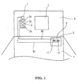
- an engine E mounted in an engine compartment X provides drive of the vehicle and generates electrical power, e.g. through a conventional alternator (not shown).
- a low-voltage battery structure 1 and a high-voltage battery structure 2 are mounted in the engine compartment X, and are charged by the alternator.
- the low-voltage battery structure 1 consists of a conventional general-purpose rechargeable battery having a rated voltage 12V and a nominal maximum voltage of 14V.
- the high-voltage battery 2 consists of three battery units 2a, 2b and 2c connected in series to generate a nominal maximum voltage of 42V.
- Each of the three battery units, 2a, 2b and 2c have a rated voltage of 12V (nominal maximum 14V).
- 12V rechargeable (secondary) battery units are conventional. Needless to say, it is possible to use a single battery having a maximum voltage of 42V.
- the batteries 1, 2 themselves and their connections to the alternator are conventional and need not be described in detail here.
- the low-voltage battery structure 1 is connected to low-voltage bus bars 10 accommodated in an electrical connection box 3 in the form of a junction box mounted in the vehicle interior Y (or, depending on the vehicle, in the engine room) to apply a low voltage (maximum voltage: 14V) to the low-voltage bus bars 10.
- an electrical connection box 3 in the form of a junction box mounted in the vehicle interior Y (or, depending on the vehicle, in the engine room) to apply a low voltage (maximum voltage: 14V) to the low-voltage bus bars 10.
- the high-voltage battery structure 2 is connected to high-voltage bus bars 11 accommodated in the same electrical connection box 3 to apply a high voltage (maximum voltage: 42V) to the high-voltage bus bars 11.
- the load side of the high-voltage bus bars 11 is connected to electrical devices or actuators to operate them electromotively.
- the actuators include a power steering motor, suction and exhaust devices of the engine, and like devices consuming high power.
- the load side of the low-voltage bus bars 10 is connected to appliances (not shown) such as sensors, lamps, and like devices consuming relatively low power, such as are typically provided in an automobile.
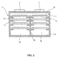
- the electrical connection box 3 has a casing providing two compartments 4a and 4b separated by a partition wall 3b standing up from a bottom wall 3a.
- the compartment 4a accommodates insulation plates 12 carrying the low-voltage bus bars 10 one above another, while the compartment 4b accommodates the insulation plates 13 carrying the high-voltage bus bars 11 also one above another.
- a relay accommodation structure 5 at which in use the low-voltage bus bars 10 and electrical relays are connected to each other and a relay accommodation structure 6 at which in use the high-voltage bus bars 11 and electrical relays are connected to each other.
- the relay accommodation structures 5 and 6 tabs formed by bending the bus bars 10 and 11 are connected to terminals of the relays directly or through relay terminals.
- the relays which are not shown are typically of a conventional type and have terminals to be inserted at the relay accommodation structures.
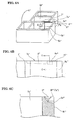
- the relay accommodation structure 6 for the high-voltage bus bar 11 has upstanding walls, integral with the casing wall 5a, defining a (+) terminal insertion recess 6a, a vacant terminal insertion recess 6b, and a (-) terminal insertion recess 6c arranged in a row in parallel with one another, with partition walls partitioning them from one another; and a (+) terminal insertion recess 6d and a (-) terminal insertion recess 6e arranged in a row in parallel with one another, with a partition wall partitioning them from each other.
- the terminal insertion recesses 6a, 6b, 6c, 6d, 6e are arranged in the shape of a letter T.
- the (+) terminal insertion recess 6d is adjacent to all of the (+) terminal insertion recess 6a, the vacant terminal insertion recess 6b, and the (-) terminal insertion recess 6c through a partition wall 7.
- the upstanding walls defining the insertion portions are formed in one-piece with the upper walls 3c of the box, by plastics moulding.
- an approximately semicircular section groove 8 (also seen in Fig. 3) is formed on the upper end surface of a (+-) boundary portion 7a of the partition wall 7 partitioning the (+) terminal insertion recess 6d and the (-) terminal insertion recess 6c from each other by forming the central portion of the (+-) boundary portion 7a lower than both edges thereof over the whole length thereof.
- the groove 8 extends linearly downward to an outer surface 6i of a side wall 6g of the (-) terminal insertion recess 6c perpendicular to a side wall 6f thereof through the upper end surface of the side wall 6f continuous with the (+-) boundary portion 7a.
- the groove 8 penetrates through the upper end surface of the side wall 6g to the outer surface 6i to form an opening 8a.
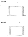
- a groove 8' is also formed on the partition wall 7 disposed between the (+) terminal insertion recess 6d and the (-) terminal insertion recess 6e. Both ends of the groove 8' inclines downward toward the outside.
- the groove 8' may be so shaped that it inclines entirely from its centre as shown in Fig. 5A or it inclines at only both ends as shown in Fig. 5B.
- Figs. 6A, 6B and 6C show a further embodiment, in which a groove 8" V-shaped in section is formed on the upper end surface of a (+-) boundary portion 7a' of a partition wall 7' of a relay accommodation structure 6'.
- a groove 8" V-shaped in section is formed on the upper end surface of a (+-) boundary portion 7a' of a partition wall 7' of a relay accommodation structure 6'.
- the bottom surface of the groove 8" inclines downward toward an outer surface 6h' of the side wall 6f' to form an opening 8a" on the outer surface 6h'.
- the groove 8" inclines downward toward the opening 8a" over its whole length.
- the circuits 5 of these embodiments are thus applied to an automobile on which the battery of the rated voltage of 12V is mounted. But in the case where a maximum voltage of 28V is applied to a bus bar in the automobile or a larger vehicle such as a truck, the bus bar to which the voltage of 28V is applied is the low-voltage bus bar and the bus bar to which the voltage of 42V is applied is the high-voltage bus bar.
- the construction of the circuit 5 and connection box in this case is the same as that of the embodiments.
- the maximum voltage of 42V is applied to the high-voltage bus bar 11.
- a high voltage of 42V - 200V can be applied to the high-voltage bus bars 11, provided that safety is ensured.
- the sectional configuration of the drain groove is semicircular or V-shaped, but may be rectangular, with its bottom surface having a plane configuration.
- a groove is formed on the upper edge of the partition wall partitioning the (+) terminal insertion recess of the relay accommodation structure for connecting the high-voltage bus bar and the relay to each other from the (-) terminal insertion recess thereof in such a way that the groove inclines downward the outside of the relay accommodation structure. Therefore, water collecting on the upper edge of the partition wall can flow downward along the groove to the outside of the relay accommodation structure.
Landscapes
- Engineering & Computer Science (AREA)
- Microelectronics & Electronic Packaging (AREA)
- Connection Or Junction Boxes (AREA)
- Connector Housings Or Holding Contact Members (AREA)
Abstract
Description
Claims (4)
- An electrical connection box having a casing (3) and at least one bus bar (11) mounted within said casing to which in use a nominal maximum voltage of not less than 14V and not more than 200V is applied, wherein on an upper wall (3c) of said casing there is a relay accommodation structure (6) to receive at least one electrical relay in use and comprising upstanding walls defining at least first and second recesses (6a, 6b; 6d, 6e; 6c', 6d') at which positive and negative terminals of the relay are respectively inserted, said first and second recesses being partitioned from each other by one of said upstanding walls which has an upper edge at which an inclined groove (8, 8', 8") is provided for carrying away water by gravity.
- An electrical connection box according to claim 1, wherein said nominal maximum voltage is 42V.
- A vehicle having an electrical power source (2) providing a nominal maximum voltage of not less than 14V and not more than 200V, an electrical connection box according to claim 1 or 2, and an electrical relay mounted at said relay accommodation structure of said box, said electrical power source being electrically connected to said bus bar (11) of said box.
- A vehicle according to claim 3, wherein said nominal maximum voltage is 42V.
Applications Claiming Priority (2)
| Application Number | Priority Date | Filing Date | Title |
|---|---|---|---|
| JP2000294565 | 2000-09-27 | ||
| JP2000294565A JP2002112435A (en) | 2000-09-27 | 2000-09-27 | Electrical junction box for high voltage |
Publications (3)
| Publication Number | Publication Date |
|---|---|
| EP1194027A2 true EP1194027A2 (en) | 2002-04-03 |
| EP1194027A3 EP1194027A3 (en) | 2004-05-19 |
| EP1194027B1 EP1194027B1 (en) | 2007-10-31 |
Family
ID=18777150
Family Applications (1)
| Application Number | Title | Priority Date | Filing Date |
|---|---|---|---|
| EP01308137A Expired - Lifetime EP1194027B1 (en) | 2000-09-27 | 2001-09-25 | Electrical connection box for a vehicule |
Country Status (4)
| Country | Link |
|---|---|
| US (1) | US6443748B1 (en) |
| EP (1) | EP1194027B1 (en) |
| JP (1) | JP2002112435A (en) |
| DE (1) | DE60131128T2 (en) |
Families Citing this family (15)
| Publication number | Priority date | Publication date | Assignee | Title |
|---|---|---|---|---|
| US6650087B2 (en) * | 2000-07-04 | 2003-11-18 | Sumitomo Wiring Systems, Ltd. | Vehicle having an electrical connection box and electrical connection box for use in the vehicle |
| JP2002027636A (en) * | 2000-07-04 | 2002-01-25 | Sumitomo Wiring Syst Ltd | Circuits used in high-voltage electrical junction boxes |
| JP4047656B2 (en) * | 2002-08-08 | 2008-02-13 | 矢崎総業株式会社 | Split-type electrical junction box |
| US7077667B2 (en) * | 2003-04-22 | 2006-07-18 | Yazaki Corporation | Electrical junction box |
| JP4265990B2 (en) * | 2004-04-12 | 2009-05-20 | 株式会社オートネットワーク技術研究所 | Electrical junction box |
| JP4374296B2 (en) * | 2004-08-05 | 2009-12-02 | 株式会社オートネットワーク技術研究所 | Electrical junction box |
| CA2563415C (en) * | 2005-04-11 | 2014-02-04 | Autonetworks Technologies, Ltd. | Electric power distribution system |
| JP5582093B2 (en) * | 2011-05-17 | 2014-09-03 | 住友電装株式会社 | Vehicle side connector |
| JP5851221B2 (en) * | 2011-12-02 | 2016-02-03 | 東洋電装株式会社 | Handle switch |
| JP5794938B2 (en) * | 2012-03-14 | 2015-10-14 | 古河電気工業株式会社 | High voltage electrical junction box |
| JP2015225771A (en) * | 2014-05-28 | 2015-12-14 | 住友電装株式会社 | Inlet for compound type charging |
| US10217693B1 (en) * | 2017-08-29 | 2019-02-26 | Nio Usa, Inc. | Methods and systems for high voltage component cooling in electric vehicle for fast charge |
| US10608301B2 (en) | 2017-08-29 | 2020-03-31 | Nio Usa, Inc. | Power electronics with integrated busbar cooling |
| JP7240265B2 (en) * | 2019-06-12 | 2023-03-15 | 株式会社Subaru | Vehicle high voltage junction box |
| CN110536572B (en) * | 2019-10-10 | 2024-09-24 | 北京普莱德新能源电池科技有限公司 | An electrical box |
Family Cites Families (16)
| Publication number | Priority date | Publication date | Assignee | Title |
|---|---|---|---|---|
| JP2695068B2 (en) * | 1991-06-20 | 1997-12-24 | 住友電気工業株式会社 | Anti-lock brake system |
| DE9211314U1 (en) * | 1992-08-22 | 1992-10-29 | RIA electronic Albert Metz, 7712 Blumberg | Multi-pole terminal block |
| US5785532A (en) * | 1993-06-09 | 1998-07-28 | United Technologies Automotive, Inc. | Power distribution box and system |
| US5458496A (en) * | 1993-07-12 | 1995-10-17 | Sumitomo Wiring Systems, Ltd. | Charge coupling for electric vehicle |
| US5451170A (en) * | 1993-09-28 | 1995-09-19 | Reliance Comm/Tec Corporation | Terminal block with protection |
| JP2891324B2 (en) * | 1994-05-25 | 1999-05-17 | 矢崎総業株式会社 | Waterproof seal structure of electrical junction box |
| US6099348A (en) * | 1994-12-05 | 2000-08-08 | Horton; Robert F. | Circuit connector block |
| JP3684648B2 (en) * | 1995-11-22 | 2005-08-17 | 松下電工株式会社 | Waterproof case |
| JP3527000B2 (en) * | 1996-01-26 | 2004-05-17 | 本田技研工業株式会社 | Switch box with connector |
| JP3318185B2 (en) * | 1996-03-14 | 2002-08-26 | 矢崎総業株式会社 | Assembly structure of electrical module |
| US6074240A (en) * | 1996-10-16 | 2000-06-13 | Marconi Communications Inc. | Terminal block |
| JPH10243523A (en) * | 1997-02-24 | 1998-09-11 | Yazaki Corp | Drainage structure of electrical junction box |
| JPH11165565A (en) * | 1997-12-03 | 1999-06-22 | Toyoda Gosei Co Ltd | Vehicle interior structure and method of assembling the same |
| US6238225B1 (en) * | 1998-09-23 | 2001-05-29 | Tvm Group, Inc. | Bus bar assembly |
| JP2000251977A (en) * | 1999-02-26 | 2000-09-14 | Fujitsu Ltd | Power supply terminal |
| JP3463632B2 (en) * | 1999-12-02 | 2003-11-05 | 住友電装株式会社 | Electrical junction box |
-
2000
- 2000-09-27 JP JP2000294565A patent/JP2002112435A/en not_active Abandoned
-
2001
- 2001-09-25 DE DE60131128T patent/DE60131128T2/en not_active Expired - Fee Related
- 2001-09-25 EP EP01308137A patent/EP1194027B1/en not_active Expired - Lifetime
- 2001-09-26 US US09/962,215 patent/US6443748B1/en not_active Expired - Fee Related
Also Published As
| Publication number | Publication date |
|---|---|
| US20020037659A1 (en) | 2002-03-28 |
| EP1194027A3 (en) | 2004-05-19 |
| EP1194027B1 (en) | 2007-10-31 |
| US6443748B1 (en) | 2002-09-03 |
| JP2002112435A (en) | 2002-04-12 |
| DE60131128D1 (en) | 2007-12-13 |
| DE60131128T2 (en) | 2008-08-14 |
Similar Documents
| Publication | Publication Date | Title |
|---|---|---|
| EP1194027B1 (en) | Electrical connection box for a vehicule | |
| US6506061B2 (en) | Electrical connection box to be mounted on a vehicle | |
| US6478585B2 (en) | Electrical connection box for a vehicle | |
| EP1174950B1 (en) | Electrical connection box and vehicle including it | |
| US6629850B2 (en) | Electrical connection box for a vehicle | |
| CN103444032A (en) | High voltage electrical junction box | |
| DE102017123718A1 (en) | accumulator | |
| JP2002343331A (en) | Battery | |
| US6542064B2 (en) | Fuse | |
| WO2014017571A1 (en) | Electrical connection box | |
| US6650087B2 (en) | Vehicle having an electrical connection box and electrical connection box for use in the vehicle | |
| DE102018118083B4 (en) | BATTERY PACK | |
| US7508164B2 (en) | Battery pack having control devices of differing heights | |
| US6780066B2 (en) | Arc discharge preventing device | |
| JP2004119187A (en) | Battery configuration method | |
| EP1172901B1 (en) | Vehicle having an electrical connection box and electrical connection box for use in the vehicle | |
| US11955788B2 (en) | Electrical connection box | |
| JP2002034121A (en) | Circuits used in high-voltage electrical junction boxes | |
| JP2002034122A (en) | Electrical junction box for high voltage | |
| JP2002084630A (en) | Electrical junction box for high voltage | |
| KR20250059225A (en) | Electronic device | |
| JP2002027639A (en) | Electrical junction box for high voltage | |
| JP2000150014A (en) | Short-circuit prevention structure for box with circuit |
Legal Events
| Date | Code | Title | Description |
|---|---|---|---|
| PUAI | Public reference made under article 153(3) epc to a published international application that has entered the european phase |
Free format text: ORIGINAL CODE: 0009012 |
|
| 17P | Request for examination filed |
Effective date: 20011015 |
|
| AK | Designated contracting states |
Kind code of ref document: A2 Designated state(s): AT BE CH CY DE DK ES FI FR GB GR IE IT LI LU MC NL PT SE TR |
|
| AX | Request for extension of the european patent |
Free format text: AL;LT;LV;MK;RO;SI |
|
| PUAL | Search report despatched |
Free format text: ORIGINAL CODE: 0009013 |
|
| AK | Designated contracting states |
Kind code of ref document: A3 Designated state(s): AT BE CH CY DE DK ES FI FR GB GR IE IT LI LU MC NL PT SE TR |
|
| AX | Request for extension of the european patent |
Extension state: AL LT LV MK RO SI |
|
| RIC1 | Information provided on ipc code assigned before grant |
Ipc: 7H 02G 3/08 B Ipc: 7H 05K 5/02 A |
|
| AKX | Designation fees paid |
Designated state(s): DE FR GB |
|
| GRAP | Despatch of communication of intention to grant a patent |
Free format text: ORIGINAL CODE: EPIDOSNIGR1 |
|
| GRAS | Grant fee paid |
Free format text: ORIGINAL CODE: EPIDOSNIGR3 |
|
| GRAA | (expected) grant |
Free format text: ORIGINAL CODE: 0009210 |
|
| AK | Designated contracting states |
Kind code of ref document: B1 Designated state(s): DE FR GB |
|
| REG | Reference to a national code |
Ref country code: GB Ref legal event code: FG4D |
|
| REF | Corresponds to: |
Ref document number: 60131128 Country of ref document: DE Date of ref document: 20071213 Kind code of ref document: P |
|
| EN | Fr: translation not filed | ||
| PLBE | No opposition filed within time limit |
Free format text: ORIGINAL CODE: 0009261 |
|
| STAA | Information on the status of an ep patent application or granted ep patent |
Free format text: STATUS: NO OPPOSITION FILED WITHIN TIME LIMIT |
|
| 26N | No opposition filed |
Effective date: 20080801 |
|
| PG25 | Lapsed in a contracting state [announced via postgrant information from national office to epo] |
Ref country code: FR Free format text: LAPSE BECAUSE OF FAILURE TO SUBMIT A TRANSLATION OF THE DESCRIPTION OR TO PAY THE FEE WITHIN THE PRESCRIBED TIME-LIMIT Effective date: 20080704 |
|
| PGFP | Annual fee paid to national office [announced via postgrant information from national office to epo] |
Ref country code: DE Payment date: 20081002 Year of fee payment: 8 |
|
| GBPC | Gb: european patent ceased through non-payment of renewal fee |
Effective date: 20080925 |
|
| PG25 | Lapsed in a contracting state [announced via postgrant information from national office to epo] |
Ref country code: GB Free format text: LAPSE BECAUSE OF NON-PAYMENT OF DUE FEES Effective date: 20080925 |
|
| PG25 | Lapsed in a contracting state [announced via postgrant information from national office to epo] |
Ref country code: DE Free format text: LAPSE BECAUSE OF NON-PAYMENT OF DUE FEES Effective date: 20100401 |