EP1193827A2 - Rotor structure for permanent-magnet motor - Google Patents
Rotor structure for permanent-magnet motor Download PDFInfo
- Publication number
- EP1193827A2 EP1193827A2 EP01122884A EP01122884A EP1193827A2 EP 1193827 A2 EP1193827 A2 EP 1193827A2 EP 01122884 A EP01122884 A EP 01122884A EP 01122884 A EP01122884 A EP 01122884A EP 1193827 A2 EP1193827 A2 EP 1193827A2
- Authority
- EP
- European Patent Office
- Prior art keywords
- annular
- laminated stack
- end plates
- rotor structure
- annular end
- Prior art date
- Legal status (The legal status is an assumption and is not a legal conclusion. Google has not performed a legal analysis and makes no representation as to the accuracy of the status listed.)
- Granted
Links
Images


Classifications
-
- H—ELECTRICITY
- H02—GENERATION; CONVERSION OR DISTRIBUTION OF ELECTRIC POWER
- H02K—DYNAMO-ELECTRIC MACHINES
- H02K1/00—Details of the magnetic circuit
- H02K1/06—Details of the magnetic circuit characterised by the shape, form or construction
- H02K1/22—Rotating parts of the magnetic circuit
- H02K1/28—Means for mounting or fastening rotating magnetic parts on to, or to, the rotor structures
- H02K1/30—Means for mounting or fastening rotating magnetic parts on to, or to, the rotor structures using intermediate parts, e.g. spiders
-
- H—ELECTRICITY
- H02—GENERATION; CONVERSION OR DISTRIBUTION OF ELECTRIC POWER
- H02K—DYNAMO-ELECTRIC MACHINES
- H02K1/00—Details of the magnetic circuit
- H02K1/06—Details of the magnetic circuit characterised by the shape, form or construction
- H02K1/22—Rotating parts of the magnetic circuit
- H02K1/27—Rotor cores with permanent magnets
- H02K1/2706—Inner rotors
- H02K1/272—Inner rotors the magnetisation axis of the magnets being perpendicular to the rotor axis
- H02K1/274—Inner rotors the magnetisation axis of the magnets being perpendicular to the rotor axis the rotor consisting of two or more circumferentially positioned magnets
- H02K1/2753—Inner rotors the magnetisation axis of the magnets being perpendicular to the rotor axis the rotor consisting of two or more circumferentially positioned magnets the rotor consisting of magnets or groups of magnets arranged with alternating polarity
- H02K1/276—Magnets embedded in the magnetic core, e.g. interior permanent magnets [IPM]
-
- H—ELECTRICITY
- H02—GENERATION; CONVERSION OR DISTRIBUTION OF ELECTRIC POWER
- H02K—DYNAMO-ELECTRIC MACHINES
- H02K2201/00—Specific aspects not provided for in the other groups of this subclass relating to the magnetic circuits
- H02K2201/09—Magnetic cores comprising laminations characterised by being fastened by caulking
Definitions
- This invention relates to rotor structures for three-phase synchronous permanent-magnet motor specifically used as motors or electric power generators and, more particularly, to a rotor structure, for a permanent-magnet motor, which has an increased strength to restrict deformation of the rotor structure caused at a high speed and which is specifically suited for an electric motor or an electric power generator of an electric vehicle.
- a current permanent-magnet motor has achieved an extremely high operating performance to be suited for use in an automotive vehicle and has been already put to practical use. Also, it has been a usual practice to employ the permanent-magnet motor as an auxiliary propelling motor in a hybrid type electric vehicle. Thus, it is known that the permanent-magnet motor has an excellent operating characteristic among other electric motors. However, the permanent-magnet motor has many other remaining technical matters to be solved, and a still further development over the existing permanent-magnet motor is expected to solve the above technical matters to provide a further improved operating performance.
- Typical examples of the above-mentioned technical matters involve a miniaturization of the motor for a reduced space, and a property of high speed rotation of the motor to realize one of various expedients to provide a high output performance.
- the motor rotates at an extremely high speed of more than 10,000 rpm, it is required for the rotor structure to have an extremely high strength.
- FIG. 1 shows a typical example of a rotor structure for a permanent-magnet motor of a related art.
- the rotor structure is constructed having a pair of axially spaced annular end plates 1, 1, and an annular laminated stack 2 of electromagnetic sheets.
- the annular laminated stack 2 and the annular end plates 1, 1 are fixedly supported with a cylindrical core buck 3 of the cylindrical core buck 3, which is connected to a rotor shaft 5 via a connecting portion 6 for rotating movement therewith.
- the annular laminated stack 2 has plural permanent magnets 4, 4 located at circumferentially, equally spaced positions. While, in FIG. 2, only a single pole for the permanent magnets 4, 4 is shown, it is to be noted that the motor shown in FIGS.
- the motor also has a magnet retaining structure wherein the magnet for one pole is divided into two pieces, with a central portion of one pole forming a bridge configuration to provide the magnet retaining structure having an increased strength to resist the centrifugal force.
- the rotor structure should be improved to provide a further increased durability and strength in order to meet the need for the high output performance and the property of high speed rotation required in recent years. Also, it is required for the rotor structure to be manufactured in a simplified process to provide a structure having a high reliability without the use of an electronic beam welding technique that requires a high skill.
- the present invention has been made to address the above technical matters and has an object to provide a rotor structure, for a permanent-magnet motor, which ensures an increased strength and durability even at high speed rotation and which has a structure enabled to be manufactured without the use of a highly skilled fabricating technique such as an electronic beam welding technique.
- a rotor structure for a permanent-magnet motor which comprises an annular laminated stack of electromagnetic steel sheets incorporating therein a permanent magnets, a pair of annular end plates between which the annular laminated stack is sandwiched, a cylindrical core buck having its outer circumferential periphery carrying thereon the annular laminated stack and the annular end plates, and a rotor shaft integrally connected to the cylindrical core buck to be rotatable therewith.
- Each outer end surface of the annular laminated stack has a plurality of first contoured fixing portions, and an inner surface of each of the annular end plates has a plurality of second contoured fixing portions.
- the annular laminated stack and the annular end plates are fixedly coupled to one another by caulking at the first and second fixing portions.
- a rotor structure for a permanent-magnet motor which comprises an annular laminated stack of electromagnetic steel sheets incorporating therein permanent magnets, annular means holding the annular laminated stack at both sides thereof in a fixed place, cylindrical means carrying thereon the annular laminated stack and the annular means, and a rotor shaft integrally connected to the cylindrical means to be rotatable therewith.
- Each outer end surface of the annular laminated stack has a plurality of first contoured fixing portions
- the annular means has a plurality of second contoured fixing portions.
- the annular laminated stack and the annular means are fixedly coupled to one another by caulking at the first and second fixing portions.
- a first preferred embodiment of a rotor structure for an electric rotary machine according to the present invention will be explained below with reference to FIG. 3.
- FIG. 3 is a cross sectional view illustrating an essential part of the rotor structure R.
- the rotor structure R includes a rotor shaft 5, a connecting section 6 extending radially outward from an outer circumferential periphery of the rotor shaft 5, a cylindrical core buck 3 integrally connected to the connecting portion 6, an annular laminated stack 2 of electromagnetic steel sheets, and first and second annular end plates 1a, 1b fixed to right and left end faces of the annular laminated stack 2 by caulking.
- the annular laminated stack 2 has a plurality of circumferentially equally spaced caulked portions 8.
- the annular laminated stack has the right end face formed with a plurality of axially concave recesses 8a and the left end face formed with a plurality of axially convex projections 8b, with the concave recesses 8a and the convex projections 8b serving as a first fixing means.
- the plural axial projections 7a of the annular end plate 1a and the axial recesses 7b of the annular end plate 1b form a second fixing means.
- a right distal end of the cylindrical core buck 3 is formed with an annular flange 3a which radially extends outward from the outer circumferential periphery of the cylindrical core buck 3 and which functions to hold the annular end plate 1a in a fixed plate.
- a left distal end portion of the cylindrical core buck 3 has a C-shaped ring 9 to hold the other annular end plate 1b in a fixed place.
- the right annular end plate 1a has an axially inwardly extending annular projection 7a which is fitted to the corresponding annular recess 8a of the annular laminated stack 2, and the left end plate 1b has an axially inwardly extending annular recess 7b which is fitted to the annular projection of the core stack 2.
- each of the annular end plates 1a,1b is made of non-magnetic material. If the annular end plates 1a,1b are made of magnetic material, the magnetic flux created in the core stack 2 by the plural permanent magnets supported in the annular laminated stack 2 is dissipated to the annular end plates 1a, 1b, with a resultant loss caused in an output power of an electromagnetic rotary machine. It is desired for the rotor structure R that the magnetic flux is oriented only toward a stator (not shown), which is located in the vicinity of an outer circumferential periphery of the annular laminated stack 2, to minimize the loss in the output power of the electromagnetic rotary machine.
- each of the annular end plates are preferably made of stainless steel, brass, copper or aluminum, etc.
- the annular end plates it is preferable for the annular end plates to be made of stainless steel represented by SUS 304 in a JIS clarification such as a stainless steel bar defined under JISG4303, a stainless steel plate or stainless steel belt formed by hot rolling under JISG4304 and a stainless steel plate or stainless steel belt formed under JISG4305.
- the SUS 304 material is widely used in various applications and is easy to be available in the market and provides a sufficient strength preferably suited for the material of the end plates.
- each of the annular end plates 1a, 1b is designed to have a thickness of 4 mm to ensure a sufficient bending rigidity.
- the momentum forces are received with the core stack 2, and the annular radial protrusion 3a of the core cylindrical core buck 3 and the C-ring 9.
- the C-ring 9 is widely in use as a retaining piece which is readily available in the market and which is low in cost and is effective for ensuring a simplified assembling work for the end plate 1b.
- the C-ring is suitably made of hardened steel to provide a desired mechanical strength.
- annular end plate 1b has been shown and described as being stopped with the C-ring 9, the present invention is not limited to this type of retaining technique and the annular end plate 1b may be held in a fixed position by other retaining techniques such as a caulking step.
- the electromagnetic steel sheets of the annular laminated stack 2 are normally caulked in the same practice as performed in a usual caulking technique.
- the annular end plate 1b is caulked with the annular laminated stack 2 and, for this reason, the second fixing means of each annular end plate is designed to be slightly larger than in size than the first fixing means of the annular laminated stack 2.
- a rotor structure of the second preferred embodiment according to the present invention is described with reference to FIG. 4, with like parts bearing the same reference numerals as those used in FIG 3 and a description of the same parts being omitted for the sake of simplicity.
- the annular end plates 1a, 1b are coupled to the annular laminated stack 2 by caulking at the second fixing means of the annular end plates 1a, 1b and the first fixing means of the annular laminated stack 2.
- the first fixing means of the annular laminated stack 2 is formed in a plurality of rectangular-shaped profiles that are located at circumferentially spaced locations. The presence of the caulked portions each formed in the rectangular profile renders the fabrication step to be easily implemented while ensuring a sufficient rigidity.
- the rectangular profile may be designed to have a dimensional range composed of first and second dimensional elements such as a height or width of more than 1 mm and the width or the height of more than 2 mm.
- the annular laminated stack 2 may be caulked without causing an increased number of caulking portions while preventing an imbalance in shape of the annular laminated stack 2 and ensuring the strength at the caulked portions.
- Each of the caulked portions may be preferably designed in the dimensional range to have the dimensional elements such as the height of approximately one to two times the thickness of each steel plate in an axial direction of the rotor shaft.
- the annular laminated stack 2 may be caulked without causing the increased number of caulking portions while preventing the imbalance in shape of the annular laminated stack 2 and ensuring the strength at the caulked portions.
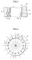
- annular laminated stack 2 has a plurality of caulked portions wherein each recess 8a" is formed to have a substantially trapezoid shape in an increased scale in cross section.
- the right annular end plate 1a has a plurality of circumferentially equally spaced projections 7a", configured in a substantially rectangular shape in cross section, at which the annular end plate 1b is caulked to the right side of the annular laminated stack 2.
- the left side face of the annular laminated stack 2 is formed with a plurality of circumferentially spaced axially and outwardly extending projections 8b" at which the annular end plate 1b is caulked to the left side of the annular laminated stack 2 at the circumferentially spaced axial projections 8b".
- the annular end plates may have the second fixing means formed in the substantially same shape and size as the first fixing means of the annular laminated stack 2.
- FIG. 6 is a view for illustrating an example of a pattern of caulked portions formed in the electromagnetic steel sheet.
- the electromagnetic steel sheet is formed with sixteen caulked portions 8a".
- the number of caulked portions may involves a half of the above number of caulked portions, i.e., eight caulked portions, or a further half of the eight caulked portions, i.e., four caulked portions depending on various situations and, thus, the number of caulked portions may be preferably selected to have a suitable value in a range between 4 to 16 pieces.
- the caulked portions may be formed at circumferentially, substantially, equally spaced positions.
- the caulked portions By forming the caulked portions in such equally spaced positions, a stress may be uniformly dispersed in the electromagnetic steel sheet to maintain a balance in strength. Selecting the number of caulked portions in the above range, it is possible for the strength, provided by the caulked portions, of the electromagnetic steel sheet to be highly improved to provide an improved operating performance of the motor, while enabling a capability in fabricating the rotor with an excellent strength without causing complicated fabricating steps.
- the caulked portions may be suitably located in a circumferential area distanced from an inner circumferential periphery of each electromagnetic steel sheet by 7 to 30 % a radial length of each electromagnetic steel sheet relative to an outer circumferential periphery thereof.
- the strength, provided by the caulked portions, of the electromagnetic steel sheet can be increased to minimize a deformation of the rotor, for thereby improving the operating performance of the motor.
- each of the caulked portions has been shown as an elongated shape in a circumferential direction, each caulked portion may extends in the elongated shape in the radial direction of the electromagnetic steel sheet or the electromagnetic steel sheet may have caulked portions extending in mixed orientations.
- the annular laminated stack 2 of the electromagnetic steel sheets has a plurality of cutouts 10 which serve as respective swivel stops and which serve to transmit a torque, acting on the annular laminated stack, to the cylindrical core buck.
- the stack of the electromagnetic steel sheets per se has the indents and the cylindrical core buck has the associated plural protrusions.
- such a combination may be reversed in structure.
- correction of rotational balance of the rotor structure is an essential work to be done for allowing the rotor shaft to rotate in a stabilized fashion by taking a weight balance of a rotational body, i.e., the rotor structure.
- a weight balance of a rotational body i.e., the rotor structure.
- each of the annular end plates it is desired for each of the annular end plates to have an excessive marginal annular portion to be shaped to provide the weight balance.
- a permanent-magnet motor is constructed essentially of a permanent magnet, which serves as a source of generating magnetic flux forming a power source, with an increase in the number of the permanent magnets resulting in an increased power output of the magnet type motor.
- the presence of a body of the laminated steel plates, which incorporate plural permanent magnets allows the motor to provide a further increased power output.
- the steel plates should be formed of the electromagnetic steel sheet. The use of the electromagnetic steel sheets, each of which has both side surfaces are electrically insulated, is effective for restricting electric current to be generated in the electromagnetic steel sheets through which magnetic flux passes during rotation of the rotor structure, thereby lowering loss in the power output.
- the presence of the rotor structure wherein the annular laminated stack of the electromagnetic steel sheets are sandwiched between the annular end plates and fitted on the cylindrical core buck, provides a sufficient rigidity to avoid deformation of the rotor structure during operation of the motor.
- These component elements constitute essential parts which can not be missed in the rotor of an internal magnet rotor type motor.
- the connecting portion which interconnects the cylindrical core buck and the rotor shaft to one another, serves to provide a role to fix the desired component part to the rotor shaft.
- annular end plates are coupled to the annular laminated stack of the electromagnetic steel sheets which are caulked with the concave or convex portions, renders an assembling process to be simplified to provide an ease of quality control such as rigidity. Since, in this instance, each of the annular end plates has the convex projection or the concave recess each of which is held in mating engagement with the corresponding contoured caulked portion of the annular laminated stack of electromagnetic steel sheets, the annular end plates are enabled to be readily positioned relative to the core stack in a simplified fashion during fixing assembly. Also, the presence of the caulked portion in the annular laminated stack renders the assembling work efficiency to be improved while ensuring an increased rigidity.
- the use of the specific configuration wherein a part of the centrifugal force generated in each annular end plate is received in the core stack of the laminated electromagnetic steel sheets, renders the rotor structure to realize the motor which is enabled to safely rotate at an extremely high speed reaching to a ten thousand and several hundred revolutions per minute, i.e., at a speed nearly equal to 20,000 rpm, even with the use of the annular end plates which are made of stainless steel "SUS304" classified under JIS (Japanese Industrial Standard) with less mechanical rigidity.
- JIS Japanese Industrial Standard
Landscapes
- Engineering & Computer Science (AREA)
- Power Engineering (AREA)
- Iron Core Of Rotating Electric Machines (AREA)
- Permanent Field Magnets Of Synchronous Machinery (AREA)
- Manufacture Of Motors, Generators (AREA)
Abstract
Description
Claims (9)
- A rotor structure for a permanent-magnet motor, comprising:wherein each outer end surface of the annular laminated stack has a plurality of first contoured fixing portions (8a, 8a', 8a"; 8b, 8b', 8b"), and an inner surface of each of the annular end plates has a plurality of second contoured fixing portions (7a, 7a', 7a"; 7b, 7b', 7b"); andan annular laminated stack (2) of electromagnetic steel sheets incorporating therein permanent magnets;a pair of annular end plates (1a, 1b) between which the annular laminated stack is sandwiched;a cylindrical core buck (3) having its outer circumferential periphery carrying thereon the annular laminated stack and the annular end plates; anda rotor shaft (5) integrally connected to the cylindrical core buck to be rotatable therewith;
wherein the annular laminated stack and the annular end plates are fixedly coupled to one another by caulking at the first and second fixing portions. - The rotor structure according to claim 1, wherein the annular laminated stack (2) and the annular end plates (1a, 1b) are held on the cylindrical core buck (3) and fixed thereto by a C-ring (9) fitted thereto.
- The rotor structure according to claims 1 or 2, wherein the annular end plates (1a, 1b) and the annular laminated stack (2) are fixed to the cylindrical core buck (3) by caulking.
- The rotor structure according to any one of claims 1 to 3, wherein each of the annular end plates (1a, 1b) is made of non-magnetic material.
- The rotor structure according to claim 4, wherein each of the annular end plates (1a, 1b) is made of stainless steel.
- The rotor structure according to any of claims 1 to 5, wherein the first fixing portions (8a, 8a', 8a"; 8b, 8b', 8b") of the annular laminated stack (2) are located in a circumferential area distanced from an inner circumferential periphery of each electromagnetic steel sheet by 7 to 30 % a radial length of each electromagnetic steel sheet relative to an outer circumferential periphery thereof and at circumferentially, equally spaced positions.
- The rotor structure according to claim 6, wherein each of the first fixing portions (8a, 8a', 8a"; 8b, 8b', 8b") of the annular laminated stack is formed in a rectangular shape which has a first dimensional element of more than 1 mm and a second dimensional element of more than 2 mm, with a third dimensional element of a value equal to one to two times the thickness of each electromagnetic steel plate.
- The rotor structure according to any one of claims 1 to 5, wherein each of the second contoured fixing portions (7a, 7a', 7a"; 7b, 7b', 7b") of the annular end plate has substantially the same dimensional size as that of each of the first contoured fixing portion of the annular laminated stack.
- The rotor structure according to any one of claims 1 to 5, wherein each of the annular end plates has an excessive marginal portion for enabling a rotating balance of the rotor.
Applications Claiming Priority (2)
| Application Number | Priority Date | Filing Date | Title |
|---|---|---|---|
| JP2000296377A JP3661582B2 (en) | 2000-09-28 | 2000-09-28 | Rotor for magnet motor |
| JP2000296377 | 2000-09-28 |
Publications (3)
| Publication Number | Publication Date |
|---|---|
| EP1193827A2 true EP1193827A2 (en) | 2002-04-03 |
| EP1193827A3 EP1193827A3 (en) | 2002-07-31 |
| EP1193827B1 EP1193827B1 (en) | 2005-07-20 |
Family
ID=18778666
Family Applications (1)
| Application Number | Title | Priority Date | Filing Date |
|---|---|---|---|
| EP01122884A Expired - Lifetime EP1193827B1 (en) | 2000-09-28 | 2001-09-24 | Rotor structure for permanent-magnet motor |
Country Status (4)
| Country | Link |
|---|---|
| US (1) | US6727628B2 (en) |
| EP (1) | EP1193827B1 (en) |
| JP (1) | JP3661582B2 (en) |
| DE (1) | DE60112015T2 (en) |
Cited By (4)
| Publication number | Priority date | Publication date | Assignee | Title |
|---|---|---|---|---|
| DE10327292A1 (en) * | 2003-06-17 | 2005-02-03 | Siemens Ag | Electric machine |
| DE102005041352A1 (en) * | 2005-08-31 | 2007-03-01 | Siemens Ag | Permanently excited synchronous machine, has permanent magnets arranged in axially aligned magnet slots of rotor, where two permanent magnets are provided on each pole of rotor in circumferential direction |
| DE102005042543A1 (en) * | 2005-09-07 | 2007-03-15 | Siemens Ag | Permanent-magnet synchronous machine for slowly rotating wind power plant, has counterpart provided as fastening part at magnet wheel, which is formed from two disk-shaped units and aligned bars that run axially perpendicular |
| EP3432448A1 (en) * | 2017-07-21 | 2019-01-23 | Goodrich Actuation Systems SAS | Permanent magnet rotor for an electrical machine |
Families Citing this family (37)
| Publication number | Priority date | Publication date | Assignee | Title |
|---|---|---|---|---|
| JP3951905B2 (en) * | 2002-04-25 | 2007-08-01 | 日産自動車株式会社 | Magnetic steel sheet forming body for rotor core, rotor for built-in permanent magnet type rotating electric machine using the same, method for producing electromagnetic steel sheet forming body for rotor core, and permanent magnet built-in type rotating electric machine |
| JP2004129329A (en) * | 2002-09-30 | 2004-04-22 | Hitachi Koki Co Ltd | Permanent magnet commutator motor |
| CN100499322C (en) * | 2003-07-18 | 2009-06-10 | 雅马哈发动机株式会社 | Rotating electrical machine and electric vehicle having the same |
| TWI259638B (en) * | 2004-12-01 | 2006-08-01 | Ind Tech Res Inst | Structure of an electric motor |
| DE102005060118A1 (en) * | 2004-12-20 | 2006-07-06 | Danfoss Compressors Gmbh | Rotor for an electric motor |
| DE102005060116A1 (en) * | 2004-12-20 | 2006-07-06 | Danfoss Compressors Gmbh | Rotor for an electric motor |
| DE102005060117A1 (en) * | 2004-12-20 | 2006-07-06 | Danfoss Compressors Gmbh | Rotor with cover plate for securing a magnet in the rotor |
| CN1332500C (en) * | 2005-02-04 | 2007-08-15 | 艾纯 | Small-sized dipolar single-phase generator |
| US7285890B2 (en) * | 2005-03-30 | 2007-10-23 | Comprehensive Power, Inc. | Magnet retention on rotors |
| KR100664065B1 (en) * | 2005-06-20 | 2007-01-03 | 엘지전자 주식회사 | Magnet fixing structure of electric motor |
| JP4236056B2 (en) * | 2006-02-08 | 2009-03-11 | 三菱電機株式会社 | Magnet generator |
| US7696661B2 (en) * | 2006-04-12 | 2010-04-13 | Gm Global Technology Operations, Inc. | Stator for an electric motor and assembly method |
| US7385328B2 (en) * | 2006-05-23 | 2008-06-10 | Reliance Electric Technologies, Llc | Cogging reduction in permanent magnet machines |
| US8030816B2 (en) | 2006-06-06 | 2011-10-04 | Honda Motor Co., Ltd. | Motor and motor control device |
| JP2008271640A (en) | 2007-04-17 | 2008-11-06 | Honda Motor Co Ltd | Axial gap type motor |
| JP4707696B2 (en) | 2007-06-26 | 2011-06-22 | 本田技研工業株式会社 | Axial gap type motor |
| JP4961302B2 (en) | 2007-08-29 | 2012-06-27 | 本田技研工業株式会社 | Axial gap type motor |
| US7977843B2 (en) | 2007-10-04 | 2011-07-12 | Honda Motor Co., Ltd. | Axial gap type motor |
| JP4729551B2 (en) | 2007-10-04 | 2011-07-20 | 本田技研工業株式会社 | Axial gap type motor |
| US7906883B2 (en) | 2008-06-02 | 2011-03-15 | Honda Motor Co., Ltd. | Axial gap motor |
| JP4573251B2 (en) * | 2008-06-02 | 2010-11-04 | 本田技研工業株式会社 | Axial gap type motor |
| US8049389B2 (en) | 2008-06-02 | 2011-11-01 | Honda Motor Co., Ltd. | Axial gap motor |
| JP4678549B2 (en) | 2008-10-09 | 2011-04-27 | 本田技研工業株式会社 | Axial gap type motor |
| US20100231064A1 (en) * | 2009-03-11 | 2010-09-16 | Gm Global Technology Operations, Inc. | Balance ring for a vehicular electric machine |
| JP2010233291A (en) * | 2009-03-26 | 2010-10-14 | Aisin Seiki Co Ltd | Motor rotor |
| US9847704B2 (en) * | 2015-02-19 | 2017-12-19 | GM Global Technology Operations LLC | Rotor assembly and method of manufacture for electric machines having multiple magnet lengths |
| KR102106294B1 (en) * | 2018-09-21 | 2020-05-04 | 주식회사 만도 | Vehicle Steering Apparatus |
| JP7234863B2 (en) * | 2019-08-26 | 2023-03-08 | 株式会社デンソー | Embedded magnet rotor |
| US11522436B2 (en) | 2019-10-15 | 2022-12-06 | Darrell Schmidt Enterprises, Inc. | Permanently magnetized enhanced generator |
| WO2021076428A1 (en) | 2019-10-15 | 2021-04-22 | Darrell Schmidt Enterprises, Inc. | Magnetic coupler |
| DE102020203483A1 (en) * | 2020-03-18 | 2021-09-23 | Mahle International Gmbh | Rotor of an electric motor |
| JP7012815B1 (en) | 2020-12-24 | 2022-01-28 | 三菱電機株式会社 | Manufacturing method of armature core, rotary electric machine, elevator hoist, and armature core |
| DE102021108893A1 (en) * | 2021-04-09 | 2022-10-13 | Schaeffler Technologies AG & Co. KG | A method of mechanically joining two components firmly, a rotor of a rotary electric machine, a method of manufacturing a rotor of a rotary electric machine, and a rotary electric machine |
| EP4312351A1 (en) * | 2022-07-28 | 2024-01-31 | Airbus Operations, S.L.U. | Improved internal cooling systems for e-machines |
| JPWO2024070043A1 (en) * | 2022-09-28 | 2024-04-04 | ||
| JPWO2024195827A1 (en) * | 2023-03-23 | 2024-09-26 | ||
| JP2025116659A (en) * | 2024-01-29 | 2025-08-08 | 株式会社小松製作所 | Rotor, rotating electric machine and work machine |
Family Cites Families (10)
| Publication number | Priority date | Publication date | Assignee | Title |
|---|---|---|---|---|
| US3671787A (en) * | 1971-08-16 | 1972-06-20 | Ibm | Laminated dynamoelectric machine having nonmagnetic lamina for structural support |
| US4160182A (en) * | 1977-07-27 | 1979-07-03 | Mitsui Mfg. Co., Ltd. | Laminated core manufacture |
| US4506181A (en) * | 1984-03-02 | 1985-03-19 | General Electric Company | Permanent magnet rotor with complete amortisseur |
| FR2655784B1 (en) * | 1989-12-08 | 1992-01-24 | Alsthom Gec | FLOW CONCENTRATION MAGNET MOTOR. |
| JPH0614481A (en) * | 1992-06-25 | 1994-01-21 | Mitsubishi Electric Corp | Armature iron core |
| US5363937A (en) * | 1992-10-19 | 1994-11-15 | Lmc Operating Corp. | Battery operated tracked vehicle |
| US5829120A (en) * | 1993-02-15 | 1998-11-03 | Fanuc, Ltd. | Method for manufacturing a rotor for synchronous motor |
| US6047460A (en) * | 1996-01-23 | 2000-04-11 | Seiko Epson Corporation | Method of producing a permanent magnet rotor |
| US5894182A (en) * | 1997-08-19 | 1999-04-13 | General Electric Company | Motor with rotor and stator core paired interlocks |
| JP2000184638A (en) * | 1998-12-18 | 2000-06-30 | Calsonic Kansei Corp | Motor |
-
2000
- 2000-09-28 JP JP2000296377A patent/JP3661582B2/en not_active Expired - Fee Related
-
2001
- 2001-09-24 DE DE60112015T patent/DE60112015T2/en not_active Expired - Lifetime
- 2001-09-24 EP EP01122884A patent/EP1193827B1/en not_active Expired - Lifetime
- 2001-09-27 US US09/963,552 patent/US6727628B2/en not_active Expired - Fee Related
Cited By (5)
| Publication number | Priority date | Publication date | Assignee | Title |
|---|---|---|---|---|
| DE10327292A1 (en) * | 2003-06-17 | 2005-02-03 | Siemens Ag | Electric machine |
| DE102005041352A1 (en) * | 2005-08-31 | 2007-03-01 | Siemens Ag | Permanently excited synchronous machine, has permanent magnets arranged in axially aligned magnet slots of rotor, where two permanent magnets are provided on each pole of rotor in circumferential direction |
| DE102005042543A1 (en) * | 2005-09-07 | 2007-03-15 | Siemens Ag | Permanent-magnet synchronous machine for slowly rotating wind power plant, has counterpart provided as fastening part at magnet wheel, which is formed from two disk-shaped units and aligned bars that run axially perpendicular |
| EP3432448A1 (en) * | 2017-07-21 | 2019-01-23 | Goodrich Actuation Systems SAS | Permanent magnet rotor for an electrical machine |
| US11152826B2 (en) | 2017-07-21 | 2021-10-19 | Goodrich Actuation Systems S.A.S. | Rotors for electrical machines |
Also Published As
| Publication number | Publication date |
|---|---|
| JP2002112481A (en) | 2002-04-12 |
| DE60112015D1 (en) | 2005-08-25 |
| US20020036440A1 (en) | 2002-03-28 |
| EP1193827B1 (en) | 2005-07-20 |
| US6727628B2 (en) | 2004-04-27 |
| DE60112015T2 (en) | 2006-04-13 |
| EP1193827A3 (en) | 2002-07-31 |
| JP3661582B2 (en) | 2005-06-15 |
Similar Documents
| Publication | Publication Date | Title |
|---|---|---|
| US6727628B2 (en) | Rotor structure for permanent-magnet motor | |
| EP1283581B1 (en) | Rotor for permanent magnet motor | |
| EP1895638B1 (en) | Rotary electric machine | |
| EP2200154B1 (en) | Axial gap motor | |
| US7906883B2 (en) | Axial gap motor | |
| US7355311B2 (en) | Rotor of axial gap motor and method of producing same | |
| US6967420B2 (en) | Electrical machine having a rotor specially adapted to high speeds | |
| EP2184838B1 (en) | Axial gap type motor | |
| US20110273034A1 (en) | Axial gap motor | |
| US7019428B2 (en) | Induction motor and rotor therefor | |
| CN108696019B (en) | End plate for rotor of switched reluctance motor | |
| JP2002281722A (en) | Outer rotor motor and electric vehicle | |
| JPH0956092A (en) | Permanent magnet rotor | |
| EP1612912A1 (en) | Permanent magnet electric machine | |
| CN116231913A (en) | Rotor with supporting device, electric machine with rotor and motor vehicle with electric machine | |
| AU2020382759B2 (en) | Improved rotor assemblies for axial flux machines | |
| JP4556408B2 (en) | Claw pole type rotating machine | |
| CN114830493A (en) | Electric motor | |
| JP2004153975A (en) | Rotating electric machine rotor | |
| CN224204843U (en) | Motor rotor assembly, motor and vehicle | |
| US20220337143A1 (en) | Rotor of rotary electric machine | |
| JP4482900B2 (en) | Axial gap type motor | |
| JP3312475B2 (en) | Synchronous motor | |
| JP2009011067A (en) | Rotating electric machine | |
| WO2024195827A1 (en) | Rotor for reluctance motor and reluctance motor |
Legal Events
| Date | Code | Title | Description |
|---|---|---|---|
| PUAI | Public reference made under article 153(3) epc to a published international application that has entered the european phase |
Free format text: ORIGINAL CODE: 0009012 |
|
| 17P | Request for examination filed |
Effective date: 20010924 |
|
| AK | Designated contracting states |
Kind code of ref document: A2 Designated state(s): AT BE CH CY DE DK ES FI FR GB GR IE IT LI LU MC NL PT SE TR |
|
| AX | Request for extension of the european patent |
Free format text: AL;LT;LV;MK;RO;SI |
|
| PUAL | Search report despatched |
Free format text: ORIGINAL CODE: 0009013 |
|
| AK | Designated contracting states |
Kind code of ref document: A3 Designated state(s): AT BE CH CY DE DK ES FI FR GB GR IE IT LI LU MC NL PT SE TR |
|
| AX | Request for extension of the european patent |
Free format text: AL;LT;LV;MK;RO;SI |
|
| AKX | Designation fees paid |
Designated state(s): DE FR GB |
|
| 17Q | First examination report despatched |
Effective date: 20030701 |
|
| GRAP | Despatch of communication of intention to grant a patent |
Free format text: ORIGINAL CODE: EPIDOSNIGR1 |
|
| GRAS | Grant fee paid |
Free format text: ORIGINAL CODE: EPIDOSNIGR3 |
|
| GRAA | (expected) grant |
Free format text: ORIGINAL CODE: 0009210 |
|
| AK | Designated contracting states |
Kind code of ref document: B1 Designated state(s): DE FR GB |
|
| REG | Reference to a national code |
Ref country code: GB Ref legal event code: FG4D |
|
| REF | Corresponds to: |
Ref document number: 60112015 Country of ref document: DE Date of ref document: 20050825 Kind code of ref document: P |
|
| ET | Fr: translation filed | ||
| PLBE | No opposition filed within time limit |
Free format text: ORIGINAL CODE: 0009261 |
|
| STAA | Information on the status of an ep patent application or granted ep patent |
Free format text: STATUS: NO OPPOSITION FILED WITHIN TIME LIMIT |
|
| 26N | No opposition filed |
Effective date: 20060421 |
|
| PGFP | Annual fee paid to national office [announced via postgrant information from national office to epo] |
Ref country code: DE Payment date: 20130918 Year of fee payment: 13 |
|
| PGFP | Annual fee paid to national office [announced via postgrant information from national office to epo] |
Ref country code: FR Payment date: 20130910 Year of fee payment: 13 Ref country code: GB Payment date: 20130918 Year of fee payment: 13 |
|
| REG | Reference to a national code |
Ref country code: DE Ref legal event code: R119 Ref document number: 60112015 Country of ref document: DE |
|
| GBPC | Gb: european patent ceased through non-payment of renewal fee |
Effective date: 20140924 |
|
| REG | Reference to a national code |
Ref country code: DE Ref legal event code: R119 Ref document number: 60112015 Country of ref document: DE Effective date: 20150401 |
|
| REG | Reference to a national code |
Ref country code: FR Ref legal event code: ST Effective date: 20150529 |
|
| PG25 | Lapsed in a contracting state [announced via postgrant information from national office to epo] |
Ref country code: DE Free format text: LAPSE BECAUSE OF NON-PAYMENT OF DUE FEES Effective date: 20150401 Ref country code: GB Free format text: LAPSE BECAUSE OF NON-PAYMENT OF DUE FEES Effective date: 20140924 |
|
| PG25 | Lapsed in a contracting state [announced via postgrant information from national office to epo] |
Ref country code: FR Free format text: LAPSE BECAUSE OF NON-PAYMENT OF DUE FEES Effective date: 20140930 |