EP1193639A2 - A data code image reading apparatus - Google Patents
A data code image reading apparatus Download PDFInfo
- Publication number
- EP1193639A2 EP1193639A2 EP01120505A EP01120505A EP1193639A2 EP 1193639 A2 EP1193639 A2 EP 1193639A2 EP 01120505 A EP01120505 A EP 01120505A EP 01120505 A EP01120505 A EP 01120505A EP 1193639 A2 EP1193639 A2 EP 1193639A2
- Authority
- EP
- European Patent Office
- Prior art keywords
- data
- image
- image data
- code
- reading apparatus
- Prior art date
- Legal status (The legal status is an assumption and is not a legal conclusion. Google has not performed a legal analysis and makes no representation as to the accuracy of the status listed.)
- Granted
Links
Images


Classifications
-
- G—PHYSICS
- G06—COMPUTING OR CALCULATING; COUNTING
- G06K—GRAPHICAL DATA READING; PRESENTATION OF DATA; RECORD CARRIERS; HANDLING RECORD CARRIERS
- G06K7/00—Methods or arrangements for sensing record carriers, e.g. for reading patterns
- G06K7/10—Methods or arrangements for sensing record carriers, e.g. for reading patterns by electromagnetic radiation, e.g. optical sensing; by corpuscular radiation
- G06K7/10544—Methods or arrangements for sensing record carriers, e.g. for reading patterns by electromagnetic radiation, e.g. optical sensing; by corpuscular radiation by scanning of the records by radiation in the optical part of the electromagnetic spectrum
- G06K7/10821—Methods or arrangements for sensing record carriers, e.g. for reading patterns by electromagnetic radiation, e.g. optical sensing; by corpuscular radiation by scanning of the records by radiation in the optical part of the electromagnetic spectrum further details of bar or optical code scanning devices
- G06K7/10881—Methods or arrangements for sensing record carriers, e.g. for reading patterns by electromagnetic radiation, e.g. optical sensing; by corpuscular radiation by scanning of the records by radiation in the optical part of the electromagnetic spectrum further details of bar or optical code scanning devices constructional details of hand-held scanners
-
- G—PHYSICS
- G06—COMPUTING OR CALCULATING; COUNTING
- G06K—GRAPHICAL DATA READING; PRESENTATION OF DATA; RECORD CARRIERS; HANDLING RECORD CARRIERS
- G06K17/00—Methods or arrangements for effecting co-operative working between equipments covered by two or more of main groups G06K1/00 - G06K15/00, e.g. automatic card files incorporating conveying and reading operations
- G06K17/0022—Methods or arrangements for effecting co-operative working between equipments covered by two or more of main groups G06K1/00 - G06K15/00, e.g. automatic card files incorporating conveying and reading operations arrangements or provisions for transferring data to distant stations, e.g. from a sensing device
-
- G—PHYSICS
- G06—COMPUTING OR CALCULATING; COUNTING
- G06K—GRAPHICAL DATA READING; PRESENTATION OF DATA; RECORD CARRIERS; HANDLING RECORD CARRIERS
- G06K7/00—Methods or arrangements for sensing record carriers, e.g. for reading patterns
- G06K7/10—Methods or arrangements for sensing record carriers, e.g. for reading patterns by electromagnetic radiation, e.g. optical sensing; by corpuscular radiation
- G06K7/10544—Methods or arrangements for sensing record carriers, e.g. for reading patterns by electromagnetic radiation, e.g. optical sensing; by corpuscular radiation by scanning of the records by radiation in the optical part of the electromagnetic spectrum
- G06K7/10712—Fixed beam scanning
- G06K7/10722—Photodetector array or CCD scanning
-
- G—PHYSICS
- G06—COMPUTING OR CALCULATING; COUNTING
- G06K—GRAPHICAL DATA READING; PRESENTATION OF DATA; RECORD CARRIERS; HANDLING RECORD CARRIERS
- G06K7/00—Methods or arrangements for sensing record carriers, e.g. for reading patterns
- G06K7/10—Methods or arrangements for sensing record carriers, e.g. for reading patterns by electromagnetic radiation, e.g. optical sensing; by corpuscular radiation
- G06K7/10544—Methods or arrangements for sensing record carriers, e.g. for reading patterns by electromagnetic radiation, e.g. optical sensing; by corpuscular radiation by scanning of the records by radiation in the optical part of the electromagnetic spectrum
- G06K7/10821—Methods or arrangements for sensing record carriers, e.g. for reading patterns by electromagnetic radiation, e.g. optical sensing; by corpuscular radiation by scanning of the records by radiation in the optical part of the electromagnetic spectrum further details of bar or optical code scanning devices
- G06K7/1095—Methods or arrangements for sensing record carriers, e.g. for reading patterns by electromagnetic radiation, e.g. optical sensing; by corpuscular radiation by scanning of the records by radiation in the optical part of the electromagnetic spectrum further details of bar or optical code scanning devices the scanner comprising adaptations for scanning a record carrier that is displayed on a display-screen or the like
Definitions
- This invention relates to a data code image reading apparatus for optically reading a data code image.
- U.S.P. Nos. 5,414,251 and 5,659,167 disclose such data code image readers for POS systems.
- the data code image reader disclosed in U.S.P. NO. 5,414,251 processes the output of selected images via pattern recognition means, and images recognized to contain decodable optical information are displayed and highlighted by a display.
- the data code image reader disclosed in U.S.P. No. 5,659,167 displays data code image matrix or two-dimensional bar code. The image is continuously updated as the data form filled with entered data. Using the display and an input unit such as a keyboard, digitizer or scanner, the decoded data can be edited to add, modify or delete data while observing the resulting data code image.
- the aim of the present invention is to provide a superior data code image reading apparatus.
- a first aspect of the present invention provides a data code image reading apparatus comprising: optical reading means for reading data code image as image data; display means for displaying said image data; data input means for inputting data relating said image data; and storing means for storing said image data and said data with relationship therebetween.
- a second aspect of the present invention provides a data code image reading apparatus based on the first aspect, further comprises outputting means for outputting said image data and said data with said relationship.
- a third aspect of the present invention provides a data code image reading apparatus based on the first aspect, wherein said data input means comprises a transparent touch panel on a displaying surface of said display means.
- a fifth aspect of the present invention provides a data code image reading apparatus based on the fourth aspect, wherein said data input means further includes a memory and a character conversion mode for converting a set of characters previously inputted by said data input means into another type of character.
- a sixth aspect of the present invention provides a data code image reading apparatus comprising: optical reading means for reading data code image as image data; display means for displaying said image data; data input means for inputting data relating said image data; and outputting means for outputting said image data and said data with relationship therebetween.
- a seventh aspect of the present invention provides a data code image reading apparatus based on the sixth aspect, further comprises storing means for storing said image data and said data to supply said image data and said data to said outputting means with relationship therebetween.
- an eighth aspect of the present invention provides a data code image reading apparatus based on the first aspect, further comprises: recognizing and decoding means for recognizing and decoding said image data; and judging means for judging whether said image data is correctly decoded, wherein said data input means operates to input said data relating said image data when said image data is incorrectly decoded, and said storing means stores the decoded data in place of said image data when said image data is correctly decoded.
- QR quick response
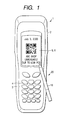
- the portable reader 1 includes a portable case 2.
- the portable case 2 has a grip portion 20.
- a keyboard 3 including a plurality of keys 4 is provided.
- a liquid crystal display (LCD) 5 above (in the drawing) the keyboard 3.
- a touch panel 6 is provided which is transparent to show the displayed image therethrough.
- the tip of the case 2 has an opening portion 21, and a lens 7 is fixed to the opening portion 21 as shown in Fig. 2.
- a two-dimensional CCD (charged-coupled device) 8 (shown in Fig. 3) is provided on the optical axis determined by the lens 7, a two-dimensional CCD (charged-coupled device) 8 (shown in Fig. 3) is provided on the optical axis determined by the lens 7, a two-dimensional CCD (charged-coupled device) 8 (shown in Fig. 3) is provided.
- An image illuminated by an illumination LED (light-emitting diode) 14 is projected on the two-dimensional CCD 8 through an optical unit including the lens 7.
- Fig. 3 shows a data processing system of the portable reader according to the present invention.
- the data processing system includes the two-dimensional CCD 8, the illumination LED 14, a microprocessor 9, the liquid crystal display 5, the touch panel 6 for generating touched position data in response to touch to the surface of the touch panel 6, a key code generation circuit 15 for generating a key code in response to the keyboard 3, an IrDA interface circuit 16 for communicating with an external unit in accordance with a protocol defined by the IrDA (Infrared Data Association) standard, and a secondary battery 17 such as Ni-Cd battery for supplying an electronic power to the data processing system.
- IrDA Infrared Data Association
- the microprocessor 9 includes a CPU (central processing unit) 10, a ROM (read-only memory) 11 for storing control programs, a RAM (random-access memory) 12, and an EEPROM (electrical erasable programmable read-only memory) 13.
- CPU central processing unit
- ROM read-only memory
- RAM random-access memory
- EEPROM electrical erasable programmable read-only memory
- the portable reader further includes a trigger key 4a on the side surface of the portable case 2 as a portion of the keyboard 3.
- the trigger key 4a starts the reading operation.
- QR code two-dimensional data code matrix
- an operator presses the opening portion 21 against a label with the QR code and operates the trigger key 4a.
- the illumination LED 14 turns on to illuminate the label.
- the reflected light is focused on the two-dimensional CCD 8 with the optical unit including the lens 7.
- the image on the two-dimensional LED 8 generates an image signal indicative of the two-dimensional pattern on two-dimensional CCD 8, that is, the QR code.
- the image signal is stored in the EEPROM 13 to store the two-dimensional pattern.
- the CPU 10 reads the image signal to decode the image signal as the QR code and displays the two-dimensional pattern of the QR code.
- the decoded QR code is supplied to an external unit through the IrDA interface circuit 16 if decoding the QR code is correctly decoded.
- the image signal is stored in the EEPROM 13.
- the keys 4 of the keyboard 3 are used for inputting a number and an alphabet or the like.
- a predetermined key operation that is, operation of a plurality of keys 4 in a predetermined order can input a kana (a Japanese system of syllabic writing).
- the CPU 10 displays the inputted number, alphabet, kana on the liquid crystal display 5.
- a kana may be inputted by converting a Roman character which is inputted by one to three alphabets because a Roman character is expressed with one to three alphabets.
- another predetermined key operation converts the kanas in the RAM 12 into a Chinese character or a phrase including a Chinese character and kanas.
- the CPU 10 displays the Chinese character in place of the kanas before conversion. That is, the CPU 10 can repeatedly convert one type of character into another type of characters.
- keyboard 3 is of a non-alphabet key type
- alphabets are also inputted by the predetermined key operation.
- a kana or the Chinese character is provided from the inputted alphabets as mentioned above.
- the CPU 10 stores the input character as character data or transmits the input character to the external unit through the IrDA interface circuit 16 as character data together with the image data regarding the data with relationship therebetween.
- the CPU 10 encodes the input character to QR code data.
- the QR code data is serially transmitted to an external unit through the IrDA interface circuit 16.
- the external unit generates the QR code (QR code bit map image, for example, printed image) in accordance with the transmitted QR code data.
- the position of the inputted number, alphabet, kana, or Chinese character can be changed upwardly, downwardly, right and left by operation of scroll keys out of the keys 4.
- the touch panel 6 on the liquid crystal display 5 detects the pressure thereon and a position of a pressed portion thereof. An operator draws a character on the touch panel 6 with a pen 18.
- the CPU 10 recognizes the handwritten character or the like. When a character is handwritten, the CPU 10 recognizes the presser position detected by the touch panel 7 and displays the handwritten character or the like on the liquid crystal display 5.
- the detected handwritten character is stored in the EEPROM 13 or transmitted to the external unit in the form of the bit map data, the run-length data, or the like together with the image data of the QR code from the EEPROM 13.
- the CPU 10 recognizes the detected handwritten characters and the recognized data is converted into character code data which is stored in the EEPROM 13 or transmitted to the external unit together with the image data of the QR code.
- step S1 the CPU 10 turns on the illumination LED14 and reads the QR code with the two-dimensional CCD 8 and displays the read QR code on the liquid crystal display 5 as shown in Fig. 1.
- step S2 the operator depresses a predetermined key for data addition on the keyboard 3.
- step S3 the CPU 10 enters the data addition mode.
- step S3 the CPU 10 requests a key input operation to judge whether the message is inputted with the touch panel 6 or the key 4.
- step S3 the CPU 10 enters the key input mode.
- step S4 the CPU 10 receives key inputting and converts the key code into character data of alphabet, into character data of kana if required, and into character data of Chinese character if required, and displays the additional data with the character data to represent a date, a message or the like on the liquid crystal display 5.
- step S3 If the operator selects the handwriting input operation (touch panel in step S3), the CPU 10 enters the touch input mode. In step S5, the CPU 10 receives handwriting input and displays the handwritten data as additional data on the liquid crystal display 5.
- step S6 the CPU 10 requires selection regarding storing to judge whether the added data is stored. If YES, the CPU 10 stores the image data of the QR code and the inputted message data with relationship therebetween as added data in step S7, and processing ends.
- step S6 if the storing operation is not required, processing ends to cancel the inputted message or the like to reenter it with correction or the like.
- a transmission operation is shown. This operation is periodically executed in response to timer interruption.
- the CPU 10 judges whether there is a request for transmission of the QR code and the message stored in the EEPROM 13.
- the CPU 10 transmits (YES in step S9), reads the image data of the QR code and the message added with relationship with the image data of the QR code from the EEPROM 13, and transmits the image data of the QR code and the added message data to the external unit with relationship therebetween in step S10, and processing ends. If the message data is not stored (the root from step S2 to step S6), only the image data is transmitted.
- the decoded code and the additional message may be stored in the EEPROM 13 and transmitted to the external unit when the message data is inputted or may be stored and transmitted without additional data when there is no input of message data.
- the reader can store the read image and message with relationship therebetween in the EEPROM 13. If the stored image data is read and displayed by an operator, the operator can know when and where the QR code is read, which article carried the QR code, or how degree the QR code is soiled from the added message displayed with the image data of the QR code. For this, the operator will not confuse the image data of the QR code with similar images of other QR codes.
- this portable reader is provided with key inputting and touch panel inputting of the message, so that the operator can select either of the key input or the handwriting input in accordance inclination of the operator.
- the message may be added only by the key input or only by the touch panel 6.
- the read image may be one-dimensional code such as a bar code, or other two-dimensional codes other than the QR code, or a picture image. If the one-dimensional code is read, the optical reading means may be a line sensor. The read image may be stored in the RAM 12.
- the reader may be not a portable type, that is, may be a situational type.
- Fig. 6 shows a modification of the data addition operation.
- the data addition operation according to the flow chart in Fig. 6 is substantially the same as that shown in Fig. 4. The difference is that transmission operation is further provided between the step S4 (step s5) and step S6. That is, after key input operation in step S4 and touch panel operation in step S5, the CPU 10 inquires of the operator whether transmission operation is needed. If the transmission operation is not needed, processing directly proceeds to step S6. If the transmission operation is needed, the CPU 10 transmits the image data and the additional data with relationship therebetween as added data to the external unit. In this case, the transmission portion of the IrDA interface circuit 16 should be directed to the external unit to transmit infrared beam to the external unit. However, if the transmission circuit uses a radio wave signal, the data can be transmitted at any timing if the reader is within the service range of the external unit.
- Fig. 7 is a modification of the example shown in Fig 6. That is, in place of process in step S2 in Fig. 6, steps S21 and S22 are executed. After reading the data code image, the CPU 10 recognizes and decodes the image data in step S21. Next, the CPU 10 judges whether the image data is correctly decoded in step S22. The data input operation in step S3 or step S5 is executed when the image data is incorrectly decoded. In the data storing operation in step S7, decoded data is stored in the EEPROM 13 in place of the image data, and the data addition operation is omitted when the image data is correctly decoded.
Landscapes
- Physics & Mathematics (AREA)
- Engineering & Computer Science (AREA)
- Electromagnetism (AREA)
- Theoretical Computer Science (AREA)
- General Physics & Mathematics (AREA)
- Toxicology (AREA)
- Artificial Intelligence (AREA)
- Computer Vision & Pattern Recognition (AREA)
- General Health & Medical Sciences (AREA)
- Health & Medical Sciences (AREA)
- General Engineering & Computer Science (AREA)
- Character Discrimination (AREA)
- Input From Keyboards Or The Like (AREA)
- Image Input (AREA)
- Measuring And Recording Apparatus For Diagnosis (AREA)
- Facsimile Scanning Arrangements (AREA)
- User Interface Of Digital Computer (AREA)
Abstract
Description
Claims (8)
- A data code image reading apparatus comprising:optical reading means for reading data code image as image data;display means for displaying said image data;data input means for inputting data relating said image data; andstoring means for storing said image data and said data with relationship therebetween.
- A data code image reading apparatus as claimed in claim 1, further comprising outputting means for outputting said image data and said data with said relationship.
- A data code image reading apparatus as claimed in claim 1, wherein said data input means comprises a transparent touch panel on a displaying surface of said display means.
- A data code image reading apparatus as claimed in claim 1, wherein said data input means comprises a keyboard having a plurality of keys and having a character mode and a non-character mode, wherein, in said character mode, said data input means inputs a character by a predetermined key operation.
- A data code image reading apparatus as claimed in claim 4, wherein said data input means further includes a memory and a character conversion mode for converting a set of characters previously inputted by said data input means into another type of character.
- A data code image reading apparatus comprising:optical reading means for reading data code image as image data;display means for displaying said image data;data input means for inputting data relating said image data; andoutputting means for outputting said image data and said data with relationship therebetween.
- A data code image reading apparatus as claimed in claim 6, further comprising storing means for storing said image data and said data to supply said image data and said data to said outputting means with relationship therebetween.
- A data code image reading apparatus as claimed in claim 1, further comprising:recognizing and decoding means for recognizing and decoding said image data; andjudging means for judging whether said image data is correctly decoded, wherein said data input means operates to input said data relating said image data when said image data is incorrectly decoded, and said storing means stores the decoded data in place of said image data when said image data is correctly decoded.
Applications Claiming Priority (2)
| Application Number | Priority Date | Filing Date | Title |
|---|---|---|---|
| JP2000257183A JP2002074261A (en) | 2000-08-28 | 2000-08-28 | Information code reader |
| JP2000257183 | 2000-08-28 |
Publications (3)
| Publication Number | Publication Date |
|---|---|
| EP1193639A2 true EP1193639A2 (en) | 2002-04-03 |
| EP1193639A3 EP1193639A3 (en) | 2002-07-17 |
| EP1193639B1 EP1193639B1 (en) | 2007-10-10 |
Family
ID=18745688
Family Applications (1)
| Application Number | Title | Priority Date | Filing Date |
|---|---|---|---|
| EP01120505A Expired - Lifetime EP1193639B1 (en) | 2000-08-28 | 2001-08-28 | A data code image reading apparatus |
Country Status (4)
| Country | Link |
|---|---|
| US (1) | US6637662B2 (en) |
| EP (1) | EP1193639B1 (en) |
| JP (1) | JP2002074261A (en) |
| DE (1) | DE60130855T2 (en) |
Families Citing this family (38)
| Publication number | Priority date | Publication date | Assignee | Title |
|---|---|---|---|---|
| US6561428B2 (en) * | 1997-10-17 | 2003-05-13 | Hand Held Products, Inc. | Imaging device having indicia-controlled image parsing mode |
| JP3876783B2 (en) * | 2002-07-19 | 2007-02-07 | 株式会社デンソーウェーブ | Information code reading method |
| JP4133298B2 (en) * | 2002-12-19 | 2008-08-13 | 株式会社リコー | Digital camera device |
| WO2004072811A2 (en) * | 2003-02-11 | 2004-08-26 | Michael Stefan Leoniak | Display having optical sensor for triggering secondary display |
| CN1792077B (en) * | 2003-05-19 | 2011-10-26 | 沃达丰集团股份有限公司 | Mobile communication terminal |
| US7638841B2 (en) * | 2003-05-20 | 2009-12-29 | Fairchild Semiconductor Corporation | Power semiconductor devices and methods of manufacture |
| US20050083413A1 (en) * | 2003-10-20 | 2005-04-21 | Logicalis | Method, system, apparatus, and machine-readable medium for use in connection with a server that uses images or audio for initiating remote function calls |
| DE202004007636U1 (en) * | 2004-05-10 | 2004-07-15 | Tesa Scribos Gmbh | Reading device for reading computer-generated lithographs |
| USD574830S1 (en) * | 2006-01-27 | 2008-08-12 | Datalogic, S.P.A. | Portable computer with bar code reader |
| EP2040200B1 (en) * | 2006-06-16 | 2014-08-13 | Pioneer Corporation | Two-dimensional code pattern, two-dimensional code pattern display device, and its reading device |
| CA120766S (en) * | 2007-05-18 | 2008-06-06 | Psion Teklogix Inc | Hand held computer |
| CA120767S (en) * | 2007-05-18 | 2008-06-06 | Psion Teklogix Inc | Hand held computer |
| USD606544S1 (en) | 2008-02-01 | 2009-12-22 | Datalogic Scanning Group S.R.L. | Coded information reader |
| USD599799S1 (en) | 2008-02-01 | 2009-09-08 | Datalogic Scanning Group S.R.L. | Coded information reader |
| USD613289S1 (en) | 2008-03-05 | 2010-04-06 | Datalogic Mobile S.R.L. | Code reader |
| USD643034S1 (en) | 2009-07-14 | 2011-08-09 | Datalogic Mobile S.R.L. | Portable computer with bar code reader |
| US8083149B2 (en) * | 2009-11-05 | 2011-12-27 | Hand Held Products, Inc. | Annotation of optical images on a mobile device |
| USD633915S1 (en) | 2009-11-27 | 2011-03-08 | Datalogic Mobile S.R.L. | Portable terminal |
| USD633502S1 (en) | 2009-11-27 | 2011-03-01 | Datalogic Mobile S.R.L. | Portable terminal |
| USD622726S1 (en) * | 2009-11-27 | 2010-08-31 | Datalogic Mobile S.R.L. | Portable terminal |
| TWI415017B (en) * | 2009-12-30 | 2013-11-11 | Inventec Appliances Corp | Point-of-sale management device |
| USD673955S1 (en) * | 2010-02-02 | 2013-01-08 | Psion Inc. | Handheld computer |
| US9112606B2 (en) * | 2010-12-15 | 2015-08-18 | Electronics And Telecommunications Research Institute | Method and apparatus for transmitting and receiving data using visible light communication |
| USD677663S1 (en) | 2011-11-04 | 2013-03-12 | Datalogic Ip Tech S.R.L. | Portable terminal |
| USD682277S1 (en) | 2011-12-30 | 2013-05-14 | Datalogic Ip Tech S.R.L. | Coded information reader |
| KR101873750B1 (en) * | 2012-02-02 | 2018-07-03 | 엘지전자 주식회사 | Mobile terminal and method for controlling thereof |
| US9754293B1 (en) | 2012-04-20 | 2017-09-05 | Lotmonkey, Llc | System and method for on-vehicle merchandising |
| US9582810B2 (en) * | 2012-04-20 | 2017-02-28 | John Wingle | Quick response information management system and method |
| USD723563S1 (en) | 2012-12-21 | 2015-03-03 | Datalogic Ip Tech S.R.L. | Reader of coded information |
| USD716307S1 (en) * | 2013-05-16 | 2014-10-28 | Datalogic Ip Tech S.R.L. | Portable terminal |
| GB201314642D0 (en) * | 2013-08-15 | 2013-10-02 | Summerfield Gideon | Image Identification System and Method |
| USD719574S1 (en) | 2014-01-09 | 2014-12-16 | Datalogic Ip Tech S.R.L. | Portable terminal |
| US9690968B2 (en) | 2015-05-17 | 2017-06-27 | William A. Wadley | Authenticated scannable code system |
| JP7082460B2 (en) * | 2017-07-20 | 2022-06-08 | カシオ計算機株式会社 | Mobile terminal |
| JP6850696B2 (en) | 2017-07-20 | 2021-03-31 | カシオ計算機株式会社 | Mobile terminal |
| JP6583742B2 (en) | 2017-07-20 | 2019-10-02 | カシオ計算機株式会社 | Mobile device |
| JP6829159B2 (en) * | 2017-07-20 | 2021-02-10 | カシオ計算機株式会社 | Mobile terminal |
| USD1091488S1 (en) * | 2024-07-05 | 2025-09-02 | Auma Riester Gmbh & Co. Kg | Remote control wireless |
Family Cites Families (4)
| Publication number | Priority date | Publication date | Assignee | Title |
|---|---|---|---|---|
| US5414251A (en) | 1992-03-12 | 1995-05-09 | Norand Corporation | Reader for decoding two-dimensional optical information |
| US5821523A (en) | 1992-03-12 | 1998-10-13 | Bunte; Alan G. | Combined code reader and digital camera using a common photodetector |
| US5513264A (en) | 1994-04-05 | 1996-04-30 | Metanetics Corporation | Visually interactive encoding and decoding of dataforms |
| EP0873013A3 (en) | 1996-11-05 | 2001-01-03 | Welch Allyn, Inc. | Decoding of real time video imaging |
-
2000
- 2000-08-28 JP JP2000257183A patent/JP2002074261A/en active Pending
-
2001
- 2001-08-24 US US09/935,768 patent/US6637662B2/en not_active Expired - Fee Related
- 2001-08-28 EP EP01120505A patent/EP1193639B1/en not_active Expired - Lifetime
- 2001-08-28 DE DE60130855T patent/DE60130855T2/en not_active Expired - Fee Related
Also Published As
| Publication number | Publication date |
|---|---|
| DE60130855D1 (en) | 2007-11-22 |
| EP1193639A3 (en) | 2002-07-17 |
| DE60130855T2 (en) | 2008-07-17 |
| JP2002074261A (en) | 2002-03-15 |
| EP1193639B1 (en) | 2007-10-10 |
| US20020023961A1 (en) | 2002-02-28 |
| US6637662B2 (en) | 2003-10-28 |
Similar Documents
| Publication | Publication Date | Title |
|---|---|---|
| US6637662B2 (en) | Data code image reading apparatus | |
| US6899273B2 (en) | Optical reader comprising soft key including permanent graphic indicia | |
| US7054487B2 (en) | Controlling and electronic device | |
| US5742279A (en) | Input/display integrated information processing device | |
| KR100411712B1 (en) | Information display control device and method and remote input device and method | |
| US20030001018A1 (en) | Optical reader comprising good read indicator | |
| US7229021B2 (en) | Indicia reader with synchronized light source and associated methods and computer program product | |
| US20030206150A1 (en) | Optical reader comprising keyboard | |
| EP1285329A1 (en) | Controlling an electronic device | |
| KR102480593B1 (en) | Inspection system and camera | |
| JP2006209324A (en) | Information reader | |
| JP3675289B2 (en) | Information code reader | |
| JP2006250998A (en) | Image display system | |
| JP2004110571A (en) | Procedure system, server device thereof, and form for electronic pen | |
| JP6039387B2 (en) | Display device | |
| JP4132225B2 (en) | Information code reading and creating device | |
| JPH0589280A (en) | Input device | |
| JP2006134160A (en) | Optical information reading device | |
| JP2003085474A (en) | Optical information reading device and information code output device | |
| JP4778720B2 (en) | Digital pen and handwriting input system | |
| JP2009026024A (en) | Mobile information reading terminal | |
| KR100601826B1 (en) | Active barcode system using mobile communication terminal and optical signal that can transmit barcode | |
| KR100823865B1 (en) | Multifunctional 2D Barcode Scanner | |
| JP4378894B2 (en) | Handy type information code reader | |
| JP2000207078A (en) | Character / symbol / code character transfer system |
Legal Events
| Date | Code | Title | Description |
|---|---|---|---|
| PUAI | Public reference made under article 153(3) epc to a published international application that has entered the european phase |
Free format text: ORIGINAL CODE: 0009012 |
|
| AK | Designated contracting states |
Kind code of ref document: A2 Designated state(s): AT BE CH CY DE DK ES FI FR GB GR IE IT LI LU MC NL PT SE TR |
|
| AX | Request for extension of the european patent |
Free format text: AL;LT;LV;MK;RO;SI |
|
| PUAL | Search report despatched |
Free format text: ORIGINAL CODE: 0009013 |
|
| AK | Designated contracting states |
Kind code of ref document: A3 Designated state(s): AT BE CH CY DE DK ES FI FR GB GR IE IT LI LU MC NL PT SE TR |
|
| AX | Request for extension of the european patent |
Free format text: AL;LT;LV;MK;RO;SI |
|
| RIC1 | Information provided on ipc code assigned before grant |
Free format text: 7G 06K 7/10 A, 7H 04N 1/32 B, 7G 06K 17/00 B |
|
| 17P | Request for examination filed |
Effective date: 20020913 |
|
| AKX | Designation fees paid |
Designated state(s): DE FR GB |
|
| GRAP | Despatch of communication of intention to grant a patent |
Free format text: ORIGINAL CODE: EPIDOSNIGR1 |
|
| GRAS | Grant fee paid |
Free format text: ORIGINAL CODE: EPIDOSNIGR3 |
|
| GRAA | (expected) grant |
Free format text: ORIGINAL CODE: 0009210 |
|
| AK | Designated contracting states |
Kind code of ref document: B1 Designated state(s): DE FR GB |
|
| REG | Reference to a national code |
Ref country code: GB Ref legal event code: FG4D |
|
| REF | Corresponds to: |
Ref document number: 60130855 Country of ref document: DE Date of ref document: 20071122 Kind code of ref document: P |
|
| ET | Fr: translation filed | ||
| REG | Reference to a national code |
Ref country code: GB Ref legal event code: 746 Effective date: 20080603 |
|
| PLBE | No opposition filed within time limit |
Free format text: ORIGINAL CODE: 0009261 |
|
| STAA | Information on the status of an ep patent application or granted ep patent |
Free format text: STATUS: NO OPPOSITION FILED WITHIN TIME LIMIT |
|
| 26N | No opposition filed |
Effective date: 20080711 |
|
| PGFP | Annual fee paid to national office [announced via postgrant information from national office to epo] |
Ref country code: DE Payment date: 20080912 Year of fee payment: 8 |
|
| PGFP | Annual fee paid to national office [announced via postgrant information from national office to epo] |
Ref country code: FR Payment date: 20080818 Year of fee payment: 8 |
|
| PGFP | Annual fee paid to national office [announced via postgrant information from national office to epo] |
Ref country code: GB Payment date: 20080903 Year of fee payment: 8 |
|
| GBPC | Gb: european patent ceased through non-payment of renewal fee |
Effective date: 20090828 |
|
| REG | Reference to a national code |
Ref country code: FR Ref legal event code: ST Effective date: 20100430 |
|
| PG25 | Lapsed in a contracting state [announced via postgrant information from national office to epo] |
Ref country code: FR Free format text: LAPSE BECAUSE OF NON-PAYMENT OF DUE FEES Effective date: 20090831 Ref country code: DE Free format text: LAPSE BECAUSE OF NON-PAYMENT OF DUE FEES Effective date: 20100302 |
|
| PG25 | Lapsed in a contracting state [announced via postgrant information from national office to epo] |
Ref country code: GB Free format text: LAPSE BECAUSE OF NON-PAYMENT OF DUE FEES Effective date: 20090828 |