EP1193572A2 - Installation of lower skive plate in the fuser section of an electrophotographic machine - Google Patents
Installation of lower skive plate in the fuser section of an electrophotographic machine Download PDFInfo
- Publication number
- EP1193572A2 EP1193572A2 EP01120672A EP01120672A EP1193572A2 EP 1193572 A2 EP1193572 A2 EP 1193572A2 EP 01120672 A EP01120672 A EP 01120672A EP 01120672 A EP01120672 A EP 01120672A EP 1193572 A2 EP1193572 A2 EP 1193572A2
- Authority
- EP
- European Patent Office
- Prior art keywords
- plate
- fuser
- skive
- housing
- section
- Prior art date
- Legal status (The legal status is an assumption and is not a legal conclusion. Google has not performed a legal analysis and makes no representation as to the accuracy of the status listed.)
- Withdrawn
Links
Images

Classifications
-
- G—PHYSICS
- G03—PHOTOGRAPHY; CINEMATOGRAPHY; ANALOGOUS TECHNIQUES USING WAVES OTHER THAN OPTICAL WAVES; ELECTROGRAPHY; HOLOGRAPHY
- G03G—ELECTROGRAPHY; ELECTROPHOTOGRAPHY; MAGNETOGRAPHY
- G03G15/00—Apparatus for electrographic processes using a charge pattern
- G03G15/20—Apparatus for electrographic processes using a charge pattern for fixing, e.g. by using heat
- G03G15/2003—Apparatus for electrographic processes using a charge pattern for fixing, e.g. by using heat using heat
- G03G15/2014—Apparatus for electrographic processes using a charge pattern for fixing, e.g. by using heat using heat using contact heat
- G03G15/2017—Structural details of the fixing unit in general, e.g. cooling means, heat shielding means
- G03G15/2028—Structural details of the fixing unit in general, e.g. cooling means, heat shielding means with means for handling the copy material in the fixing nip, e.g. introduction guides, stripping means
Definitions
- the present invention relates to the installation of the lower skive plate in the fuser section of a electrophotographic copier/printer apparatus and in one of its aspects relates to an assembly for removing and replacing the lower skive plate of the fuser section of an electrophotographic apparatus whereby the assembly prevents the blades on the skive plate from cutting or digging into the pressure roller of the fuser section while the lower skive plate is being installed.
- a continuous loop of photoconductor film is commonly used to transfer an image from an input section onto a receiving medium (e.g. a sheet of paper).
- a receiving medium e.g. a sheet of paper.
- the film is initially charged and then passes through an input section where an image is projected onto the charged film.
- the film then moves through a developing section where a toner is applied to the charged image, and on through an image transfer section where the image is transferred to the sheet of paper or other medium.
- the paper is subsequently passed through a fuser section where the toner forming the image is fixed to the paper by elevated temperature and pressure. This is typically accomplished by passing the paper between two, opposed rollers in the fuser section, i.e. a pressure roller and a fuser roller, one of which is heated.
- skive plates i.e. upper and lower skive plates
- skive plates are normally provided to strip the paper off the rollers (i.e. fuser and pressure rollers, respectively) after the toner is fused onto the paper.
- Each plate carries a plurality of thin, extremely sharp "skives” (i.e. blades) (e.g. 0.004 inches thick) which effectively ride on its respective roller.
- These plates are rigidly mounted near the rollers at a precise location and angle to provide the proper stripping force without digging or gouging into the roller.
- the skive plates are frequently removed and then reinstalled. During this operation, the skive plate must be guided so that the sharp skives do not gouge the roller.
- a cooling grid which is used for cooling the paper as it comes off the rollers, is an integral part of the lower skive plate in prior art machines of this type and is coupled to the cooling air duct by a gasket which exerts a high frictional force on the underside of the lower skive plate. This frictional contact with the gasket makes it difficult to slide the lower skive plate smoothly out of and into its operable position.
- the present invention provides a fuser section for an electrophotographic apparatus which includes a lower skive plate which, in turn, can be easily and quickly installed in and removed from within the fuser section without the risk of accidentally damaging the fuser roller and the method for installing the skive plate in the fuser section.
- the lower skive plate has a plurality of skives (i.e. sharp blade-like elements) thereon which are designed to ride on a fuser roller in the fuser section and strip sheets of paper off the fuser roller as they pass thereover.
- the skive plate has a forward and a rear latch pin on each side thereof.
- the plate is positioned within the housing of the fuser section so that the plate is above the fuser roller in a substantially horizontal position.
- the forward latch pins are positioned into respective guide tracks of a guide assembly on the fuser section.
- the skive plate is moved forward and downward (preferably at about a 45° angle) toward said fuser roller while keeping the plate in a relative horizontal position. This positioning keeps the skives clear of said fuser roller as the plate is being installed.
- the rear latch pins on said skive plate are latched to the fuser section by releasable, spring-biased rear detents therein. It is important that the rear pins are latched in the fuser section before the forward latch pins are latched which further insures that the technician installing the plate will not inadvertently tip the plate forward whereupon the sharp skives could contact and seriously damage the fuser roller.
- the front on the skive plate is then moved down through the remaining short distance to latch the forward latch pins in the releasable, spring-biased forward detents in the housing thereby securing said skive plate in said fuser section in its operable position with the skives now riding on said fuser roller.
- the procedure is merely reversed. By releasing and raising the front of the skive plate first, the danger of the skives gouging into the fuser roller is eliminated.
- the fuser section of present invention includes a cooling grill which is fixed within the housing adjacent the downstream side of the fuser roller.
- the present skive plate has a recess across a portion of the rear thereof which is adapted to lie over the cooling grill when the skive plate is in its operable position within the housing to thereby allow air from said cooling grill to flow through the skive plate to cool the sheets of paper as they pass over the skive plate. This eliminates the need for perforating a section of the skive plate and then frictionally coupling the plate to a source of cooling air which was required in known fuser sections of this type.
- a typical electrophotographic apparatus or machine 10 e.g. copier, duplicator, printer
- an endless photoconductor member 11 e.g. photographic film
- a copy medium e.g. a sheet S of paper
- the paper S is then fed between a fusing roller 21 and a pressure roller 22 in fuser section 20 to fix the toner image on the paper S before the paper exits the machine.
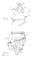
- FIG. 2 is a simplified, sectional view of a typical, prior art fuser section 20 of the type found in a electrophotographic machine 10 such as that illustrated in FIG. 1.
- fuser section 20 is comprised of a frame or housing 25 in which pressure roller 22 and fuser roller 21 are rotatably mounted.
- An upper skive plate 26 and a lower skive plate 27 carry a plurality of skives (unnumbered) which, in turn, are positioned to effectively ride on pressure roller 22 and fuser roller 21, respectively.
- These skives are thin blades (e.g. 0.004 inch thick) and are extremely sharp and are designed to strip the paper S from the respective rollers as the paper passes therethrough.
- Lower skive plate 27 of the prior art fuser section 20 has a grill-like, perforated portion 28 through which cooling air flows to cool paper S as it exits from the heated fuser roller 21.
- the lower side of the grill-like portion 28 is coupled to a cooling air, supply duct 29 by means of a sliding, frictional fit with gasket 30.
- Lower plate 27 is removed by moving the plate towards the nip between rollers 21, 22 to move a slot on the rear of the plate off a pin to release the plate and then pulling it in the other direction across the top of gasket 24. Plate 27 is installed in the same manner but using reverse steps.
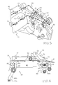
- FIG. 4 illustrates a portion of the present fuser section of an electrophotographic machine with some components removed for clarity.
- fuser section 20 of the present invention is comprised of a frame 30 in which pressure roller 22 and fuser roller 21 are mounted for rotation.
- a cooling grid 31 is mounted in the frame 30 downstream from rollers 21, 22 and has a plurality of openings 32 (only some numbered for clarity) for the distribution of cooling air over the lower side of a sheet of paper (not shown) after the paper has passed through the nip between the fuser (i.e. heated) roller 21 and the pressure roller 22. Cooling air is fed to grid 31 through inlet 33 which, in turn, is connected to an air source by a conduit (not shown).
- Lower skive plate 35 is positioned and secured in housing 30 as shown in FIG. 4.
- Lower skive plate 35 is comprised of a base plate 36 having handles 37 at either end thereof.
- An elongated recess 38 is provided along a portion of the rear of base plate 36 which aligns with grid 31 to allow cooling air to contact the sheet of heated paper as it exits rollers 21, 22 and skive plate 35 when the lower skive plate is in its latched, operable position (FIG. 4).
- Base plate 36 also has an elongated slot 39 which extends substantially across the width thereof and which is adapted to receive decurler roller 40 (FIG. 4) when lower skive plate is in its operable position.
- the forward portion 42 of base plate 36 is angled downward at an acute angle (e.g. about 35°) and carries one or more spaced skives 41 (seven shown).
- Skives 41 are thin (e.g. 0.004 inches) blade-like members which are very sharp and which are adapted to strip a sheet of paper off fuser roller 21 and thereby keep it from sticking thereto.
- Base plate 35 has a downward extending side 43 at either end thereof, each of which carry a forward pin 44 and a rear pin 45 (only one side shown in FIG. 3).
- a substantially rectangular opening 46 is provided in each of the handles 37 for a purpose to be described later.
- FIGS. 5 and 6 The mechanism for releasably securing lower skive plate 35 in its proper position within housing 30 is best seen in FIGS. 5 and 6.
- This mechanism is comprised of a pair of forward detents 48 (one on each side of housing 30) and a matching pair of rear detents 49. Since both sides of the latching mechanism is basically a mirror-image of the other, only the components on one side will be described in detail.
- Forward detent 48 is comprised of a pivoted arm 48b having a recess 48c near its upper end and rear detent 49 is comprised of a pivoted arm 49b having a multi-angled recess 49c near its upper end which are normally biased toward their latched positions by springs 48a, 49a, respectively.
- guide assembly 50 Secured to housing 30 adjacent the forward detent 49 is guide assembly 50 which, in turn, is comprised a forward guide element 51 and a spaced, rearward guide element 52.
- Forward element 51 has a first guide surface (i.e. slot defining a track 53) which is precisely angled (e.g. 45°) to guide and direct forward latch pin 44 into forward detent 48 during the installation of the skive plate.
- Forward guide element 51 also has a second, angled guide surface 53a for a purpose described below.
- Rearward guide element 52 has a guide surface or ramp 54 thereon which cooperates with second guide surface 53a as will be more fully discussed below.
- an angled tab 60 is provided on the underside of plate 35 which contacts the decurler roller 40 (FIG. 4) during the initial stages of installation.
- the plate To install lower skive plate 35 into housing 30, the plate is positioned onto the tops of the forward elements 51 of vertical guides 50 and is moved forward. It is desirable to keep the plate as horizontal as possible during installation to protect the rollers from the skives. As the openings 46 in handles 37 align with their respective rearward guide elements 52, the plate 35 will drop whereupon forward pins 44 will enter the upper end of the tracks 53 in forward guide elements 51 thereby guiding the tips of skives 41 downward at a 45 degree angle onto fuser roller 21.
- openings 46 on handles 37 contacts the ramps 54 on respective rearward elements 52 while the forward edges of the handles ride along second guide surfaces 53a on element 51, thereby requiring the technician to keep the rear of the skive plate low and substantially parallel to the frame 30 as he installs the plate.
- the contact between the plate 35 and ramps 54 and guide surfaces 53a require the technician to lower the rear of plate 35 towards rear detents 49 before the front pins can be captured by forward detents 48.
- the angled underside of recess 49c provides a lead into the recess but is flat enough to engage the top of pin 45 in much the same way as a flat surface of a stationary slot would, thereby preventing the detents 49 from being unlatched by accidentally lifting the rear of plate 35.
- the detents 49 are relatively short so that rear pins 45 can be lowered into recesses 49c near the end of the installation operation without binding the pins. After the rear pins 45 are securely latched by rear detents 49, the lowering of the front of the plate 35 is continued until forward pins 44 are latched within detents 48 and the installation of skive plate 35 is complete.
Landscapes
- Physics & Mathematics (AREA)
- General Physics & Mathematics (AREA)
- Fixing For Electrophotography (AREA)
- Electrophotography Configuration And Component (AREA)
Abstract
Description
- FIG. 1
- is a schematic view of an electrophotographic apparatus (e.g. copier/printer machine) in which the present invention can be incorporated;
- FIG. 2
- is a simplified, sectional view of the fuser section lying within line 2-2 of FIG. 1 showing prior art skive plates mounted in an operable position;
- FIG. 3
- is a perspective view of the lower skive plate of the present invention;
- FIG. 4
- is a perspective view of a portion of the fuser section of the present invention with the lower skive plate of FIG. 3 installed therein;
- FIG. 5
- is a perspective, enlarged view of one end of the latching assembly of FIG. 4, partly broken away, illustrating the positioning of the lower skive plate, shown in dotted lines, in an initial installation position and a final installed position; and
- FIG. 6
- is an enlarged, sectional view, partly broken away, of the latching assembly of the present invention with the lower skive plate of FIG. 3 in a latched, operable position.
- 10
- electrophotographic machine
- 11
- photoconductor member
- 12
- charging station
- 13
- exposure/input station
- 14
- developing station
- 15
- transfer station
- 16
- erase/claim section
- 20
- fuser section
- 21
- fuser roller
- 22
- pressure roller
- 24
- gasket
- 25
- frame/housing
- 26
- upper skive plate
- 27
- lower skive plate
- 28
- grill-like portion
- 29
- supply duct
- 30
- frame
- 31
- cooling grid
- 32
- openings
- 33
- inlet
- 35
- lower skive plate
- 36
- base plate
- 37
- handle
- 38
- elongated recess
- 39
- elongated slot
- 40
- decurler roller
- 41
- skive
- 42
- forward portion
- 43
- side
- 44
- pin
- 45
- pin
- 46
- opening
- 48
- forward detent
- 48a
- spring
- 48b
- pivoted arm
- 48c
- recess
- 49
- rear detent
- 49a
- spring
- 49b
- pivoted arm
- 49c
- recess
- 50
- guide assembly
- 51
- forward guide element
- 52
- rearward guide element
- 53
- track
- 53a
- angled guide surface
- 54
- ramp
- 60
- angled tab
- 66
- stop
- S
- Sheet
Claims (13)
- A fuser section (20) for an electrophotographic apparatus, said fuser section (20) comprising:a housing having two sides (30);a fuser roller (21) rotatably mounted in said housing;a skive plate (35) comprising;a base plate (36) having a front, rear, and two sides;a plurality of skives (41) mounted on and spaced across said front of said base plate (36), said skives (41) positioned to ride on said fuser roller (21) when said skive plate (35) is in its operable position within said housing to thereby strip a sheet of paper (S) off said fuser roller (21) as said sheet (S) passes over said fuser roller (21); anda forward latch pin (44) and a rear latch pin (45) mounted on each of said two sides of said base plate (36);a guide assembly (50) on said housing for guiding said skive plate (35) to its operable position within said housing while preventing said skives (41) from contacting and damaging said fuser roller (21) during installation; anda latching mechanism on said housing for releasably latching said forward and rear latch pins to said housing when said skive plate is in its operable position within said housing.
- The fuser section of claim 1 wherein said latching mechanism comprises:a forward releasable latch (48) on each of said two sides of said housing and adapted to receive respective, said forward latch pins on said skive plate; anda rear releasable latch (49) on each of said two sides of said housing and spaced from said respective, forward releasable latches and adapted to receive respective, said rear latch pins on said skive plate.
- The fuser section of claim 2 wherein said forward releasable latch (48) comprises:a first arm pivotably (48b) mounted on said housing having a recess (48c) near its upper end adapted to receive said forward latch pin (44) on said skive plate when said skive plate (35) is in its operable position within said housing; anda spring (48a) normally biasing said first arm (48b) toward its latched position;and wherein said rear releasable latch (49) comprises:a second arm pivotably (49b) mounted in said housing and having a recess (49c) adapted to receive said rear latch pin (45) on said skive plate (35) when said skive plate (35) is in its operable position within said housing; anda spring (49a) normally biasing said second arm (49b) toward its latched position.
- The fuser section of claim 3 wherein said guide assembly (5d) comprises:a forward guide element (51) positioned on each of said two sides of said housing adjacent said fuser roller (21), said forward element having a track (53) therein adapted to guide said forward latch pin (44) downward towards said fuser roller (21) as said skive plate (35) is being installed; anda rear guide element (52) positioned on each of said two sides of said housing andspaced from its respective said forward guide element.
- The fuser section of claim 4 wherein said track (53) in said forward element is inclined at an acute angle with respect to the vertical.
- The fuser section of claim 5 wherein said angle is about 45°.
- The fuser section of claim 5 including a cooling grid (31) positioned within said housing downstream and adjacent said fuser roller; and wherein
said skive plate having a recess (38) across a portion of said rear of said base plate, said recess adapted to lie over said cooling grill when said skive plate is in its operable position within said housing to thereby allow air from said cooling grill to flow through said base plate to cool said sheet of paper (S) as said paper (S) passes over said base plate (36). - A skive plate (35) for stripping a sheet of paper (S) off a roller in a fuser section (20) of an electrophotographic apparatus, said skive plate (35) comprising:a base plate (36) having a front, rear, and two sides;a plurality of skives (41) mounted on and spaced across said front of said base plate (36), said skives (41) positioned to ride on said roller (21) when said skive plate (35) is in its operable position within said fuser section (20); anda forward latch pin (44) mounted on and extending from each of said two sides of said base plate (36), said forward latch pin (44) being adapted to be received by a respective, forward latching detent (48) in said fuser section (20);a rear latch pin (45) mounted on and extending from each of said two sides of said base plate (36); said rear latch pin (45) being spaced from said forward latch pin andbeing adapted to be received by a respective, rear latching detent (49) in said fuser section (20); anda recess (38) extending across a portion of said rear of said base plate and adapted to lie over a cooling grill (31) when said skive plate (35) is in its operable position within said housing.
- The skive plate (35) of claim 8 including:a tab (60) extending downward from the underside of said front of said base plate (36), said tab (60) adapted to engage a decurler roller (40) in said fuser section (20) to prevent said skives (41) from contacting said fuser roller (21) during installation.
- A method for installing a skive plate (35) into the fuser section (20) of an electrophotographic apparatus wherein said fuser section (20) has a fuser roller (21) mounted therein, said skive plate (35) having a plurality of skives (41) and forward (44) and rear (45) latch pins thereon, said method comprising:positioning said forward latch pins (44) into respective guide tracks (48) provided on said fuser section (20);moving said skive plate (35) forward toward said fuser roller (21) to move said forward latch pins (44) forward and downward in said guide tracks while maintaining said skive plate (35) in a relative horizontal position thereby maintaining said skives (41) clear of said fuser roller (21) as said plate (35) is being moved toward its operable position within said fuser section (20);latching said rear latch pins (45) on said skive plate (35) in said fuser section (20) before latching said forward latch pins (44), andlatching said rear latch pins (45) on said skive plate (35) in said fuser section (20) thereby releasably securing said skive plate (35) in said fuser section (20) with said skives (41) riding on said fuser roller (21).
- The method of claim 10 wherein said forward latch pins (44) are moved forward and downward in said guide tracks at an angle of about 45°.
- The method of claim 11 wherein said skives (41) are maintained out of contact with said fuser roller (21) until said rear latch pins (45) have been latched to said fuser section (20).
- The method of claim 12 including removing said skive plate (35) from said fuser section (20) which, in turn, includes:unlatching said front latch pins (44) from said fuser section (20) and lifting said skives (41) up and away from said fuser roller (21);unlatching said rear latch pins (45) from said fuser section (20) and moving said skive plate (35) upward while maintaining said skive plate (35) in a substantial horizontal position to remove said skive plate (35) from said fuser section (20).
Applications Claiming Priority (2)
| Application Number | Priority Date | Filing Date | Title |
|---|---|---|---|
| US671712 | 1984-11-15 | ||
| US09/671,712 US6295436B1 (en) | 2000-09-27 | 2000-09-27 | Installation of lower skive plate in the fuser section of an electrophotographic machine |
Publications (2)
| Publication Number | Publication Date |
|---|---|
| EP1193572A2 true EP1193572A2 (en) | 2002-04-03 |
| EP1193572A3 EP1193572A3 (en) | 2004-12-29 |
Family
ID=24695589
Family Applications (1)
| Application Number | Title | Priority Date | Filing Date |
|---|---|---|---|
| EP01120672A Withdrawn EP1193572A3 (en) | 2000-09-27 | 2001-09-03 | Installation of lower skive plate in the fuser section of an electrophotographic machine |
Country Status (5)
| Country | Link |
|---|---|
| US (1) | US6295436B1 (en) |
| EP (1) | EP1193572A3 (en) |
| JP (1) | JP2004510205A (en) |
| AU (1) | AU2001284847A1 (en) |
| WO (1) | WO2002027412A1 (en) |
Families Citing this family (3)
| Publication number | Priority date | Publication date | Assignee | Title |
|---|---|---|---|---|
| US6522858B1 (en) * | 2000-10-04 | 2003-02-18 | Heidelberger Druckmaschinen Ag | Upper skive plate and method of installation in the fuser section of an electrophotographic machine |
| US6678496B1 (en) * | 2002-08-12 | 2004-01-13 | Nexpress Solutions Llc | Skive mechanism for reproduction apparatus fuser rollers |
| US7013572B1 (en) * | 2003-03-31 | 2006-03-21 | Eastman Kodak Company | Skive plate assembly |
Family Cites Families (8)
| Publication number | Priority date | Publication date | Assignee | Title |
|---|---|---|---|---|
| JPS5647636Y2 (en) * | 1977-04-25 | 1981-11-07 | ||
| JPS58141264U (en) * | 1982-03-18 | 1983-09-22 | 株式会社リコー | Fusing device |
| JPH02158785A (en) * | 1988-12-13 | 1990-06-19 | Ricoh Co Ltd | Image forming device |
| JPH02234179A (en) * | 1989-03-07 | 1990-09-17 | Toshiba Corp | Image forming device |
| JP2964602B2 (en) * | 1990-09-28 | 1999-10-18 | ミノルタ株式会社 | Paper transport device |
| JPH05341600A (en) * | 1992-06-04 | 1993-12-24 | Canon Inc | Image forming device |
| US5532810A (en) * | 1994-11-08 | 1996-07-02 | Eastman Kodak Company | Fuser roller skive mechanism having anti-gouging skive fingers |
| US5708946A (en) * | 1995-11-02 | 1998-01-13 | Eastman Kodak Company | Fuser skive mechanism mounting for facilitating jam clearance |
-
2000
- 2000-09-27 US US09/671,712 patent/US6295436B1/en not_active Expired - Fee Related
-
2001
- 2001-08-10 WO PCT/US2001/025246 patent/WO2002027412A1/en not_active Ceased
- 2001-08-10 AU AU2001284847A patent/AU2001284847A1/en not_active Abandoned
- 2001-08-10 JP JP2002530929A patent/JP2004510205A/en active Pending
- 2001-09-03 EP EP01120672A patent/EP1193572A3/en not_active Withdrawn
Also Published As
| Publication number | Publication date |
|---|---|
| US6295436B1 (en) | 2001-09-25 |
| EP1193572A3 (en) | 2004-12-29 |
| WO2002027412A1 (en) | 2002-04-04 |
| AU2001284847A1 (en) | 2002-04-08 |
| JP2004510205A (en) | 2004-04-02 |
Similar Documents
| Publication | Publication Date | Title |
|---|---|---|
| EP0251823B1 (en) | Waste toner collecting system | |
| US9411275B2 (en) | Image forming apparatus having partition configured to separate air flow and sheet feeding paths | |
| EP0764893A1 (en) | Process cartridge and image forming system | |
| US12105461B2 (en) | Image forming apparatus having removable fixing portion and filter holder | |
| JP2004294810A (en) | Image forming device | |
| US9483005B2 (en) | Medium carrying device and image forming apparatus | |
| US20190107806A1 (en) | Fuser shutter mechanism for an imaging device | |
| US6295436B1 (en) | Installation of lower skive plate in the fuser section of an electrophotographic machine | |
| CN105278295B (en) | image forming equipment | |
| CA2358207C (en) | Installation of upper skive plate in the fuser section of an electrophotographic machine | |
| EP0342368A2 (en) | Improved transfer medium cleaning station for use in an electrophotographic print engine | |
| EP0495072A1 (en) | Dielectric member core support and locating device | |
| JP2021173918A (en) | Image forming apparatus | |
| US5410387A (en) | Developing unit supporting system | |
| JP7790156B2 (en) | Image forming device | |
| US6064852A (en) | Electrophotographic printer | |
| JPH0968848A (en) | Electrophotographic equipment | |
| JPS63201678A (en) | Toner fixing apparatus | |
| JPH07120134B2 (en) | Copier | |
| US10274866B2 (en) | Toner container, image forming unit including the toner container, and image forming apparatus including the toner container | |
| US5708928A (en) | Compact cleaning apparatus for image forming apparatus | |
| GB2071859A (en) | Line-by-line photocopier | |
| JP3461389B2 (en) | Image forming device | |
| CN115808863B (en) | Imaging device and fixing unit | |
| JPH048441Y2 (en) |
Legal Events
| Date | Code | Title | Description |
|---|---|---|---|
| PUAI | Public reference made under article 153(3) epc to a published international application that has entered the european phase |
Free format text: ORIGINAL CODE: 0009012 |
|
| AK | Designated contracting states |
Kind code of ref document: A2 Designated state(s): AT BE CH CY DE DK ES FI FR GB GR IE IT LI LU MC NL PT SE TR |
|
| AX | Request for extension of the european patent |
Free format text: AL;LT;LV;MK;RO;SI |
|
| RAP1 | Party data changed (applicant data changed or rights of an application transferred) |
Owner name: EASTMAN KODAK COMPANY |
|
| PUAL | Search report despatched |
Free format text: ORIGINAL CODE: 0009013 |
|
| RIC1 | Information provided on ipc code assigned before grant |
Ipc: 7G 03G 15/00 A |
|
| AK | Designated contracting states |
Kind code of ref document: A3 Designated state(s): AT BE CH CY DE DK ES FI FR GB GR IE IT LI LU MC NL PT SE TR |
|
| AX | Request for extension of the european patent |
Extension state: AL LT LV MK RO SI |
|
| RIC1 | Information provided on ipc code assigned before grant |
Ipc: 7G 03G 15/20 B Ipc: 7G 03G 15/00 A |
|
| AKX | Designation fees paid | ||
| REG | Reference to a national code |
Ref country code: DE Ref legal event code: 8566 |
|
| STAA | Information on the status of an ep patent application or granted ep patent |
Free format text: STATUS: THE APPLICATION IS DEEMED TO BE WITHDRAWN |
|
| 18D | Application deemed to be withdrawn |
Effective date: 20050630 |