EP1193500A2 - Bearing housing with speed measurement device - Google Patents
Bearing housing with speed measurement device Download PDFInfo
- Publication number
- EP1193500A2 EP1193500A2 EP01850164A EP01850164A EP1193500A2 EP 1193500 A2 EP1193500 A2 EP 1193500A2 EP 01850164 A EP01850164 A EP 01850164A EP 01850164 A EP01850164 A EP 01850164A EP 1193500 A2 EP1193500 A2 EP 1193500A2
- Authority
- EP
- European Patent Office
- Prior art keywords
- sensor
- bearing housing
- shaft
- marking
- component
- Prior art date
- Legal status (The legal status is an assumption and is not a legal conclusion. Google has not performed a legal analysis and makes no representation as to the accuracy of the status listed.)
- Withdrawn
Links
Images
Classifications
-
- G—PHYSICS
- G01—MEASURING; TESTING
- G01P—MEASURING LINEAR OR ANGULAR SPEED, ACCELERATION, DECELERATION, OR SHOCK; INDICATING PRESENCE, ABSENCE, OR DIRECTION, OF MOVEMENT
- G01P3/00—Measuring linear or angular speed; Measuring differences of linear or angular speeds
- G01P3/42—Devices characterised by the use of electric or magnetic means
- G01P3/44—Devices characterised by the use of electric or magnetic means for measuring angular speed
- G01P3/443—Devices characterised by the use of electric or magnetic means for measuring angular speed mounted in bearings
-
- F—MECHANICAL ENGINEERING; LIGHTING; HEATING; WEAPONS; BLASTING
- F16—ENGINEERING ELEMENTS AND UNITS; GENERAL MEASURES FOR PRODUCING AND MAINTAINING EFFECTIVE FUNCTIONING OF MACHINES OR INSTALLATIONS; THERMAL INSULATION IN GENERAL
- F16C—SHAFTS; FLEXIBLE SHAFTS; ELEMENTS OR CRANKSHAFT MECHANISMS; ROTARY BODIES OTHER THAN GEARING ELEMENTS; BEARINGS
- F16C35/00—Rigid support of bearing units; Housings, e.g. caps, covers
- F16C35/04—Rigid support of bearing units; Housings, e.g. caps, covers in the case of ball or roller bearings
- F16C35/042—Housings for rolling element bearings for rotary movement
- F16C35/047—Housings for rolling element bearings for rotary movement with a base plate substantially parallel to the axis of rotation, e.g. horizontally mounted pillow blocks
-
- F—MECHANICAL ENGINEERING; LIGHTING; HEATING; WEAPONS; BLASTING
- F16—ENGINEERING ELEMENTS AND UNITS; GENERAL MEASURES FOR PRODUCING AND MAINTAINING EFFECTIVE FUNCTIONING OF MACHINES OR INSTALLATIONS; THERMAL INSULATION IN GENERAL
- F16C—SHAFTS; FLEXIBLE SHAFTS; ELEMENTS OR CRANKSHAFT MECHANISMS; ROTARY BODIES OTHER THAN GEARING ELEMENTS; BEARINGS
- F16C35/00—Rigid support of bearing units; Housings, e.g. caps, covers
- F16C35/04—Rigid support of bearing units; Housings, e.g. caps, covers in the case of ball or roller bearings
- F16C35/06—Mounting or dismounting of ball or roller bearings; Fixing them onto shaft or in housing
- F16C35/063—Fixing them on the shaft
-
- F—MECHANICAL ENGINEERING; LIGHTING; HEATING; WEAPONS; BLASTING
- F16—ENGINEERING ELEMENTS AND UNITS; GENERAL MEASURES FOR PRODUCING AND MAINTAINING EFFECTIVE FUNCTIONING OF MACHINES OR INSTALLATIONS; THERMAL INSULATION IN GENERAL
- F16C—SHAFTS; FLEXIBLE SHAFTS; ELEMENTS OR CRANKSHAFT MECHANISMS; ROTARY BODIES OTHER THAN GEARING ELEMENTS; BEARINGS
- F16C41/00—Other accessories, e.g. devices integrated in the bearing not relating to the bearing function as such
- F16C41/007—Encoders, e.g. parts with a plurality of alternating magnetic poles
-
- F—MECHANICAL ENGINEERING; LIGHTING; HEATING; WEAPONS; BLASTING
- F16—ENGINEERING ELEMENTS AND UNITS; GENERAL MEASURES FOR PRODUCING AND MAINTAINING EFFECTIVE FUNCTIONING OF MACHINES OR INSTALLATIONS; THERMAL INSULATION IN GENERAL
- F16C—SHAFTS; FLEXIBLE SHAFTS; ELEMENTS OR CRANKSHAFT MECHANISMS; ROTARY BODIES OTHER THAN GEARING ELEMENTS; BEARINGS
- F16C2226/00—Joining parts; Fastening; Assembling or mounting parts
- F16C2226/50—Positive connections
- F16C2226/60—Positive connections with threaded parts, e.g. bolt and nut connections
-
- F—MECHANICAL ENGINEERING; LIGHTING; HEATING; WEAPONS; BLASTING
- F16—ENGINEERING ELEMENTS AND UNITS; GENERAL MEASURES FOR PRODUCING AND MAINTAINING EFFECTIVE FUNCTIONING OF MACHINES OR INSTALLATIONS; THERMAL INSULATION IN GENERAL
- F16C—SHAFTS; FLEXIBLE SHAFTS; ELEMENTS OR CRANKSHAFT MECHANISMS; ROTARY BODIES OTHER THAN GEARING ELEMENTS; BEARINGS
- F16C2240/00—Specified values or numerical ranges of parameters; Relations between them
- F16C2240/40—Linear dimensions, e.g. length, radius, thickness, gap
- F16C2240/46—Gap sizes or clearances
Definitions
- the present invention refers to a bearing housing with a speed measurement device, in accordance with the preamble of the accompanying claim 1.
- the purpose of the present invention is to provide a simple, inexpensive and reliable measurement device in a bearing housing, for metering the rotational speed of a shaft supported in at least one bearing in said bearing housing and particularly at low rotational speeds of up to e.g. 900 rpm.
- the purpose of the invention has been achieved with a bearing housing with a speed measurement device incorporating a sensor, arranged to detect the rotational speed of a shaft supported in a bearing in the bearing housing, said sensor being arranged to detect at least one marking rotating with the shaft and having a cable connected to an external evaluation unit, in the fact that the marking is an irregular surface portion of a component present in the bearing housing for another mechanical purpose and rotating with the shaft.
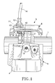
- Fig. 1 shows in a side view a bearing housing with a measurement device in accordance with the invention, wherein a part of the bearing housing outer wall has been cut out for increasing the clarity of the arrangement.
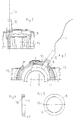
- Fig. 2 is a side view of the upper half of the bearing housing according to Fig. 1.
- Fig. 3 shows a front view of the upper half of the bearing housing according to Fig. 2, with a portion of the housing wall cut away around the position of a sensor fitted to the upper bearing housing half, according to Fig. 2.
- Fig. 4 and 5 show separately an element provided in the interior of the bearing housing in cross section and in a planar side view respectively.
- Fig. 1 shows a portion of a shaft 1 rotatably supported in a bearing 2, which is fitted in a seat in a bearing housing 3.
- the bearing housing is shown from an end face and has a base 4 made in on piece with a first, lower bearing housing half 5.
- this lower bearing housing half 5 has a pair of threaded through-holes 6, 7 intended for fitting of sensors used for vibration measuring purposes. These through-holes 6, 7 and their associated sensors have nothing to do with the present invention and therefor they will not be further discussed hereinafter.
- the bearing housing further incorporates a second, upper bearing housing half in the art referred to as a cap 8, which is shown with a portion cut away, for illustrating a part of the interior of the bearing housing.
- the bearing 2 is attached to the shaft I with aid of a lock nut 9 and a locking washer 10.
- the cap 8 is also provided with a threaded through-hole 11, in which is inserted a sensor 12, which has its free end 13 positioned at a short distance from the outer envelope surface of the lock nut 9.
- the sensor 12 is via a cable 14 connected to a not shown external evaluation unit, for establishing and detecting the rotational speed of the shaft, i.e. of the lock nut 9, which rotates together with the shaft 1.
- Fig. 2 shows in an end view the cap 8 and the positioning of the sensor 12 with its cable 14.
- a raised portion 15 which forms a seat for a not shown bolt for connecting the cap 8 to the first, lower bearing housing half or base.
- a portion of the lock nut 9 which is used in a conventional manner for arresting the bearing 2 (see Fig. 1) to the shaft 1.
- Such a lock nut 9 is shown more in detail in cross section in Fig. 4 and in a planar end view in Fig. 5, and it comprises a ring member having an internal thread 16 for connection to an external thread on the shaft 1, and by means of which the bearing can be clamped against a shoulder on the shaft or the like.
- the ring member is provided with a number of key grip recesses, in the embodiment shown four equidistantly positioned recesses 17 for permitting a hook spanner to be applied for tightening the lock nut 9 on a thread in the shaft or on a sleeve.
- the free end 13 of the sensor 12 is positioned in close proximity to the outer envelope surface of the lock nut 9, and with its longitudinal direction perpendicularly thereto.
- the spacing between the end surface of the sensor and the outer envelope surface of the lock nut is partly dependent on the type of sensor used, but distances up to about 2 mm are useful, although the best result is obtained if the distance is about 1 mm.
- the lock nut 9 When tightened the lock nut 9 is fixedly attached to the shaft 1, so that it will rotate at the same speed as the shaft, and for detecting this rotational speed is used an inductive sensor, for instance a sensor from Gerhard Balluff GmbH & Co, Neuhausen, Germany, available on the market under the name Balluff BES 516-325-E5-Y-S49.
- an inductive sensor for instance a sensor from Gerhard Balluff GmbH & Co, Neuhausen, Germany, available on the market under the name Balluff BES 516-325-E5-Y-S49.
- an inductive sensor of this type By using an inductive sensor of this type, positioned at a very short distance from the surface to be scanned the risk for disturbance in the metering result, caused by e.g. lubrication fat and the like is eliminated, when measuring against the metallic lock nut 9 and the evenly spaced recesses 17 therein.
- lock nuts of the type illustrated having four key grip recesses but it is of course also possible to use such lock nuts having eight, evenly spaced apart recesses, whereby the evaluation unit is programmed to count eight pulses for 360 degrees rotation.
- the component present in the bearing housing thus is a lock nut intended primarily for other mechanical purpose, i.e. arresting the bearing to the shaft, and the irregular surface portion functioning as the markings are the key grip recesses present in the outer envelope surface of the lock nut for allowing tightening thereof.
- the invention is not limited to such a component as a lock nut, but this could be substituted e.g. by a locking washer as illustrated at 10 in Fig. 1, and the irregular surface portion must not necessarily be recesses, but can instead be other surface irregularities, such as elevated portions or the like.
Landscapes
- Engineering & Computer Science (AREA)
- General Engineering & Computer Science (AREA)
- Mechanical Engineering (AREA)
- Physics & Mathematics (AREA)
- General Physics & Mathematics (AREA)
- Rolling Contact Bearings (AREA)
Abstract
A bearing housing (3) with a speed measurement device incorporating a sensor (12),
arranged to detect the rotational speed of a shaft (1) supported in a bearing (2) in the
bearing housing, said sensor being arranged to detect at least one marking rotating with
the shaft and having a cable (14) connected to an external evaluation unit, wherein the
marking is an irregular surface portion (17) of a component (9) present in the bearing
housing (3) for another mechanical purpose and rotating with the shaft (1).
Description
- The present invention refers to a bearing housing with a speed measurement device, in accordance with the preamble of the accompanying
claim 1. - In many different circumstances it can be of great interest to determine the rotational speed of a rotating shaft supported in bearings disposed in a bearing housing, i.a. for establishing sudden variations in said speed. For such purposes it has earlier been used different solutions incorporating e.g. making some sort of marking in the shaft itself, which marking then has been detected optically. However this method can give a questionable result, as fat contained in the bearing housing for lubricating purposes, occasionally may cover one or more of the markings, thereby giving improper readings.
- Furthermore it has been designed solutions utilising magnetic markings, which have been detected by sensors positioned in end covers of the bearing housing.
- These earlier used solutions require that the shaft is machined in some way or in another manner is provided with an additional marking, and besides being rather expensive they are not always particularly reliable, due to various reasons for disturbance.
- The purpose of the present invention is to provide a simple, inexpensive and reliable measurement device in a bearing housing, for metering the rotational speed of a shaft supported in at least one bearing in said bearing housing and particularly at low rotational speeds of up to e.g. 900 rpm. The purpose of the invention has been achieved with a bearing housing with a speed measurement device incorporating a sensor, arranged to detect the rotational speed of a shaft supported in a bearing in the bearing housing, said sensor being arranged to detect at least one marking rotating with the shaft and having a cable connected to an external evaluation unit, in the fact that the marking is an irregular surface portion of a component present in the bearing housing for another mechanical purpose and rotating with the shaft.
- Hereinafter, the invention will be further described and elucidated by way of a preferred, but non-limiting embodiment shown in the accompanying drawings.
- Fig. 1 shows in a side view a bearing housing with a measurement device in accordance with the invention, wherein a part of the bearing housing outer wall has been cut out for increasing the clarity of the arrangement.
- Fig. 2 is a side view of the upper half of the bearing housing according to Fig. 1.
- Fig. 3 shows a front view of the upper half of the bearing housing according to Fig. 2, with a portion of the housing wall cut away around the position of a sensor fitted to the upper bearing housing half, according to Fig. 2.
- Fig. 4 and 5 show separately an element provided in the interior of the bearing housing in cross section and in a planar side view respectively.
- Fig. 1 shows a portion of a
shaft 1 rotatably supported in abearing 2, which is fitted in a seat in abearing housing 3. The bearing housing is shown from an end face and has abase 4 made in on piece with a first, lower bearinghousing half 5. In the embodiment shown, this lower bearinghousing half 5 has a pair of threaded through-holes holes - The bearing housing further incorporates a second, upper bearing housing half in the art referred to as a
cap 8, which is shown with a portion cut away, for illustrating a part of the interior of the bearing housing. Thebearing 2 is attached to the shaft I with aid of alock nut 9 and alocking washer 10. Thecap 8 is also provided with a threaded through-hole 11, in which is inserted asensor 12, which has itsfree end 13 positioned at a short distance from the outer envelope surface of thelock nut 9. Thesensor 12 is via acable 14 connected to a not shown external evaluation unit, for establishing and detecting the rotational speed of the shaft, i.e. of thelock nut 9, which rotates together with theshaft 1. - Fig. 2 shows in an end view the
cap 8 and the positioning of thesensor 12 with itscable 14. In the centre of the end side of the housing is provided a raisedportion 15, which forms a seat for a not shown bolt for connecting thecap 8 to the first, lower bearing housing half or base. - In Fig. 3 the bearing
housing cap 8 according to Fig. 2 is shown in a front view, where a portion has been cut out in the region of thesensor 12 for better illustrating the interior of the bearing housing. At the cut out portion can be seen a portion of thelock nut 9, which is used in a conventional manner for arresting the bearing 2 (see Fig. 1) to theshaft 1. Such alock nut 9 is shown more in detail in cross section in Fig. 4 and in a planar end view in Fig. 5, and it comprises a ring member having aninternal thread 16 for connection to an external thread on theshaft 1, and by means of which the bearing can be clamped against a shoulder on the shaft or the like. Externally the ring member is provided with a number of key grip recesses, in the embodiment shown four equidistantly positionedrecesses 17 for permitting a hook spanner to be applied for tightening thelock nut 9 on a thread in the shaft or on a sleeve. - As seen in Fig. 3 the
free end 13 of thesensor 12 is positioned in close proximity to the outer envelope surface of thelock nut 9, and with its longitudinal direction perpendicularly thereto. The spacing between the end surface of the sensor and the outer envelope surface of the lock nut is partly dependent on the type of sensor used, but distances up to about 2 mm are useful, although the best result is obtained if the distance is about 1 mm. - When tightened the
lock nut 9 is fixedly attached to theshaft 1, so that it will rotate at the same speed as the shaft, and for detecting this rotational speed is used an inductive sensor, for instance a sensor from Gerhard Balluff GmbH & Co, Neuhausen, Germany, available on the market under the name Balluff BES 516-325-E5-Y-S49. - With this
sensor 12 positioned with itsfree end 13 at a distance of, preferably 1 mm from the outer envelope surface of thelock nut 9, the sensor will detect the passage of eachrecess 17 in thelock nut 9 as theserecesses 17 during the rotation move past thesensor 12. Each passage of a recess produces a pulse which via thecable 14 is transferred to the not shown external evaluation unit. In this manner each 360° revolution results in 4 pulses being transferred to the evaluation unit, and this unit therefore can establish in a simple manner the current rotational speed of the shaft, also at comparatively low speeds, e.g. between 50 rpm and 900 rpm. - By utilising the recesses present in a lock nut rotating with the shaft, and which lock nut primarily is intended for arresting the inner ring of the bearing to the shaft, it is possible in a very simple and convenient manner to pick up signals representative for the rotational speed with a standard sensor, without the necessity to provide the bearing or the shaft with any especial markings of the type referred to in the introductory part of the specification.
- By using an inductive sensor of this type, positioned at a very short distance from the surface to be scanned the risk for disturbance in the metering result, caused by e.g. lubrication fat and the like is eliminated, when measuring against the
metallic lock nut 9 and the evenlyspaced recesses 17 therein. - Of course it is not necessary to use lock nuts of the type illustrated, having four key grip recesses but it is of course also possible to use such lock nuts having eight, evenly spaced apart recesses, whereby the evaluation unit is programmed to count eight pulses for 360 degrees rotation.
- By utilising a component - i.e. the lock nut for arresting the bearing - which is already present in the bearing housing, the only additional thing needed is to provide a threaded hole for the sensor.
- In the embodiment of the invention shown in the drawings and described in connection thereto, the component present in the bearing housing, thus is a lock nut intended primarily for other mechanical purpose, i.e. arresting the bearing to the shaft, and the irregular surface portion functioning as the markings are the key grip recesses present in the outer envelope surface of the lock nut for allowing tightening thereof.
- However the invention is not limited to such a component as a lock nut, but this could be substituted e.g. by a locking washer as illustrated at 10 in Fig. 1, and the irregular surface portion must not necessarily be recesses, but can instead be other surface irregularities, such as elevated portions or the like.
Claims (5)
- A bearing housing (3) with a speed measurement device incorporating a sensor (12), arranged to detect the rotational speed of a shaft (1) supported in a bearing (2) in the bearing housing, said sensor being arranged to detect at least one marking rotating with the shaft and having a cable (14) connected to an external evaluation unit,
characterized therein,
that the marking is an irregular surface portion (17) of a component (9) present in the bearing housing (3) and primarily intended for another mechanical purpose and rotating with the shaft (1). - A device as claimed in claim 1,
characterized therein,
that the sensor (12) is an inductive sensor, whereas the component (9) having the marking is of a metallic material. - A device as claimed in claim 1 or 2,
characterized therein,
that the component (9) having the marking is a lock nut (9) for arresting the bearing (2) to the shaft, and the at least one marking is key grip recesses (17) evenly distributed around the outer circumference of the lock nut outer envelope surface. - A device as claimed in anyone of the preceeding claims,
characterized therein,
that a free end (13) of the sensor (12) is positioned at a short distance from the outer envelope surface of the component (9) and with the longitudinal direction of the sensor perpendicular to the outer envelope surface of the component (9). - A device as claimed in claim 4,
characterized therein,
that the distance between the component (9) and the free end (13) of the sensor (12) is up to 2 mm, and preferably about 1 mm.
Applications Claiming Priority (2)
| Application Number | Priority Date | Filing Date | Title |
|---|---|---|---|
| SE0003483A SE0003483L (en) | 2000-09-28 | 2000-09-28 | Warehouse with speed measuring device |
| SE0003483 | 2000-09-28 |
Publications (1)
| Publication Number | Publication Date |
|---|---|
| EP1193500A2 true EP1193500A2 (en) | 2002-04-03 |
Family
ID=20281206
Family Applications (1)
| Application Number | Title | Priority Date | Filing Date |
|---|---|---|---|
| EP01850164A Withdrawn EP1193500A2 (en) | 2000-09-28 | 2001-09-21 | Bearing housing with speed measurement device |
Country Status (5)
| Country | Link |
|---|---|
| US (1) | US20020036494A1 (en) |
| EP (1) | EP1193500A2 (en) |
| JP (1) | JP2002181059A (en) |
| CN (1) | CN1344935A (en) |
| SE (1) | SE0003483L (en) |
Cited By (1)
| Publication number | Priority date | Publication date | Assignee | Title |
|---|---|---|---|---|
| EP2644921A1 (en) * | 2012-03-28 | 2013-10-02 | Schaeffler Technologies AG & Co. KG | Rolling bearing assembly with sensor and encoder attached to the rotatable ring of a rolling bearing incorporated in a bearing housing |
-
2000
- 2000-09-28 SE SE0003483A patent/SE0003483L/en not_active Application Discontinuation
-
2001
- 2001-09-21 EP EP01850164A patent/EP1193500A2/en not_active Withdrawn
- 2001-09-28 CN CN01141222A patent/CN1344935A/en active Pending
- 2001-09-28 JP JP2001302169A patent/JP2002181059A/en active Pending
- 2001-09-28 US US09/964,446 patent/US20020036494A1/en not_active Abandoned
Cited By (1)
| Publication number | Priority date | Publication date | Assignee | Title |
|---|---|---|---|---|
| EP2644921A1 (en) * | 2012-03-28 | 2013-10-02 | Schaeffler Technologies AG & Co. KG | Rolling bearing assembly with sensor and encoder attached to the rotatable ring of a rolling bearing incorporated in a bearing housing |
Also Published As
| Publication number | Publication date |
|---|---|
| JP2002181059A (en) | 2002-06-26 |
| SE0003483L (en) | 2002-03-29 |
| US20020036494A1 (en) | 2002-03-28 |
| CN1344935A (en) | 2002-04-17 |
| SE0003483D0 (en) | 2000-09-28 |
Similar Documents
| Publication | Publication Date | Title |
|---|---|---|
| US4864231A (en) | Bearing assembly having a wheel speed sensor | |
| US5198763A (en) | Apparatus for monitoring the axial and radial wear on a bearing of a rotary shaft | |
| EP0250275B1 (en) | Bearing with sensor | |
| EP0443514B1 (en) | Apparatus for monitoring a bearing | |
| US5336996A (en) | Hall effect monitoring of wear of bearing supporting a rotor within a stationary housing | |
| CA2380280A1 (en) | Shaft voltage and current monitoring system | |
| FR2962761B1 (en) | FLUID FLOW SENSOR | |
| FR2661246A1 (en) | DEVICE FOR MEASURING A TORQUE ON A TREE. | |
| JPH01140070A (en) | Roller bearing having pulse ring for measurement of revolutions | |
| EP0817972B1 (en) | Bearing assembly having integrated speed sensor | |
| EP0840884B1 (en) | Dynamometric detector device and method for bearings | |
| CN106167046B (en) | Sensor module for the rotational angle for obtaining the rotating member in vehicle | |
| EP1258642B1 (en) | Bearing housing with measurement device | |
| US7265537B2 (en) | Annular sensor housing | |
| US6905393B2 (en) | Method for simultaneous machining and measuring parameters of a surface being subjected to machining | |
| US7282907B2 (en) | Antifriction bearing unit having a sensor and a resolver | |
| US20030051549A1 (en) | Bearing assembly with integral sensor for sensing rotation | |
| US20020036494A1 (en) | Bearing housing with speed measurement device | |
| KR950014942B1 (en) | Device for measuring rotational parameters of the axis of rotation | |
| JPH08254402A (en) | Rotation axis monitoring device | |
| JP3256726B2 (en) | Container with mechanical seal with monitoring | |
| JP2548059Y2 (en) | Rotation detection device | |
| KR20030070844A (en) | Press-in exciter ring assembly | |
| JP3725502B2 (en) | Magnet coupling rotation inspection device | |
| JP2020061852A (en) | Gear for rotation detection, rotation detector and electric motor |
Legal Events
| Date | Code | Title | Description |
|---|---|---|---|
| PUAI | Public reference made under article 153(3) epc to a published international application that has entered the european phase |
Free format text: ORIGINAL CODE: 0009012 |
|
| AK | Designated contracting states |
Kind code of ref document: A2 Designated state(s): AT BE CH CY DE DK ES FI FR GB GR IE IT LI LU MC NL PT SE TR |
|
| AX | Request for extension of the european patent |
Free format text: AL;LT;LV;MK;RO;SI |
|
| STAA | Information on the status of an ep patent application or granted ep patent |
Free format text: STATUS: THE APPLICATION HAS BEEN WITHDRAWN |
|
| 18W | Application withdrawn |
Withdrawal date: 20020528 |