EP1193496A1 - Branch pipe device for gradient high performance liquid chromatography - Google Patents
Branch pipe device for gradient high performance liquid chromatography Download PDFInfo
- Publication number
- EP1193496A1 EP1193496A1 EP00925641A EP00925641A EP1193496A1 EP 1193496 A1 EP1193496 A1 EP 1193496A1 EP 00925641 A EP00925641 A EP 00925641A EP 00925641 A EP00925641 A EP 00925641A EP 1193496 A1 EP1193496 A1 EP 1193496A1
- Authority
- EP
- European Patent Office
- Prior art keywords
- splitted
- high performance
- performance liquid
- liquid chromatography
- tubing
- Prior art date
- Legal status (The legal status is an assumption and is not a legal conclusion. Google has not performed a legal analysis and makes no representation as to the accuracy of the status listed.)
- Withdrawn
Links
Images


Classifications
-
- B—PERFORMING OPERATIONS; TRANSPORTING
- B01—PHYSICAL OR CHEMICAL PROCESSES OR APPARATUS IN GENERAL
- B01F—MIXING, e.g. DISSOLVING, EMULSIFYING OR DISPERSING
- B01F25/00—Flow mixers; Mixers for falling materials, e.g. solid particles
- B01F25/40—Static mixers
- B01F25/42—Static mixers in which the mixing is affected by moving the components jointly in changing directions, e.g. in tubes provided with baffles or obstructions
- B01F25/43—Mixing tubes, e.g. wherein the material is moved in a radial or partly reversed direction
- B01F25/432—Mixing tubes, e.g. wherein the material is moved in a radial or partly reversed direction with means for dividing the material flow into separate sub-flows and for repositioning and recombining these sub-flows; Cross-mixing, e.g. conducting the outer layer of the material nearer to the axis of the tube or vice-versa
-
- G—PHYSICS
- G01—MEASURING; TESTING
- G01N—INVESTIGATING OR ANALYSING MATERIALS BY DETERMINING THEIR CHEMICAL OR PHYSICAL PROPERTIES
- G01N30/00—Investigating or analysing materials by separation into components using adsorption, absorption or similar phenomena or using ion-exchange, e.g. chromatography or field flow fractionation
- G01N30/02—Column chromatography
- G01N30/26—Conditioning of the fluid carrier; Flow patterns
- G01N30/28—Control of physical parameters of the fluid carrier
- G01N30/34—Control of physical parameters of the fluid carrier of fluid composition, e.g. gradient
-
- G—PHYSICS
- G01—MEASURING; TESTING
- G01N—INVESTIGATING OR ANALYSING MATERIALS BY DETERMINING THEIR CHEMICAL OR PHYSICAL PROPERTIES
- G01N30/00—Investigating or analysing materials by separation into components using adsorption, absorption or similar phenomena or using ion-exchange, e.g. chromatography or field flow fractionation
- G01N30/02—Column chromatography
- G01N30/26—Conditioning of the fluid carrier; Flow patterns
- G01N30/28—Control of physical parameters of the fluid carrier
- G01N30/34—Control of physical parameters of the fluid carrier of fluid composition, e.g. gradient
- G01N2030/347—Control of physical parameters of the fluid carrier of fluid composition, e.g. gradient mixers
-
- G—PHYSICS
- G01—MEASURING; TESTING
- G01N—INVESTIGATING OR ANALYSING MATERIALS BY DETERMINING THEIR CHEMICAL OR PHYSICAL PROPERTIES
- G01N30/00—Investigating or analysing materials by separation into components using adsorption, absorption or similar phenomena or using ion-exchange, e.g. chromatography or field flow fractionation
- G01N30/02—Column chromatography
- G01N30/60—Construction of the column
- G01N30/6095—Micromachined or nanomachined, e.g. micro- or nanosize
Definitions
- the present invention relates to a gradient high performance liquid chromatography using a splitted tubing apparatus in which in order to achieve gradient elution, a mobile phase supplied by a pump is splitted into plural passages so as to be joined again thereafter.
- a low flow high performance liquid chromatography (HPLC) using a micro column having an inner diameter of less than 0.1 mm, a semi-micro column or a capillary column is suitable for high-sensitive analysis of trace components, and in particular an HPLC/ESI-MS system connected online to an electro-spray ionization mass spectrometer (ESI-MS) is widely used in various fields.
- HPLC/ESI-MS system connected online to an electro-spray ionization mass spectrometer (ESI-MS) is widely used in various fields.
- the present invention provides a splitted tubing apparatus which comprises a solvent inlet part, a splitted tubing part splitted into plural two or more tubes, and a solvent outlet part for a gradient high performance chromatography.
- the present invention also provides a gradient high performance chromatography including a splitted tubing apparatus comprising a solvent inlet part, a splitted tubing part splitted into plural two or more tubes; and a solvent outlet part.
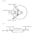
- the present invention also provides a splitted tubing apparatus for a gradient high performance chromatography, in which, as shown in Fig. 1, a tube of a solvent inlet part and tubes of a splitted tubing part splitted into plural two or more tubes are connected together via a connector (X), and the tubes of the splitted tubing part and a tube of a solvent outlet part are connected together via a connector (Y). That is, a mobile phase supplied by a pump (P) is splitted into plural passages at the connector (X) so as to join again thereafter at the connector (Y).
- the present invention also provides an analyzing method of trace components in a sample, in which after a mobile phase is fed to the splitted tubing apparatus by a pump (P) so as to sequentially fill the solvent inlet part, the splitted tubing part splitted into plural two or more tubes, and the solvent outlet part, a target component is eluted from a separation column according to an arbitrary gradient-elution linear line or curve by feeding a mobile phase with a different composition.
- P a pump
- the splitted tubing apparatus is used by connecting to the pump (P) via a tube.
- the splitted tubing part of the splitted tubing apparatus between the solvent inlet part and the solvent outlet part is formed of plural tubes, which are the same or different in length and/or inner diameter, arranged in parallel, enabling an arbitrary gradient-elution pattern to be readily performed.
- plural tubes having the same inner diameter and only different lengths may be arranged in parallel; plural tubes having the same length and only different inner diameters may be arranged in parallel; or plural tubes having different both inner diameters and lengths may be arranged in parallel.
- each inner diameter of splitted tubes arranged in parallel may vary at an intermediate portion of the tube; or a new connector may be arranged at an intermediate portion of each splitted tube so that tubes across the connector may have different inner diameters so as to be connected together.
- the lengths of plural splitted tubes of the splitted tubing apparatus between the solvent inlet part and the solvent outlet part are not limited, and the inner diameters of the tubes may be changed from several micrometers to 1 mm or from 1 ⁇ m to 1 mm.
- Each material of the splitted tubes and the connectors may be stainless steel, glass, or a synthetic resin, for example; however, it is not specifically limited.
- the synthetic resin there may be polyether ether ketone (PEEK) and Teflon, for example.
- the number of the plural splitted tubes i.e., the number of splits at the passage of the connector (X) shown in Fig. 1, may be not limited as long as it is 2 or more; with increasing the number of more than three splits, a finer gradient elution pattern can be readily established.
- the mobile phase has a step-gradient mobile-phase system when passing through the solvent outlet part of the splitted tubing apparatus.
- the present invention also provides a splitted tubing apparatus for a gradient high performance liquid chromatography, in which a mobile phase eluted from the tube of the solvent outlet part of the splitted tubing apparatus is allowed to flow into the solvent mixing device.
- the solvent mixing device is connected to the splitted tubing apparatus shown in Fig. 1, so that a mobile phase supplied from the pump (P) is allowed to sequentially pass through the splitted tubing apparatus and the solvent mixing device in that order.
- a mobile phase having a step-gradient mobile-phase composition can be obtained; thereafter, by allowing to pass through the solvent mixing device, by which alone, a gradient composition with an exponentially functional curve could be obtained, a linear line gradient (linear gradient) or linear-gradient like arbitrary gradient elution pattern can be obtained by superimposing both the different gradient compositions.
- the solvent mixing device there may be a chamber device in which agitation and mixing are performed with an agitator and the like or an available mixing connector device; however, it is not of course limited to those and a device of any structure may be used as long as it can efficiently mix the mobile phase solvents fed thereto.
- the present invention provides a splitted tubing apparatus for a gradient high-performance liquid chromatography, in which the connector (Y) has a function for mixing solvents. That is, in the splitted tubing apparatus with the connector (Y) having a function for mixing solvents, by allowing a mobile phase supplied from the pump (P) to pass through the splitted tubing apparatus, a linear gradient or linear-gradient like arbitrary gradient elution pattern can be obtained.
- the solvent outlet part of the splitted tubing apparatus need not to be connected to a different solvent mixing device.
- a mixing connector device and/or a connector (Y) having a function for mixing solvents to which splitted tubes in the splitted tubing apparatus are joined are required to have a sufficient mixing function of mobile phases.
- a mixer capacity inside the connector (dead volume) is increased sufficient enough relative to the velocity of the mobile phase; 2) a mixer inside the connector is made to have a shape suitable for mixing the solvent-flow; and 3) a frit (film) is formed, for example.
- a mixer capacity inside the connector dead volume
- a mixer inside the connector is made to have a shape suitable for mixing the solvent-flow
- 3) a frit (film) is formed, for example.
- the mixer internal capacity (dead volume) of the solvent mixing device or the connector (Y) having a function for mixing solvents in the splitted tubing be from 2 to 1000 relative to 1 for the velocity of the mobile phase (the moving volume per minute of the mobile phase).
- the frit (film) in the solvent mixing device or the connector (Y) there may be a sintered filter, ceramics, metallic mesh, or cellulose fiber, for example; however, it is of course not limited to these.
- the splitted tubing apparatus for a gradient high performance liquid chromatography can be widely used for from a normal gradient high performance liquid chromatography used at a flow rate of several milli-liters per minute, i.e., from 0.1 to 3 ml/m, for example, to a low flow gradient high performance liquid chromatography used at an extremely low speed.
- a normal gradient high performance liquid chromatography used at a flow rate of several milli-liters per minute, i.e., from 0.1 to 3 ml/m, for example, to a low flow gradient high performance liquid chromatography used at an extremely low speed.
- the usefulness of the splitted tubing apparatus according to the present invention is much more displayed; however, it is of course not limited to this.
- the low flow gradient high performance liquid chromatography there may be: a gradient micro high performance liquid chromatography having a micro-column with an inner diameter of 0.5 to 1 mm and used at a flow rate of several tens micro-litters per minute, i.e., from 10 to 90 ⁇ L/m, for example; a gradient semi-micro high performance liquid chromatography having a semi-micro-column with an inner diameter of 1 to 2.5 mm and used at a flow rate of 50 to 250 ⁇ L/m; or a gradient capillary high performance liquid chromatography having a capillary column with an inner diameter of less than 0.5 mm and used at a flow rate of less than several micro-litters per minute, i.e., less than 10 ⁇ L/m normally.
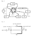
- the present invention provides a low flow gradient high performance chromatography in which a pump (P1), an injector (I), a switching valve (V), a column for concentrating components (M), the switching valve (V), a solvent mixing device (MC), a splitted tubing apparatus (ST), and the switching valve (V) are connected in that order, and along another line, a pump (P2), the switching valve (V), the splitted tubing apparatus (ST), the solvent mixing device (MC), the switching valve (V), the column for concentrating components (M), the switching valve (V), a separating column (C), and a detector (D) are connected in that order, as shown in Fig. 2.
- the present invention also provides an analyzing method of trace components in a sample in that in the above described low flow gradient high performance liquid chromatography, from a mobile phase supplied by the pump (P1), a target component is acquired in the column for concentrating components (M); then, by switching the switching valve (V), the mobile phase is fed to the splitted tubing apparatus (ST) and the solvent mixing device (MC) in that order by the pump (P2), so that a mobile phase with a linear gradient or linear-gradient like arbitrary composition is formulated so as to allow the target component to be gradient-eluted from the separating column (C).
- the present invention provides a low flow gradient high performance chromatography in which a pump (P1), an injector (I), a switching valve (V), a column for concentrating components (M), the switching valve (V), a splitted tubing apparatus having a function for mixing solvents (STM), and the switching valve (V) are connected together in that order, and along another line, a pump (P2), the switching valve (V), the splitted tubing apparatus having a function for mixing solvents (STM), the switching valve (V), the column for concentrating components (M), the switching valve (V), a separating column (C), and a detector (D) are connected together in that order, as shown in Fig. 3.
- a pump (P1), an injector (I), a switching valve (V), a column for concentrating components (M), the switching valve (V), a splitted tubing apparatus having a function for mixing solvents (STM), and the switching valve (V) are connected together in that order, and along another line, a pump (P2),
- the present invention also provides an analyzing method of trace components in samples in that in the above described low flow gradient high performance liquid chromatography, from a mobile phase supplied by the pump (P1), a target component is acquired in the column for concentrating components (M); then, by switching the switching valve (V), the mobile phase is fed to the splitted tubing apparatus having a function for mixing solvents (STM) by a pump (P2), so that a mobile phase with a linear gradient or linear-gradient like arbitrary composition is formed so as to allow the target component to be gradient-eluted from the separating column (C).
- STM mixing solvents
- Arranging a splitted tubing apparatus according to the present invention in a gradient high performance liquid chromatography formed as follows results in a system capable of analyzing trace components at a high-speed and high-sensitivity according to an arbitrary gradient straight line or curve.
- Fig. 1 shows a splitted tubing apparatus according to the present invention
- Figs. 2 and 3 are schematic representations of samples of a low flow gradient high performance liquid chromatography including the splitted tubing apparatus; the present invention is not certainly limited to these. The system will be described in detail with reference to Figs. 1 to 3.
- Fig. 1 is a drawing of a splitted tubing apparatus for a gradient high performance liquid chromatography according to the present invention, which comprises a tube of a solvent inlet part at one of both ends and a tube of a solvent outlet part at the other end, wherein the tube between the tube of the solvent inlet part and the tube of the solvent outlet part is splitted into two or more plural tubes.
- a mobile phase supplied by a liquid (P) enters into the apparatus from a solvent inlet part at one end so as to join again at a connector (Y) after being divided into plural tubes at a connector (X), so that the mobile phase flows out of the tube of the solvent outlet part at the other end.
- a mobile phase with another composition is fed so that a target component can be eluted according to an arbitrary gradient elution straight line or curve from a separating column.
- the flow velocity in the solvent inlet part is divided after a mobile phase passes through the connector (X) according to the resistance of each of splitted tubes, so that the mobile phase in each of plural splitted tubes connected to the connector (X) moves at a different flow-velocity in the splitted tube.
- the resistance of each of plural splitted tubes depends on the length and/or inner diameter of the tube
- the flow velocity in each of the splitted tubes can be changed by changing the length and/or inner diameter of the splitted tube so as to produce shifts in time at which the mobile phase approaches the connector (Y) to join.
- An apparatus creating an arbitrary gradient pattern by utilizing the shift in time for approaching the connector (Y) via each splitted tube is a splitted tubing apparatus according to the present invention.
- the splitted tubing apparatus shown in Fig. 1 is used by connecting the tube of the solvent inlet to the pump and the tube of the solvent outlet to the separating column. Also, during linear gradient or linear-gradient like arbitrary eluting, the splitted tubing apparatus shown in Fig. 1 is used by connecting the tube of the solvent inlet to the pump and the tube of the solvent outlet is connected to the separating column after connecting to the solvent mixing device.
- the connector (Y) to which plural splitted tubes in the splitted tubing apparatus shown in Fig.
- the splitted tubing apparatus is not required to connect to the solvent mixing device, wherein by connecting the tube of the solvent inlet in the splitted tubing apparatus shown in Fig. 1 to the pump and the tube of the solvent outlet to the separating column, a mobile phase with a linear gradient or linear-gradient like arbitrary composition can be formed.
- Arranging a splitted tubing apparatus according to the present invention in a low flow gradient high performance liquid chromatography formed as follows results in forming a mobile phase with a linear gradient or linear gradient-like arbitrary composition. Therefore, the system becomes to be suitable for an analysis of trace components at high speed and high sensitivity.
- Fig. 2 is a schematic view of a low flow gradient high performance liquid chromatography, in which a pump (P1), an injector (I), a switching valve (V), a column for concentrating components (M), the switching valve (V), a solvent mixing device (MC), a splitted tubing apparatus (ST), and the switching valve (V) are connected together in that order, and along another line, a pump (P2), the switching valve (V), the splitted tubing apparatus (ST), the solvent mixing device (MC), the switching valve (V), the column for concentrating components (M), the switching valve (V), a separating column (C), and a detector (D) are connected together in that order.
- a method for concentrating and separating components in the low flow gradient high performance liquid chromatography is described as follows.
- the separation and analysis of the trace target component with high sensitivity can be achieved; this is one of the features of the present invention.
- this system can be combined with various functional films as the column for concentrating components (M) in order to concentrate the target component, so that the wide applicability is also one of the features.
- the pump there may be a syringe pump and a pump with a plunger, for example; it may be preferably a pump for low flow gradient high performance liquid chromatography.
- the valve there may be a ten-way and a six-way valve for a high performance liquid chromatography.
- the injector is a device for injecting sample solution into the high performance liquid chromatography; the separating column is a column for separating the target component in the sample, in which a so-called normal-phase column, a reversed-phase column, and so forth may be selected according to the object.
- these devices commercially available products may be used.
- FIG. 3 is a schematic view of a low flow gradient high performance liquid chromatography, in which the pump (P1), the injector (I), the switching valve (V), the column for concentrating components (M), the switching valve (V), the splitted tubing apparatus having a function for mixing solvents (STM), and the switching valve (V) are connected together in that order, and along another line, the pump (P2), the switching valve (V), the splitted tubing apparatus having a function for mixing solyents (STM), the switching valve (V), the column for concentrating components (M), the switching valve (V), the separating column (C), and the detector (D) are connected together in that order.
- the pump (P1), the injector (I), the switching valve (V), the column for concentrating components (M), the switching valve (V), the splitted tubing apparatus having a function for mixing solvents (STM), and the switching valve (V) are connected together in that order, and along another line, the pump (P2), the switching valve (V), the splitted tub
- a target trace component can be separated and analyzed with high sensitivity according to the present invention.
- the gradient-elution was performed by the method below so as to investigate the effect of the splitted tubing apparatus (ST) having the solvent mixing device (a chamber capacity of 120 mL) connected thereto on a gradient elution pattern.
- the gradient elution was evaluated in a state that the column for concentrating components (M) and the separating column (C) were not arranged to the low flow gradient high performance liquid chromatography in that order to enable to evaluate the effect of the splitted tubing apparatus easily.
- distilled water for HPLC was fed as A liquid at a flow rate of 20 mL/min by the pump (P1) so as to fill the entire system with the distilled water for HPLC in a sequence of the injector (I), the switching valve (V), the solvent mixing device (MC), and the splitted tubing apparatus (ST) shown in Fig. 4.
- 3% acetone water solution was fed as B liquid at a flow rate of 20 mL/min by the pump (P2) so as to allow to flow through the splitted tubing apparatus (ST) shown in Fig. 4 and the solvent mixing device (MC) in that order, so that changes in the absorbance with a lapse of time at a wavelength of 254 nm were evaluated by the detector (D).
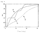
- Fig. 9 shows changes in the B liquid consistency obtained from the result of the changes in the absorbance with time after feeding the B liquid.
- the evaluations were also performed in the case 1) of not having the solvent mixing device (MC) attached thereto (having the splitted tubing apparatus (ST) attached thereto), and in the case 2) of not having the splitted tubing apparatus (ST) (having the solvent mixing device (MC) attached thereto).
- the initial flow-rate in the solvent inlet part was divided into each mobile phase flow-rate in each tube splitted into three tubes at the connector (X) substantially at a ratio of 1:1:1 after the mobile phase passed through the connector (X). Therefore, it is apparent that the split ratio can be controlled by the ratio of the plural splitted tubes in the splitted tubing apparatus in the length and/or inner diameter.
Landscapes
- Chemical & Material Sciences (AREA)
- General Health & Medical Sciences (AREA)
- Life Sciences & Earth Sciences (AREA)
- Health & Medical Sciences (AREA)
- Analytical Chemistry (AREA)
- Biochemistry (AREA)
- Physics & Mathematics (AREA)
- General Physics & Mathematics (AREA)
- Immunology (AREA)
- Pathology (AREA)
- Dispersion Chemistry (AREA)
- Chemical Kinetics & Catalysis (AREA)
- Treatment Of Liquids With Adsorbents In General (AREA)
- Sampling And Sample Adjustment (AREA)
Abstract
Description
Claims (21)
- A splitted tubing apparatus for a gradient high performance liquid chromatography, which comprises:a solvent inlet part;a splitted tubing part splitted into a plurality of two or more tubes; anda solvent outlet part.
- The splitted tubing apparatus for a gradient high performance liquid chromatography according to Claim 1, which further comprises:wherein tubes are connected together between the solvent inlet part and the splitted tubing part splitted into a plurality of two or more tubes via the connector and between the splitted tubing part and the solvent outlet part via the connector (X) and (Y), respectively, as shown in Fig. 1.a connector (X); anda connector (Y),
- The splitted tubing apparatus for a gradient high performance liquid chromatography according to Claim 1 or 2, which comprises a plurality of tubes each having the same or different length and/or internal diameter.
- The splitted tubing apparatus for a gradient high performance liquid chromatography according to any of Claims 1 to 3, wherein a mobile phase discharged from the tube of the solvent outlet part is allowed to flow in a solvent mixing device.
- The splitted tubing apparatus for a gradient high performance liquid chromatography according to Claim 2, wherein the connector (Y) joined with the plurality of splitted tubes as shown in Fig. 1, has a function for sufficiently mixing the solvents.
- The splitted tubing apparatus for a gradient high performance liquid chromatography according to any of Claims 1 to 5, wherein the gradient high performance liquid chromatography is a low flow gradient high performance liquid chromatography.
- The splitted tubing apparatus for a low flow gradient high performance liquid chromatography according to Claim 6, wherein the low flow gradient high performance liquid chromatography is a micro gradient high performance liquid chromatography, a semi-micro gradient high performance liquid chromatography or a capillary gradient high performance liquid chromatography.
- A method of analyzing trace components in a sample, which comprises the steps of:feeding a mobile phase into the splitted tubing apparatus according to any of Claims 1 to 7 by a pump (P);sequentially filling the solvent inlet part, the splitted tubing part splitted into a plurality of two or more tubes, and the solvent outlet part with the mobile phase; andeluting a target component from a separation column according to an arbitrary gradient-elution linear line or curve by feeding a mobile phase with a different composition.
- A low flow gradient high performance liquid chromatography in which, as shown in Fig. 2, a pump (P1), an injector (I), a switching valve (V), a column for concentrating components (M), the switching valve (V), a solvent mixing device (MC), the splitted tubing apparatus (ST) according to Claim 4, and the switching valve (V) are connected together in that order, and along another line, a pump (P2), the switching valve (V), the splitted tubing apparatus (ST) according to Claim 4, the solvent mixing device(MC), the switching valve (V), the column for concentrating components (M), the switching valve (V), a separating column (C), and a detector (D) are connected together in that order.
- An analytical method of trace components in a sample in the low flow gradient high performance liquid chromatography according to Claim 9, the method comprising the steps of:wherein the target component is eluted from the separating column (C) according to an arbitrary gradient-elution linear line or curve.capturing a target component within the column for concentrating components (M) from a mobile phase supplied by the pump (P1);switching the switching valve (V); andfeeding a mobile phase to the splitted tubing apparatus (ST) and the solvent mixing device (MC) in that order by the pump (P2),
- A low flow gradient high performance liquid chromatography in which, a pump (P1), an injector (I), a switching valve (V), a column for concentrating components (M), the switching valve (V), the splitted tubing apparatus (STM) according to Claim 5 and the switching valve (V) are connected together in that order, and along another line, a pump (P2), the switching valve (V), the splitted tubing apparatus (STM) according to Claim 5, the switching valve (V), the column for concentrating components (M), the switching valve (V), a separating column (C), and a detector (D) are connected together in that order, as shown in Fig. 3.
- An analytical method of trace components in a sample in the low flow gradient high performance liquid chromatography according to Claim 11, which comprises the steps of:wherein the target component is eluted from the separating column (C) according to an arbitrary gradient-elution linear line or curve.capturing a target component within the column for concentrating components (M) from a mobile phase supplied by the pump (P1);switching the switching valve (V); andfeeding a mobile phase to the splitted tubing apparatus (STM) according to Claim 5 by the pump (P2),
- A gradient high performance liquid chromatography comprising a splitted tubing apparatus, the apparatus comprising:a solvent inlet part;a splitted tubing part splitted into a plurality of two or more tubes; anda solvent outlet part.
- The chromatography according to Claim 13, wherein the splitted tubing apparatus further comprises:wherein a tube of the solvent inlet part and tubes of the splitted tubing part splitted into a plurality of two or more tubes are connected together via the connector (X), and the tubes of the splitted tubing part and a tube of the solvent outlet part are connected together via the connector (Y), as shown in Fig. 1.a connector (X); anda connector (Y),
- The chromatography according to Claim 13, wherein the splitted tubing apparatus comprises a plurality of tubes, each having the same or different length and/or internal diameter.
- The chromatography according to Claim 13, wherein a mobile phase pumped from a tube of the solvent outlet part of the splitted tubing apparatus is allowed to flow into a solvent mixing device.
- The chromatography according to Claim 14, wherein the connector (Y) which is joined with the plurality of splitted tubes as shown in Fig. 1, has a function for sufficiently mixing solvents.
- The chromatography according to Claim 13, wherein the gradient high performance liquid chromatography is a low flow gradient high performance liquid chromatography.
- The chromatography according to Claim 13, wherein the low flow gradient high performance liquid chromatography is a micro gradient high performance liquid chromatography, a semi-micro gradient high performance liquid chromatography or a capillary gradient high performance liquid chromatography.
- The chromatography according to Claim 18, wherein a pump (P1), an injector (I), a switching valve (V), a column for concentrating components (M), the switching valve (V), a solvent mixing device (MC), the splitted tubing apparatus (ST) comprising the solvent inlet part, the splitted tubing part splitted into a plurality of two or more tubes, and the solvent outlet part; and the switching valve (V) are connected together in that order so that a mobile phase discharged from a tube of the solvent outlet part of the splitted tubing apparatus is allowed to flow into the solvent mixing device, and along another line, a pump (P2), the switching valve (V), the abvoe-mentioned splitted tubing apparatus (ST), the solvent mixing device(MC), the switching valve (V), the column for concentrating components (M), the switching valve (V), a separating column (C), and a detector (D) are connected together in that order, as shown in Fig. 2.
- The chromatography according to Claim 18, wherein a pump (P1), an injector (I), a switching valve (V), a column for concentrating components (M), the switching valve (V), a splitted tubing apparatus (STM) in which tubes are connected together between the solvent inlet part and the splitted tubing part splitted into a plurality of two or more tubes and between the splitted tubing part and the solvent outlet part via a connector (x) and a connector (Y), respectively; and the switching valve (V) are connected together in that order, so that the connector (Y), which is joined with the plurality of splitted tubes as shown in Fig. 1, has a function for sufficiently mixing solvents, and along another line, a pump (P2), the switching valve (V), the splitted tubing apparatus (STM), the switching valve (V), the column for concentrating components (M), the switching valve (V), a separating column (C), and a detector (D) are connected together, as shown in Fig. 3.
Applications Claiming Priority (3)
| Application Number | Priority Date | Filing Date | Title |
|---|---|---|---|
| JP13885499 | 1999-05-19 | ||
| JP13885499 | 1999-05-19 | ||
| PCT/JP2000/003057 WO2000072001A1 (en) | 1999-05-19 | 2000-05-12 | Branch pipe device for gradient high performance liquid chromatography |
Publications (2)
| Publication Number | Publication Date |
|---|---|
| EP1193496A1 true EP1193496A1 (en) | 2002-04-03 |
| EP1193496A4 EP1193496A4 (en) | 2007-04-18 |
Family
ID=15231716
Family Applications (1)
| Application Number | Title | Priority Date | Filing Date |
|---|---|---|---|
| EP00925641A Withdrawn EP1193496A4 (en) | 1999-05-19 | 2000-05-12 | Branch pipe device for gradient high performance liquid chromatography |
Country Status (4)
| Country | Link |
|---|---|
| US (1) | US6581442B1 (en) |
| EP (1) | EP1193496A4 (en) |
| JP (1) | JP4043718B2 (en) |
| WO (1) | WO2000072001A1 (en) |
Cited By (7)
| Publication number | Priority date | Publication date | Assignee | Title |
|---|---|---|---|---|
| EP1416270A1 (en) * | 2002-11-04 | 2004-05-06 | General Electric Company | Systems and methods for spraying and optimization of solid oxide fuel cell materials |
| EP1408330A4 (en) * | 2001-06-07 | 2004-08-18 | Nano Solution Inc | LIQUID CHROMATOGRAPHER AND ANALYSIS SYSTEM |
| WO2013090141A1 (en) | 2011-12-14 | 2013-06-20 | Waters Technologies Corporation | Targeted frequency multiple path length mixers |
| PL423281A1 (en) * | 2017-10-26 | 2019-05-06 | Univ Jana Kochanowskiego W Kielcach | Three-position, six-way metering valve, preferably for the inverse gas chromatography |
| US11185830B2 (en) | 2017-09-06 | 2021-11-30 | Waters Technologies Corporation | Fluid mixer |
| US11555805B2 (en) | 2019-08-12 | 2023-01-17 | Waters Technologies Corporation | Mixer for chromatography system |
| US11821882B2 (en) | 2020-09-22 | 2023-11-21 | Waters Technologies Corporation | Continuous flow mixer |
Families Citing this family (7)
| Publication number | Priority date | Publication date | Assignee | Title |
|---|---|---|---|---|
| JP4567219B2 (en) * | 2001-03-07 | 2010-10-20 | 株式会社島津製作所 | Liquid chromatograph |
| JP4603203B2 (en) * | 2001-07-02 | 2010-12-22 | 積水化学工業株式会社 | Liquid chromatograph |
| AU2003298273A1 (en) * | 2003-11-05 | 2005-06-08 | Agilent Technologies, Inc. | Chromatography system |
| US20090294344A1 (en) * | 2004-07-13 | 2009-12-03 | Waters Investments Limited | Fluid mixer assembly |
| US10192038B2 (en) | 2008-05-22 | 2019-01-29 | Butamax Advanced Biofuels Llc | Process for determining the distillation characteristics of a liquid petroleum product containing an azeotropic mixture |
| CN102959394B (en) * | 2010-06-16 | 2015-09-30 | 株式会社日立高新技术 | Liquid mixing device and liquid chromatograph |
| CN106680404B (en) * | 2017-02-22 | 2022-08-23 | 厦门色谱分析仪器有限公司 | Liquid chromatogram diverging device based on micro-fluidic chip |
Family Cites Families (15)
| Publication number | Priority date | Publication date | Assignee | Title |
|---|---|---|---|---|
| DE1598205B1 (en) * | 1964-04-13 | 1971-05-19 | Ceskoslovenska Akademie Ved | DEVICE FOR CHROMATOGRAPHY OF AMINO ACIDS AND MIXTURES CONTAINING THE SAME |
| DE2731652A1 (en) * | 1977-07-13 | 1979-01-25 | Siemens Ag | Multiple sample liq. chromatography system - has three separating columns switched in succession and has injection device |
| US4506987A (en) * | 1982-09-08 | 1985-03-26 | The United States Of America As Represented By The United States Department Of Energy | High pressure liquid chromatographic gradient mixer |
| JPS6295727A (en) | 1985-10-21 | 1987-05-02 | Sony Corp | Magnetic recording medium |
| JPS6295727U (en) * | 1985-12-09 | 1987-06-18 | ||
| US5234587A (en) * | 1986-03-10 | 1993-08-10 | Isco, Inc. | Gradient system |
| US5158675A (en) * | 1986-03-10 | 1992-10-27 | Isco, Inc. | Gradient system |
| JPS62241532A (en) * | 1986-04-11 | 1987-10-22 | Eruma:Kk | Liquid mixing device |
| US4954253A (en) * | 1987-05-14 | 1990-09-04 | Nauchno-Tekhnicheskoe Objedinenie Akademii Nauk Sssr | Device for preparing a gradient solution for a high-pressure liquid chromatograph |
| US5071562A (en) * | 1987-07-13 | 1991-12-10 | Isco, Inc. | Chromatographic system with mixer |
| ATE139625T1 (en) * | 1991-01-17 | 1996-07-15 | Lc Packings Nederland Bv | MICROFLOW PROCESSOR |
| US5360320A (en) * | 1992-02-27 | 1994-11-01 | Isco, Inc. | Multiple solvent delivery system |
| JP3304394B2 (en) * | 1992-04-24 | 2002-07-22 | エーザイ株式会社 | Gradient device for high-performance liquid chromatography |
| JP3534944B2 (en) * | 1996-06-05 | 2004-06-07 | ジーエルサイエンス株式会社 | Liquid chromatograph mixer |
| JP3761631B2 (en) * | 1996-06-07 | 2006-03-29 | 株式会社フジクラ | Optical connector manufacturing method and optical connector manufacturing mold |
-
2000
- 2000-05-12 JP JP2000620340A patent/JP4043718B2/en not_active Expired - Fee Related
- 2000-05-12 EP EP00925641A patent/EP1193496A4/en not_active Withdrawn
- 2000-05-12 WO PCT/JP2000/003057 patent/WO2000072001A1/en not_active Ceased
- 2000-05-12 US US09/979,116 patent/US6581442B1/en not_active Expired - Fee Related
Cited By (11)
| Publication number | Priority date | Publication date | Assignee | Title |
|---|---|---|---|---|
| EP1408330A4 (en) * | 2001-06-07 | 2004-08-18 | Nano Solution Inc | LIQUID CHROMATOGRAPHER AND ANALYSIS SYSTEM |
| EP1416270A1 (en) * | 2002-11-04 | 2004-05-06 | General Electric Company | Systems and methods for spraying and optimization of solid oxide fuel cell materials |
| US6818134B2 (en) | 2002-11-04 | 2004-11-16 | General Electric Company | Systems and methods for screening and optimization of solid oxide fuel cell materials |
| WO2013090141A1 (en) | 2011-12-14 | 2013-06-20 | Waters Technologies Corporation | Targeted frequency multiple path length mixers |
| EP2790821A4 (en) * | 2011-12-14 | 2015-11-04 | Waters Technologies Corp | MIXERS WITH MULTI-LENGTH LENGTHS WITH TARGETED FREQUENCY |
| US9968894B2 (en) | 2011-12-14 | 2018-05-15 | Waters Technologies Corporation | Targeted frequency multiple path length mixers |
| US11185830B2 (en) | 2017-09-06 | 2021-11-30 | Waters Technologies Corporation | Fluid mixer |
| PL423281A1 (en) * | 2017-10-26 | 2019-05-06 | Univ Jana Kochanowskiego W Kielcach | Three-position, six-way metering valve, preferably for the inverse gas chromatography |
| US11555805B2 (en) | 2019-08-12 | 2023-01-17 | Waters Technologies Corporation | Mixer for chromatography system |
| US12352733B2 (en) | 2019-08-12 | 2025-07-08 | Waters Technologies Corporation | Mixer for chromatography system |
| US11821882B2 (en) | 2020-09-22 | 2023-11-21 | Waters Technologies Corporation | Continuous flow mixer |
Also Published As
| Publication number | Publication date |
|---|---|
| US6581442B1 (en) | 2003-06-24 |
| WO2000072001A1 (en) | 2000-11-30 |
| EP1193496A4 (en) | 2007-04-18 |
| JP4043718B2 (en) | 2008-02-06 |
Similar Documents
| Publication | Publication Date | Title |
|---|---|---|
| US6581442B1 (en) | Splitted tubing apparatus for gradient high performance liquid chromatography | |
| Ishii et al. | A study of micro-high-performance liquid chromatography: I. Development of technique for miniaturization of high-performance liquid chromatography | |
| JP6615764B2 (en) | System and method for delivering a liquid to an ion source | |
| EP2201359B1 (en) | Device for generating micro- and nanoflow mobile phase gradients for high-performance liquid chromatography. | |
| US9279788B2 (en) | Apparatus and methods for preparative liquid chromatography | |
| EP3179245B1 (en) | Multi-lumen mixing device for chromatography | |
| JPWO2000072001A1 (en) | Branching piping system for gradient high-performance liquid chromatography | |
| EP3519808B1 (en) | Chromatographic analysis with low pressure dual gradient refocusing | |
| JP3865119B2 (en) | Mobile phase gradient apparatus and high-performance liquid chromatograph using the same | |
| Steiner et al. | Instrumentation for capillary electrochromatography | |
| US11079360B2 (en) | Systems and methods for chromatographic analysis | |
| CA2427144A1 (en) | High throughput high performance chromatography system | |
| Kazarian et al. | Wall modified photonic crystal fibre capillaries as porous layer open tubular columns for in-capillary micro-extraction and capillary chromatography | |
| EP1325320A1 (en) | Microflow splitter | |
| DE69120386T2 (en) | Micro flow processor | |
| US20150298025A1 (en) | Focused sample delivery and eluent selection for chromatography | |
| US7229551B2 (en) | Diffusion promoting device for low flow velocity gradient high performance liquid chromatography | |
| Gritti et al. | Effect of parallel segmented flow chromatography on the height equivalent to a theoretical plate III–Influence of the column length, particle diameter, and the molecular weight of the analyte on the efficiency gain | |
| AU2002246375B2 (en) | Liquid chromatograph and analyzing system | |
| Cappiello et al. | New materials and packing techniques for micro-HPLC packed capillary columns | |
| Molander et al. | Temperature-promoted large-volume solute enrichment in column-switching miniaturized liquid chromatography: Determination of an antioxidant | |
| Sänger-van de Griend et al. | Capillary electrophoresis coupled on-line with flame photometric detection | |
| WO2025252999A1 (en) | Liquid separation mass spectrometer system | |
| JP3304394B2 (en) | Gradient device for high-performance liquid chromatography | |
| Berry et al. | Review of sub-microliter (nanoliter) injection techniques in liquid chromatography |
Legal Events
| Date | Code | Title | Description |
|---|---|---|---|
| PUAI | Public reference made under article 153(3) epc to a published international application that has entered the european phase |
Free format text: ORIGINAL CODE: 0009012 |
|
| 17P | Request for examination filed |
Effective date: 20011116 |
|
| AK | Designated contracting states |
Kind code of ref document: A1 Designated state(s): AT BE CH CY DE DK ES FI FR GB GR IE IT LI LU MC NL PT SE |
|
| RBV | Designated contracting states (corrected) |
Designated state(s): CH DE FR GB IT LI NL |
|
| RAP1 | Party data changed (applicant data changed or rights of an application transferred) |
Owner name: EISAI R&D MANAGEMENT CO., LTD. |
|
| A4 | Supplementary search report drawn up and despatched |
Effective date: 20070319 |
|
| RIC1 | Information provided on ipc code assigned before grant |
Ipc: B01F 5/06 20060101ALN20070313BHEP Ipc: G01N 30/34 20060101AFI20070313BHEP |
|
| 17Q | First examination report despatched |
Effective date: 20080401 |
|
| STAA | Information on the status of an ep patent application or granted ep patent |
Free format text: STATUS: THE APPLICATION IS DEEMED TO BE WITHDRAWN |
|
| 18D | Application deemed to be withdrawn |
Effective date: 20081014 |